Replacing tensioners - general questions
#21
#22
Join Date: Jan 2012
Location: Newport Beach, California
Posts: 5,668
Received 2,675 Likes
on
1,836 Posts
I don't know if it's been already mentioned in this thread, but there are two important points to keep in mind:
- DO NOT use the Crankshaft Holding Tool as a means to stop the crankshaft from rotating whilst removing the pulley bolt as damage to the flex plate is the result. (see motorcarman's suggestion in post 21 above)
- DO NOT rotate the crankshaft in an anti-clock direction when viewed from the front of the engine as damage to the main and rod bearings is the result.
#23
I don't know if it's been already mentioned in this thread, but there are two important points to keep in mind:
- DO NOT use the Crankshaft Holding Tool as a means to stop the crankshaft from rotating whilst removing the pulley bolt as damage to the flex plate is the result. (see motorcarman's suggestion in post 21 above)
- DO NOT rotate the crankshaft in an anti-clock direction when viewed from the front of the engine as damage to the main and rod bearings is the result.
Iím a ďmeasure twice, cut onceĒ person, so I have one clarifying question about the crankshaft tool that goes in the crank position sensor hole: I could see the hole in the flex plate through the inspection hole as i slowly rotated the crankshaft. I was able to reach the ratchet that I had on the harmonic balancer bolt, while with the other hand i applied gentle pressure on the locking tool. With a little rotation, the locking tool slid into the flex plate with a little click sound. It looked and seemed right to me, but just to be clear: the engine cannot be 180 degrees off at this point, can it? Because there is only one hole in the flex plate for the locking tool, correct? I had to rotate the engine 180 degrees the first time, because I couldnít find the hole in the flex plate. I just want to make sure I am seeing what I think Iím seeing, and that there is no need for me to rotate it 180 degrees again and try harder to find another holeÖ.?
After the test fit of the timing immobilizer kit, I removed the locking kit and intended to use the harmonic balancer tool to immobilize the crank while I broke the bolt loose. Thatís when I learned that I had the sleeve is not deep enough.
#24
#25
#27
Join Date: Jan 2012
Location: Newport Beach, California
Posts: 5,668
Received 2,675 Likes
on
1,836 Posts
#28
Iím a ďmeasure twice, cut onceĒ person, so I have one clarifying question about the crankshaft tool that goes in the crank position sensor hole: I could see the hole in the flex plate through the inspection hole as i slowly rotated the crankshaft. I was able to reach the ratchet that I had on the harmonic balancer bolt, while with the other hand i applied gentle pressure on the locking tool. With a little rotation, the locking tool slid into the flex plate with a little click sound. It looked and seemed right to me, but just to be clear: the engine cannot be 180 degrees off at this point, can it? Because there is only one hole in the flex plate for the locking tool, correct? I had to rotate the engine 180 degrees the first time, because I couldnít find the hole in the flex plate. I just want to make sure I am seeing what I think Iím seeing, and that there is no need for me to rotate it 180 degrees again and try harder to find another holeÖ.?
There is only one alignment hole in the flex plate. With the timing lock pin installed, the crankshaft canít be 180 degrees off - but it can be 360 degrees off and cams 180 off.
The crankshaft rotates two times for every one rotation of the camshafts. Itís possible to have the crank in proper position but the cams are 180 out (the cam flats will be facing down.) In this case, the crankshaft just needs to come around for its second revolution.
Looking down from above the engine, turn the engine through until the cam flats are just short of straight up. Then go back under and you should be coming up on the flex plate timing hole. Gently nudge the crank the few remaining degrees until the timing lock pin slots into the flex plate hole.
Now youíve got the crank - and the cams - in their proper position. That is: crank locking pin installed and cam flats sitting straight up and ready for their own locking tool.
The following users liked this post:
Don B (06-27-2022)
#29
Not quite Aquifer.
There is only one alignment hole in the flex plate. With the timing lock pin installed, the crankshaft canít be 180 degrees off - but it can be 360 degrees off and cams 180 off.
The crankshaft rotates two times for every one rotation of the camshafts. Itís possible to have the crank in proper position but the cams are 180 out (the cam flats will be facing down.) In this case, the crankshaft just needs to come around for its second revolution.
Looking down from above the engine, turn the engine through until the cam flats are just short of straight up. Then go back under and you should be coming up on the flex plate timing hole. Gently nudge the crank the few remaining degrees until the timing lock pin slots into the flex plate hole.
Now youíve got the crank - and the cams - in their proper position. That is: crank locking pin installed and cam flats sitting straight up and ready for their own locking tool.
#30
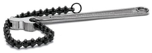
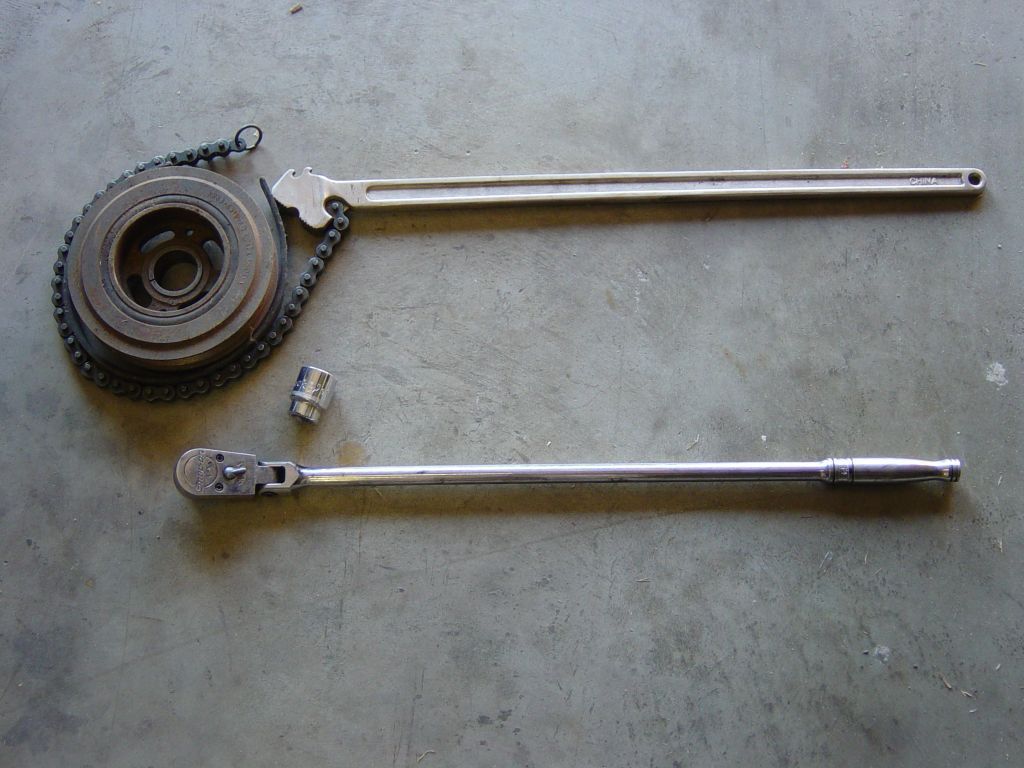
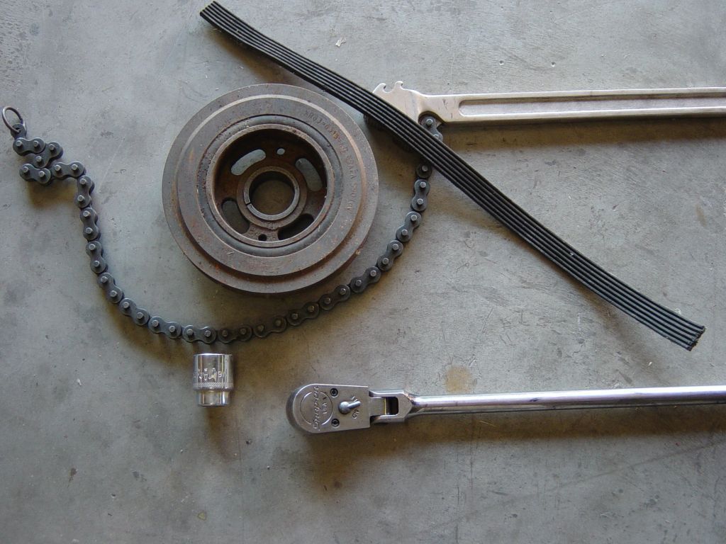
I found a spacer online for the harmonic balancer holding tool. I got the balancer off, which went fine after initially needing to use cheater pipes on the breaker bar and the holding tool.
But I have a new questionÖ.do I need to remove the thermostat housing and crossover pipe? It doesnít look like the timing cover is going to have enough room to come out from behind it. I havenít taken the bolts out the timing cover yet because if I have to remove coolant components itís going to be messy.
But I have a new questionÖ.do I need to remove the thermostat housing and crossover pipe? It doesnít look like the timing cover is going to have enough room to come out from behind it. I havenít taken the bolts out the timing cover yet because if I have to remove coolant components itís going to be messy.
#31
You will need to remove the aluminum crossover pipe and water pump also. Trust me on this. Also, when you get the front cover off, those 3 o rings on opposite side of the supercharger idler bracket on the inside of the timing cover must be put back in prior to reassembly. You can use rtv (or buy new ones) to hold them in place during reassembly. Donít forget to use a dollop of rtv on the front of the block (after itís been throughly clean and dried) where the bed plate meets the block, where the cylinder heads meet the block and where the top of the timing cover meets the top of the cylinder heads. These are seams that can leak oil if not properly sealed.
A word of warning if you replace the front main oil seal (which you should)... some of the new ones have a plastic (integrity??) ring on the inside. AFTER you install it onto the timing cover but BEFORE you install the cover on the block, remove this plastic ring and throw it away. I myself and I know others have as well installed the new front crank seal into the cover and installed it onto the engine without removing that plastic ring. The plastic ring can ONLY be removed from the backside of the seal which means once youíve installed it on the engine, you will either have to remove the timing cover again or destroy the newly installed seal and buy another one to install.
Replace the very thin o ring on the harmonic balancer where it meets the crankshaft.
The following users liked this post:
Don B (06-27-2022)
#32
You will need to remove the aluminum crossover pipe and water pump also. Trust me on this. Also, when you get the front cover off, those 3 o rings on opposite side of the supercharger idler bracket on the inside of the timing cover must be put back in prior to reassembly. You can use rtv (or buy new ones) to hold them in place during reassembly. Donít forget to use a dollop of rtv on the front of the block (after itís been throughly clean and dried) where the bed plate meets the block, where the cylinder heads meet the block and where the top of the timing cover meets the top of the cylinder heads. These are seams that can leak oil if not properly sealed.
A word of warning if you replace the front main oil seal (which you should)... some of the new ones have a plastic (integrity??) ring on the inside. AFTER you install it onto the timing cover but BEFORE you install the cover on the block, remove this plastic ring and throw it away. I myself and I know others have as well installed the new front crank seal into the cover and installed it onto the engine without removing that plastic ring. The plastic ring can ONLY be removed from the backside of the seal which means once youíve installed it on the engine, you will either have to remove the timing cover again or destroy the newly installed seal and buy another one to install.
Replace the very thin o ring on the harmonic balancer where it meets the crankshaft.
A word of warning if you replace the front main oil seal (which you should)... some of the new ones have a plastic (integrity??) ring on the inside. AFTER you install it onto the timing cover but BEFORE you install the cover on the block, remove this plastic ring and throw it away. I myself and I know others have as well installed the new front crank seal into the cover and installed it onto the engine without removing that plastic ring. The plastic ring can ONLY be removed from the backside of the seal which means once youíve installed it on the engine, you will either have to remove the timing cover again or destroy the newly installed seal and buy another one to install.
Replace the very thin o ring on the harmonic balancer where it meets the crankshaft.
New questions: I have installed the timing lockdown kit on the crank and cams. Iím ready to remove the sprockets, chains, guides, etc. The sprocket bolts seem tight. Can I just bear down and pop the bolts loose? Also, do I need to pay attention to the orientation of the sprockets relative to shafts? Or can I just pull everything off without marking it? Same question applies to all the guides and tensioners - can I just pull them all off or will I wish Iíd marked the orientation of everything?
I did take a bunch of pictures.
Thanks again everyone!
#33
The following users liked this post:
Don B (06-27-2022)
#34
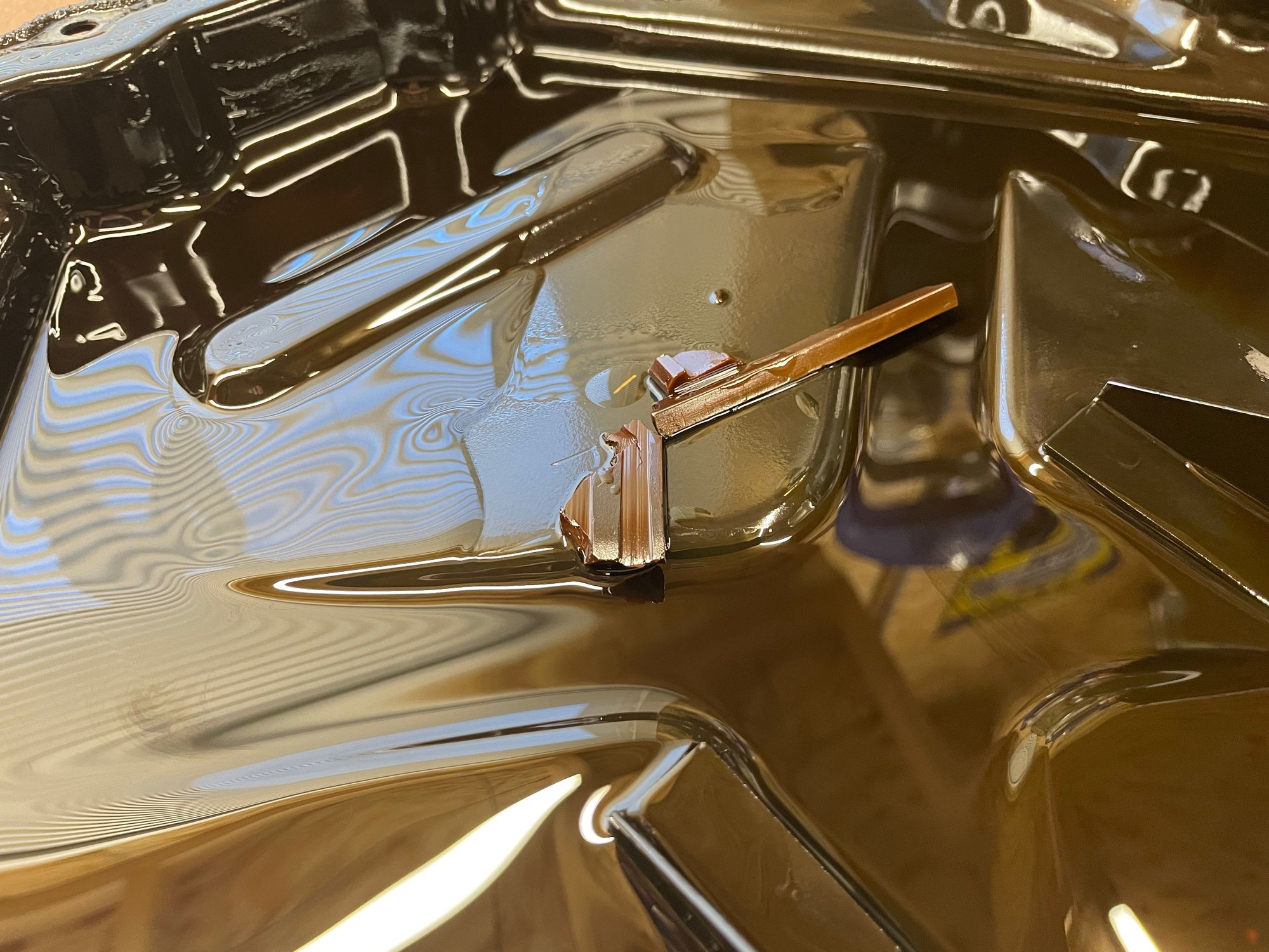
Two questions: The crank sprockets seem tight. Will I need a gear puller? And regarding the one tooth offsetÖwill that take care of itself when reinstalling the sprockets, because the keyways are offset, or do I need to know something more before I remove the old crank sprockets?
Take a look at the picture of my chain guides. Yikes!! Nothing left of them.
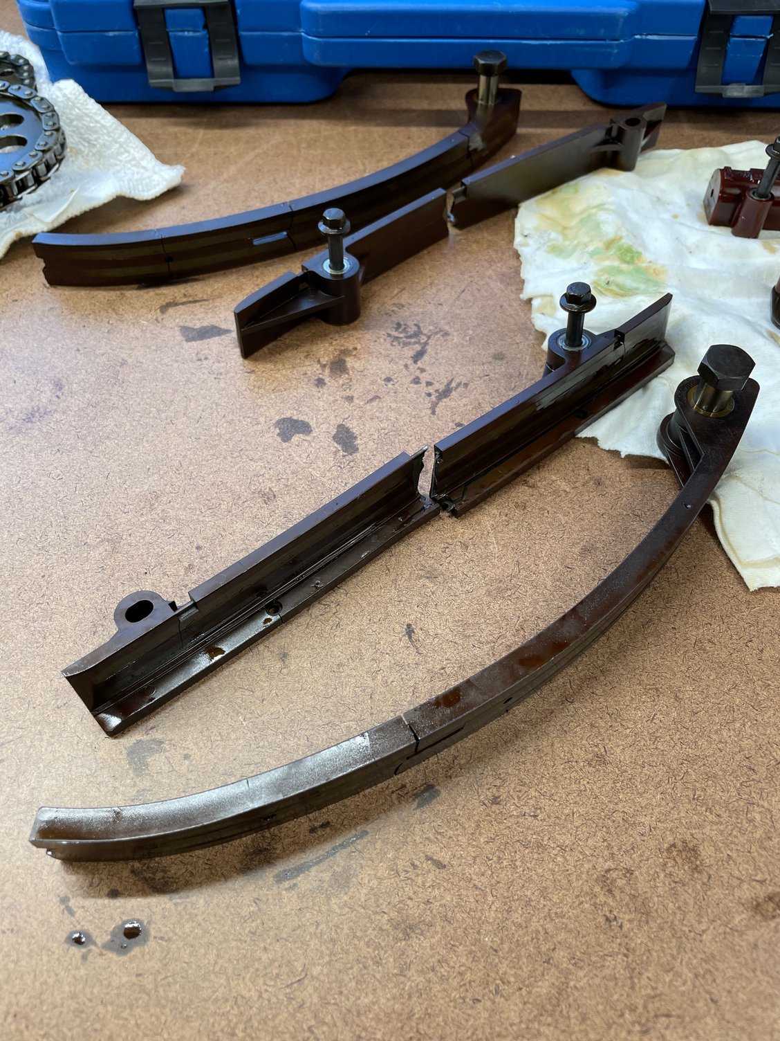
Last edited by aquifer; 02-13-2022 at 01:30 PM.
#35
I think I figured out the crank sprocket offset. After I slid them off I laid them out carefully and studied every millimeter of them, and I discovered that there are dimples on one side of each sprocket. When the dimples face each other, the one tooth offset is achieved. It doesnít seem to matter which sprocket goes on first, as long as the dimples are kissing. Does that sound right? If so, I think Iím good so far.
Last edited by aquifer; 02-13-2022 at 02:51 PM.
The following 2 users liked this post by aquifer:
Don B (06-27-2022),
motorcarman (02-13-2022)
#36
#37

I donít know about the offset, but I wonder if the normally aspirated sprockets are installed differently, so that the teeth are lined up. No idea why that might be, but otherwise youíd think they would just make one solid sprocket. There must be a reason that the sprockets are in two separate pieces, and turning them the other way makes the teeth line up.
Thanks for the advice. I think Iím on the right track. I need to clean the gasket surfaces, the cover, and all the parts, then install the new pieces. I will have more questions Iím sure. I donít want to make a mistake and have to pull everything back apart again!
#38
#39
Bob, I was thinking about the harmonics aspect end of it but, I just donít see that happening but, Iím not an engineer either. The only other thing I thought about is if the peened pins (ends specifically) on the rollers wouldíve been too close to touching the adjacent chain if the crank sprockets were inline vs off by a tooth??
#40


