When you click on links to various merchants on this site and make a purchase, this can result in this site earning a commission. Affiliate programs and affiliations include, but are not limited to, the eBay Partner Network.
In trying to setup a new throttle position sensor on my 1995.25 XJS 6.0, I found that the PDU was looking for the wrong values for the idle setting. The engine setup program didn't ID the ECU as being right for the vehicle, but if I clicked thru, it I'D the ECU with the right part number. What I didn't notice until after several aborted attempts, was that is was saying it was a 5.3 rather than a 6.0 V12. That makes no sense either from the model year/VIN or the ECU type. If I went into engine diagnosis, it identified everything correctly. Only in engine setup did it mis-ID. I'm using the last XJS CD. 626/7.
The workaround was to use VIN 194000, which was a 1994 model. I found they moved the vehicle setup menu under toolbox for 1994, where it was a separate menu for the 95.25. Under the 1994 VIN, it correctly ID'd the engine as a 6.0, and provided the correct TPS settings.
Anyone else ever run across this? I'm posting this as documentation should anyone else run across it.
I can and will help you but at the moment I am to busy with more important things in life so please be patient. I am unable to send you an pm as well, maybe you can let me know your email I can contact you directly.
I am wondering if you could put me on your list of people needing help with their PDUs? Mine won't even switch on...and my VBA cable is a mess as well (can be the problem here to be fair). The whole unit came with the car. I can't PM you as I am quite new here...I am interested in any way of getting mine to work...
I am wondering if you could put me on your list of people needing help with their PDUs? Mine won't even switch on...and my VBA cable is a mess as well (can be the problem here to be fair). The whole unit came with the car. I can't PM you as I am quite new here...I am interested in any way of getting mine to work...
Cheers, Mate
The typical issue with the VBA are the cables from the body of the VBA going to the banana plugs. Instead of a single wire, there are two to each plug, both positive and negative. One or the other wire in each cable breaks at the solder joint, then the VBA won't work correctly. Do a search in this thread, and you will find some pictures. In my case, both red wires were broken at the solder joint.
Look at posts #54 and #55 in this thread for more info.
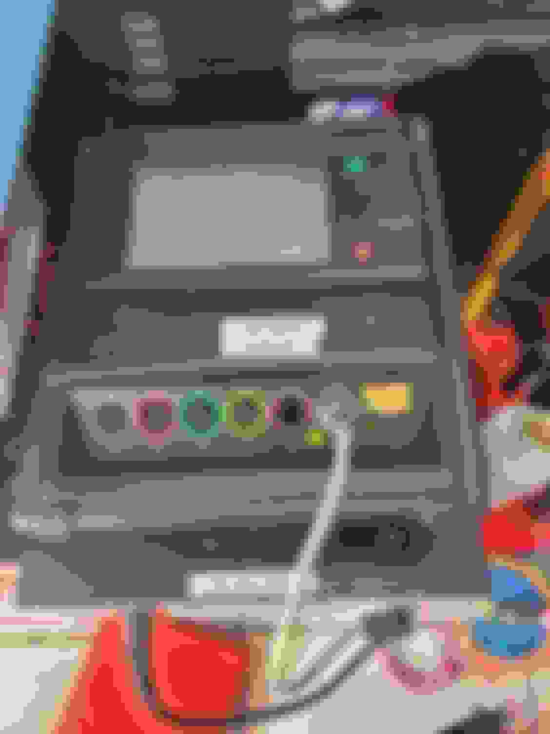
Ofcourse I will help, but first we need to know what parts do you have and do you get any response when you to power the PDU? You can power it with the VBA (and like jal1234 said, check the wiring inside the banana plugs even if it looks like the VBA is powered on an gives you a green light), or with the base station. Both ways you should see a battery light next to the grey plug on the PDU. Maybe your battery is dead, try to power the PDU with the battery disconnected and see what happens.
Ofcourse I will help, but first we need to know what parts do you have and do you get any response when you to power the PDU? You can power it with the VBA (and like jal1234 said, check the wiring inside the banana plugs even if it looks like the VBA is powered on an gives you a green light), or with the base station. Both ways you should see a battery light next to the grey plug on the PDU. Maybe your battery is dead, try to power the PDU with the battery disconnected and see what happens.
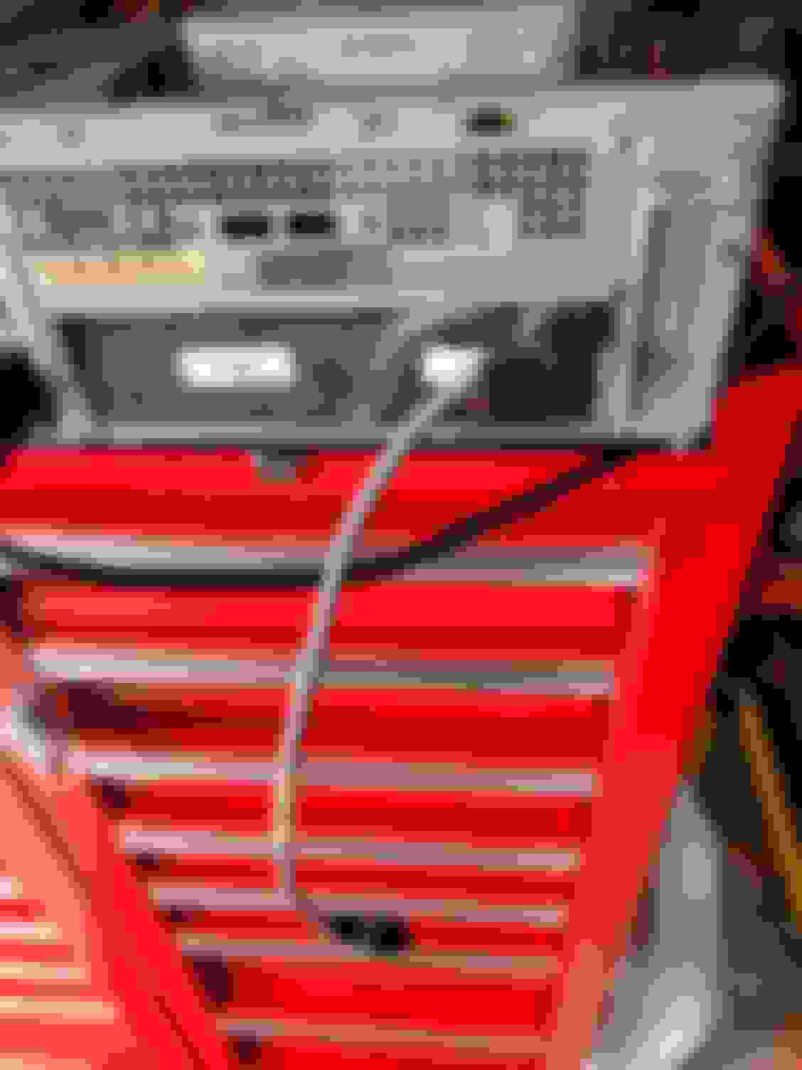
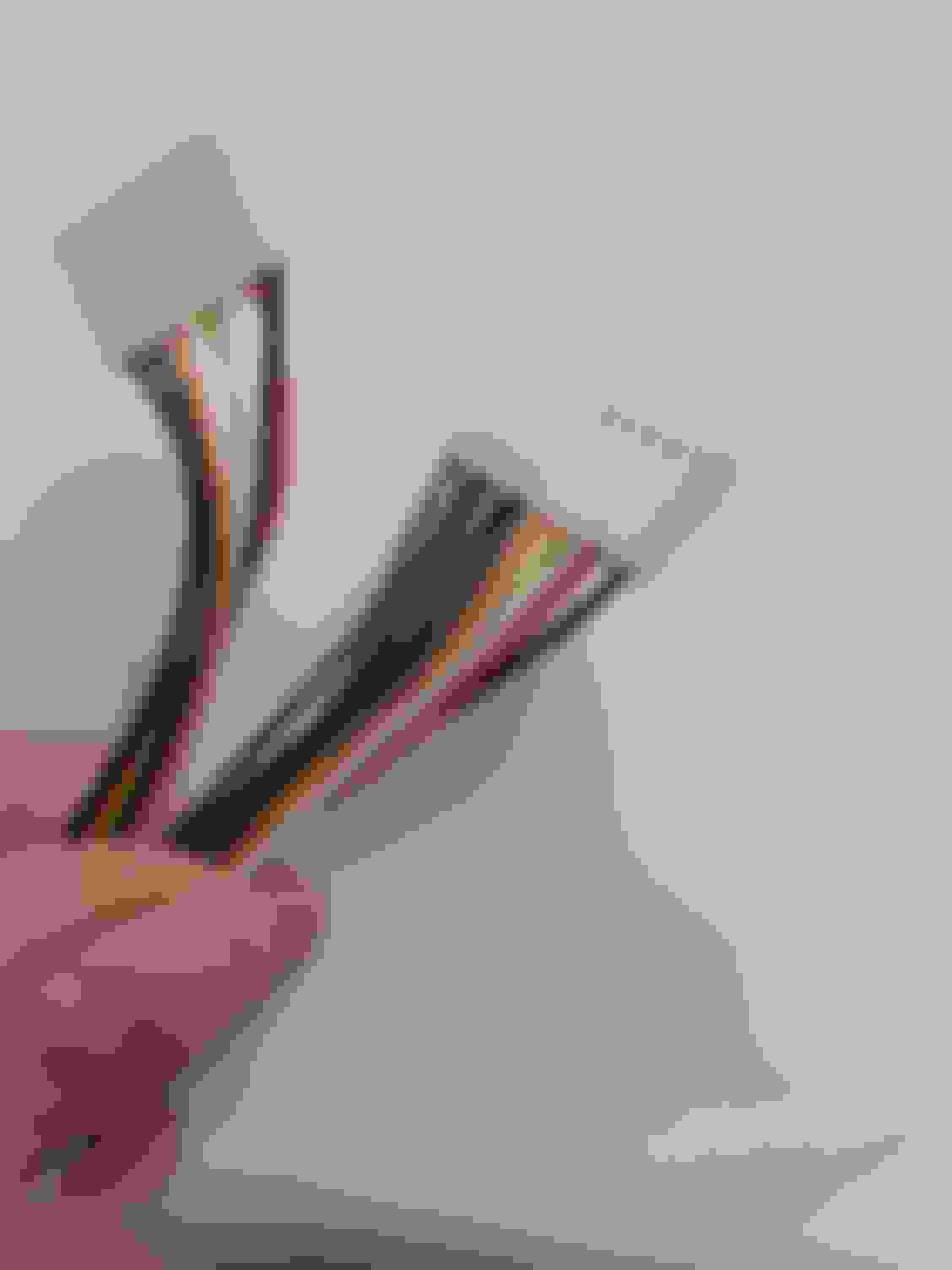
Thank you for a quick reply to you both! The VBA seems to be working, lights are coming on when connected to a battery. The plug to the PDU is broken, it was repaired in the past, but now it is completely shot...soldered and butchered...I have five wires in that connector, one positive, one negative and three seem to be non-responsive at all even when the VBA is hooked up to a battery. This can't be good. Of course no light is coming up next to the gray plug on the PDU.
What shall I measure in these wires when the VBA is powered with a battery? Even the layout seems to be a question now as the round terminal housing is broken too. Was there ever a wiring diagram available for this cable? Now I can mix up everything with each other...
Last edited by etypev12; 10-31-2022 at 03:21 PM.
Reason: typo
Was there ever a wiring diagram available for this cable?
Not that I am aware of . Personally I don't have the time to open the connector to see, but maybe somebody on here is willing to open their own and make you a pinout diagram?
If you connect the PDU to the base station, do you get a battery light on your PDU?
Not that I am aware of . Personally I don't have the time to open the connector to see, but maybe somebody on here is willing to open their own and make you a pinout diagram?
If you connect the PDU to the base station, do you get a battery light on your PDU?
Well...I only have a standalone PDU, a CD-ROM and the VBA main unit. I don't have the base station...am I completely gone without a base station?
I'm confused. How do you load your PDU without a base station? How do you hook up the CD-ROM?
A CD-ROM, a powersupply, an interface board and an interface cable is the base station.
Jon
Hi Jon,
The PDU and all its hardware came with the car (the DB7) in a basket all disconnected. I have never managed to turn it on...that's what I am trying now as the ABS light came on.
The CD-ROM...well I don't know how and where to connect it. The gray cable that is attached to it doesn't have a gray equivalent on the PDU...as that is occupied by the car diagnostic port connection already.
(If anyone has a full working set I am interested in buying it )
Matt
You disconnect the grey cable that goes to the car from the PDU, and connect the grey cable from the CD-ROM base station. Once you do that, and power up the base station, does the charge light on the PDU come on?
You have to use the CD in the base station CD-ROM drive to load the PDU with whatever test you want to do. You have to ensure that the proper CD is in the drive for whatever car you are working on. Once the PDU is loaded, you disconnect the grey cable from the base unit, carry the PDU to the car, and hook up the cables as shown on the PDU screen. Depending on what tests you need to do, you may need to run back and forth between the car and base station, reloading the PDU with the appropriate test.
The PDU is designed to stay in the base station charging whenever it is not being used. The battery only lasts a few minutes, just to get from the base station to the car.
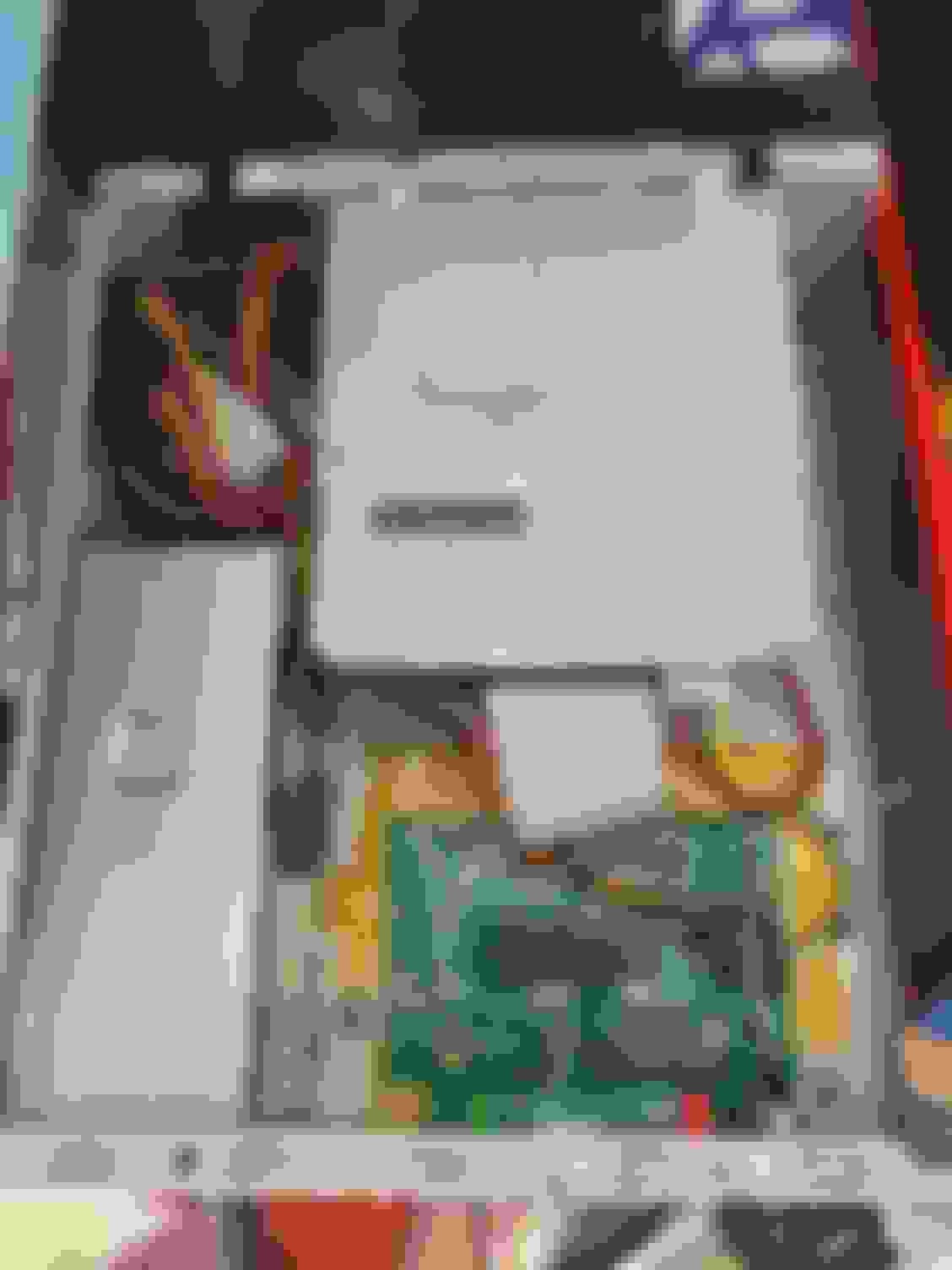
Take some pictures of what you have (PDU, base station/CD-ROM, cables, CDs, etc.) and post them here. There is some training literature on the system in the dropbox link in the first post of this thread that you should resd. Yes, the dropbox link is still active after all these years.
Just to make abundantly clear what the last post said�
Unplug the gray car wire and plug in the PDU base station grey wire to that port. You don�t attach the car to the PDU until the base station is running and has loaded software into the PDU.
The PDU and all its hardware came with the car (the DB7) in a basket all disconnected. I have never managed to turn it on...that's what I am trying now as the ABS light came on.
The CD-ROM...well I don't know how and where to connect it. The gray cable that is attached to it doesn't have a gray equivalent on the PDU...as that is occupied by the car diagnostic port connection already.
(If anyone has a full working set I am interested in buying it )
Matt
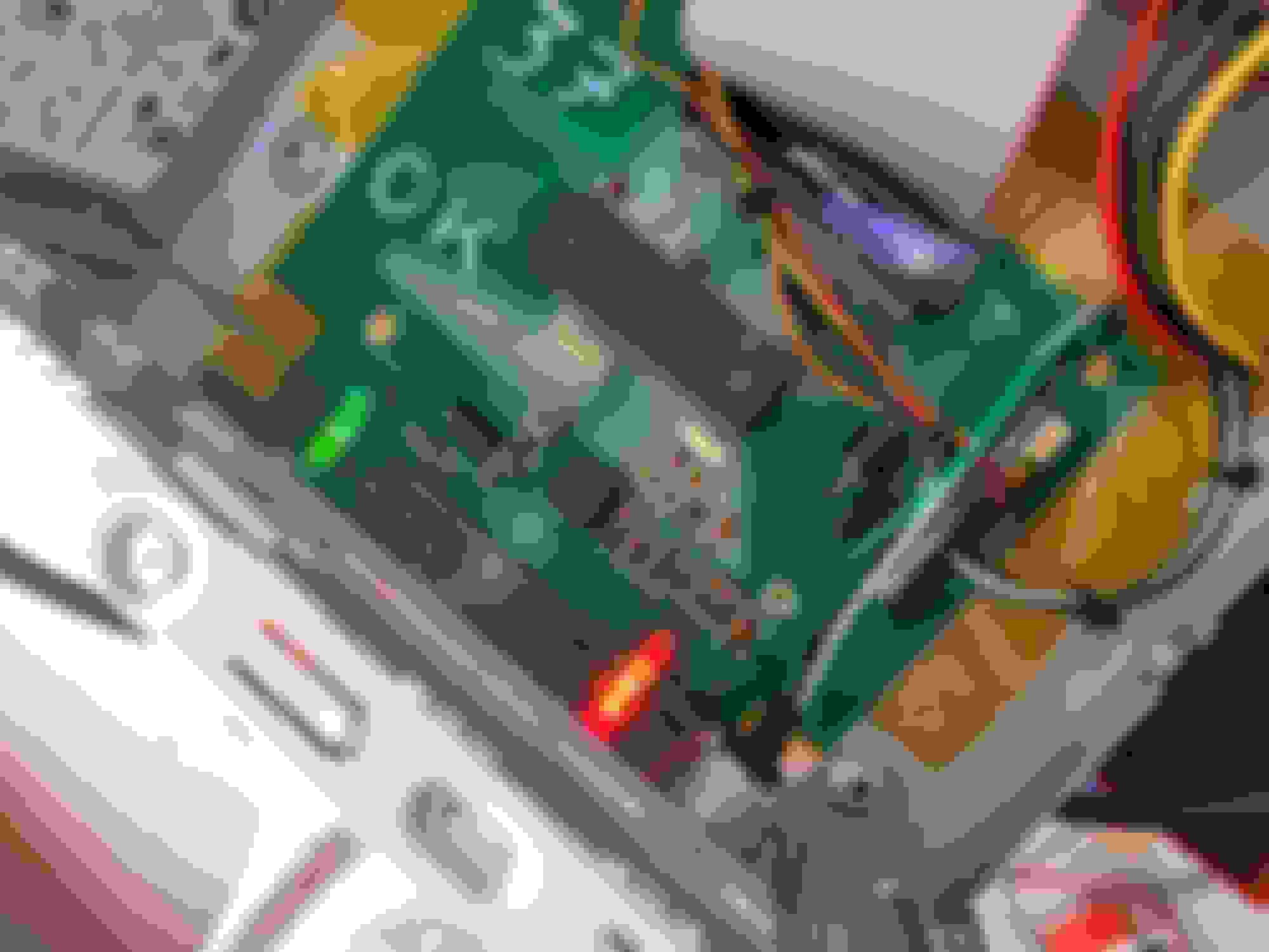
ok stop drop and roll�start taking pictures
do you have the AMPA and the cables to hook up to the zytek ecm?
Interested in pictures and what cables you have. I tried to get my hands on a pair of AM cables as they are different than the Jaguar cables. I am willing to try to copy the cables but I found out there is a programmable chip inside so I need to source a cable to try if it is able.
If you tell me if you have a non airbag (I6) or with airbag and the last 6 of your VIN, I can check for you what cables you need for your ABS light.
Even if you don't have the base station but the PDU and the correct cables you are fine as you can build a base station yourself.
If you have cable model 3130-1242-00 and willing to sell let me know.
I think besides the PDU you should be able to diagnose your ABS light with a WDS as well, in case you don't have the correct cables, software etc.
So, so many questions, as I am interested in the AM stuff. Where are you located? (Hungary?)
Edit: see you have a I6, non airbag if I am correct
Thank you for all the answers Gents
Yes, this is an early DB7 I6...so far every part for the suspension came for the Jag XJS was a perfect fit. Yes, I am based in Hungary.
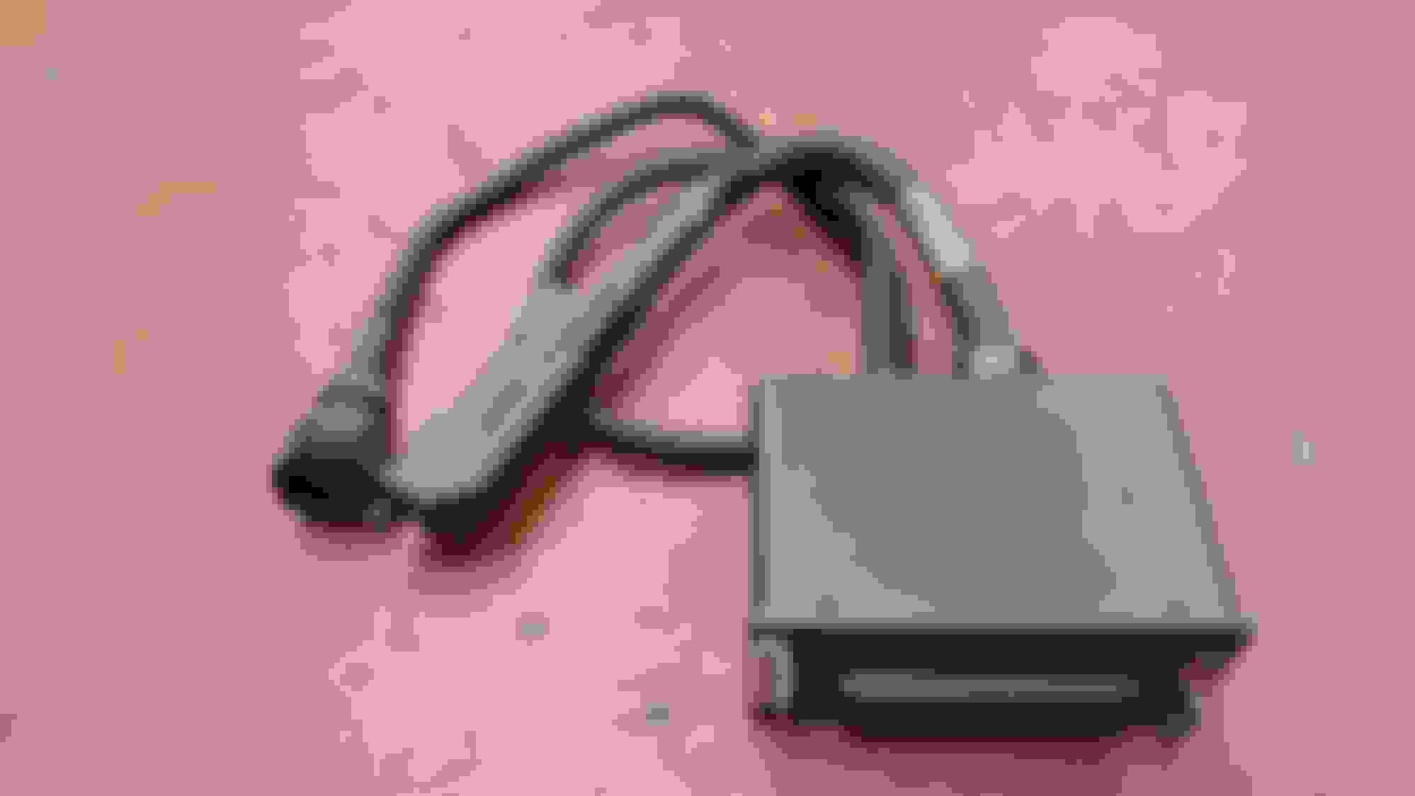
No, I don't have the base station, only an ancient CD-ROM drive with God almighty knows what CD in it. The AM plug and cable seems original, I will take a photo - if I remember correctly, that even has a part number decal attached.
Do I understand correctly, that without the base station I can't use a PDU? If the base station is the thing marked with yellow, than no...I don't have it.
I started up the PDU and your car has got the Teves MK2 ABS and it has got no fault memory and the only thing you can do when the PDU is connected to see live data. But I would start with a multimeter to check the resistance of the wheel sensors.
When trying to connect to your ABS system you need a lot of hardware including a brakeout box for the Teves ECU.
How to wire the PDU up for ABS with all the cable numbers Teves brakeout box
If you would have a MY97 than you would need the 16 pin obd cable interface:
So for your ABS problem I don't think the PDU is very helpful but it is always nice to get a PDU back working again.
With Gijzzy's help, I successfully built a PDU base station using one of his CD-ROM interface boards, an old, small, computer case and power supply, and parts ordered from various suppliers. You will need: 1. Gijzzy's interface board. PM him directly to order. It took about 2 weeks to get to the US from the Neatherlands 2. A compatible IDE CD-ROM drive. He uses a Toshiba SD-616 drive to test the boards before shipment. I HIGHLY recommend buying one of them. A lot of IDE CD drives will NOT work, especially with burned CDs from images in the first post in this thread, even though they read perfectly fine on the same drive in Windows. Any drive you get is likely to be used anyway as no one makes new IDE drives. I bought mine off ebay. 3. A case to put everything in. I used an old computer case i had on hand, along with its power supply. 4. A computer power supply. 5. A Lumberg KGV40 connector for the PDU interface cable. A Lumberg KFR40 will also work. I bought mine from Newark in the US. 6. Connectors for the interface board. I used some connectors I already had, but I later found the correct connectors on Ebay. You'll need a 7 and 10 pin connector. https://www.ebay.com/itm/33382646316...mis&media=COPY 7. Something to mount the interface board inside whatever chassis you use. I insulated under the board with Kapton tape, then used double side foam tape to mount the board. 8. Heat shrink tubing to insulate connections at the interface connector. You might also need some hookup wire.
Gijzzy's board and connector pinouts are in the "ATAPIPinout-2.pdf" attached below. You only need to connect pins 4-6 and 10-13 on the white strip connector as indicated in bold. The pins are numbered on the board from the bottom of the picture to the top.
Pins 10-13 are connected to the power and ground leads of the computer power supply. On the output wires of the power supply, Black is always ground, Red is always +5volts, Yellow is always +12v. Gijzzy's pinout shows +14v in and out. I used another 12v input for this from the power supply and have had no issues. Use some of the harddrive/CD-Rom output cables from the power supply for the voltage inputs to the circuit board.
Pin 4 of the board goes to pin 1 of the connector as shown in the pdf. Pin 5 goes to pi 4 of the output, pin 6 goes to pin 3, and you can use any of the black pins on the board to hook to pin 2 of the output connector. Double check all of your wire routing. Do NOT pay attention to whatever colors you end up with on your board connectors. Follow the pin to pin numbering diagrams. Nothing connects to the 2 pin header at the top left of the interface board, or the header in the middle of the board. Only the white strip connectors are used.
Most computer power supplies will turn on if you short between the Green pin on the large mainboard connector on the power supply and any Black pin on the same connector. A photo is below. I didn't bother switching the power supply as the PDU is meant to be plugged into the base station charging when not in use.
The CD-ROM drive can only be connected to the output ribbon cable of the interface board in one way, as it is keyed. The Master/Slave/Cable select jumper next to the IDE connector MUST be set to Master. You can use any of the other yellow/red/black power cables from the computer power supply to provide power to the CD-ROM drive.
Lumberg connector photos:
Shorting between green and black pins of computer power supply connector to power on:
Ebay interface board connectors:
Part 2 will deal with building the connecting cord between the base station and the PDU.
How to DIY build a PDU base station, part: the cable.
Now I'll deal with the PDU to base station connecting cable.
DISCLAIMER: I have not built this cable as I got one with my PDU. However, I reverse engineered my cable, and am reasonably certain this is correct, both by measurement, and taking off the backshell of the connector.
You will need:
1. Neutrik OSC8F Neutricon connector kit. It cyontains everything you need for the PDU end of the cable, except for the grey backshell. I got this from Mouser in the US.
2. Neutricon BSP-8 grey backshell. Got this from Mouser.
3. About a foot of 4 conductor cable
4. 220 Ohm 1/4 watt resistor. This can be obtained from any electronic parts house. Try to get a high accuracy resistor, as the one in my cable is a 5 band color code (red/red/black/black/gold). Mine measured almost exactly 220 ohms.
5. Fine gauge hook up wire. You have to jumper a few pins in the PDU side connector.
6. Lumberg WSV 40 connector for the base station end of the cable. I got this from Newark.com in the US.https://www.newark.com/lumberg/wsv-4...t=lumberg%2040 This is a right angle connector. It is not exactly the same as the original, but it will work. If you want a straight connector, get SV 40-8, also from Newark.
Soldering is required. You will need a fine tip iron. The OSC8F connector will also have to be assembled.
Pin to pin layout is in the diagram below. The resistor goes between pins 3 and 7 of the Neutricon connector. Pins 5&8 and pins 2&6 also have jumpers between them. I forgot the jumper between 5&8 below. The Lumberg connector end just has straight connections to the cable. Neutricon OSC8F connector kit Grey backshells Original cable part number Original cable
Good luck!
Jon

 10-15-2022, 02:11 PM


 Mine won't even switch on...and my VBA cable is a mess as well (can be the problem here to be fair). The whole unit came with the car. I can't PM you as I am quite new here...I am interested in any way of getting mine to work...

 )
)