When you click on links to various merchants on this site and make a purchase, this can result in this site earning a commission. Affiliate programs and affiliations include, but are not limited to, the eBay Partner Network.
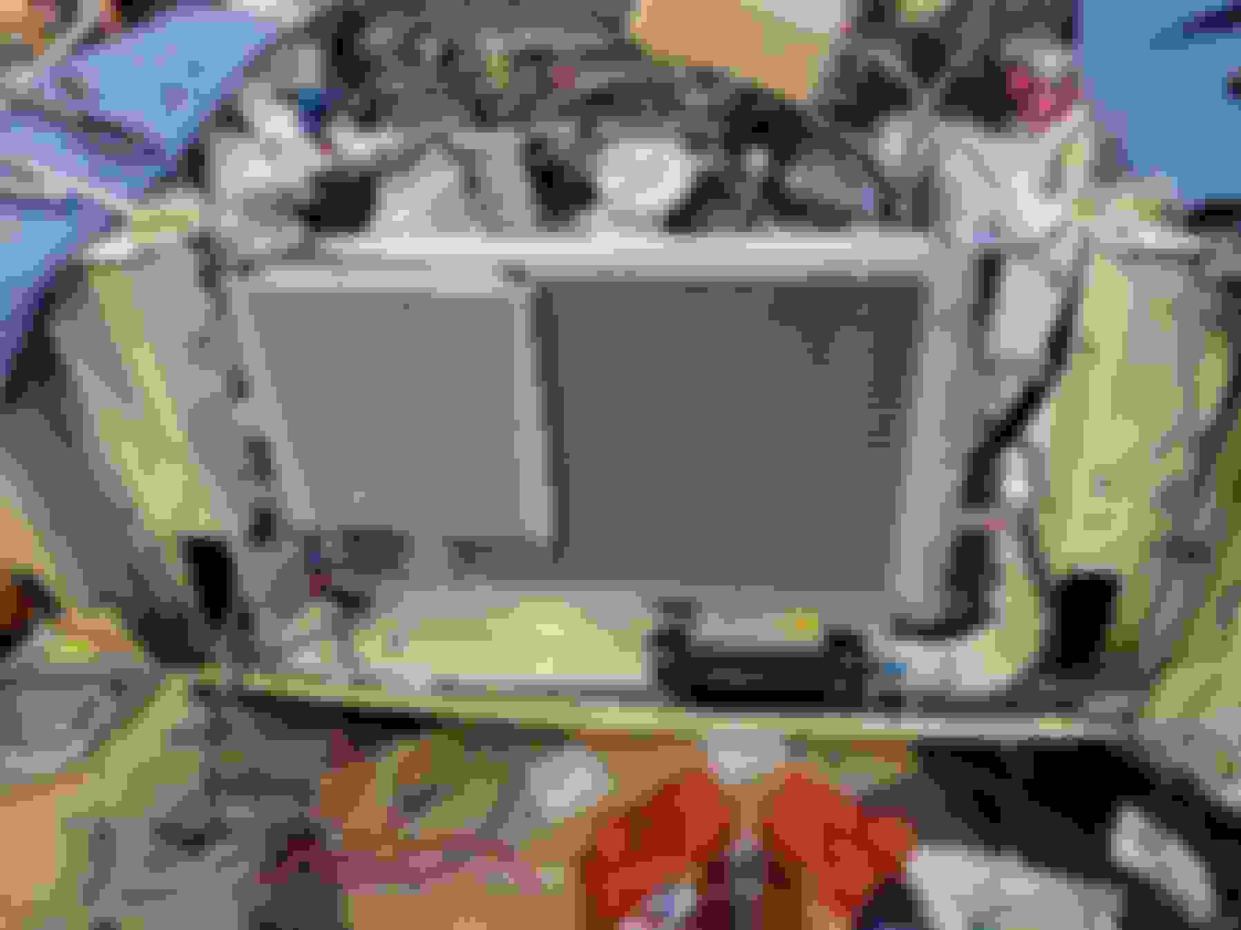
Even though I had both of my heaters going full blast, I was only about to get 45 minutes of work in before it just got too cold. First up was revisiting my radiator mount. I mounted a 2' long piece of 3.5" x 1.75" to the bottom of the radiator opening. This will put my radiator at the correct height.
The radiator perfectly straddles the piece of aluminum and puts the top of the radiator at the correct elevation to use the factory top mount. I think this is a better way to handle chassis flex.
At this point I decided the fun/cold ratio was tilted too far to the freezing side and I closed up shop. We're supposed to hit the 40's next week so I'll be able to get more done then.
I have just the opposite temperature problem with today's thermometer reaching 38C which is 100F and the humidity is around 70%.
Sweat won't dry off and glasses continuously fogged.
Had to retreat from the shed and sit under some fans.
I'll just have to leave the Jags in peace.
The weather in Chicago is above freezing and I was able to get back out to the garage today. I started out by working on the top mount of the radiator.
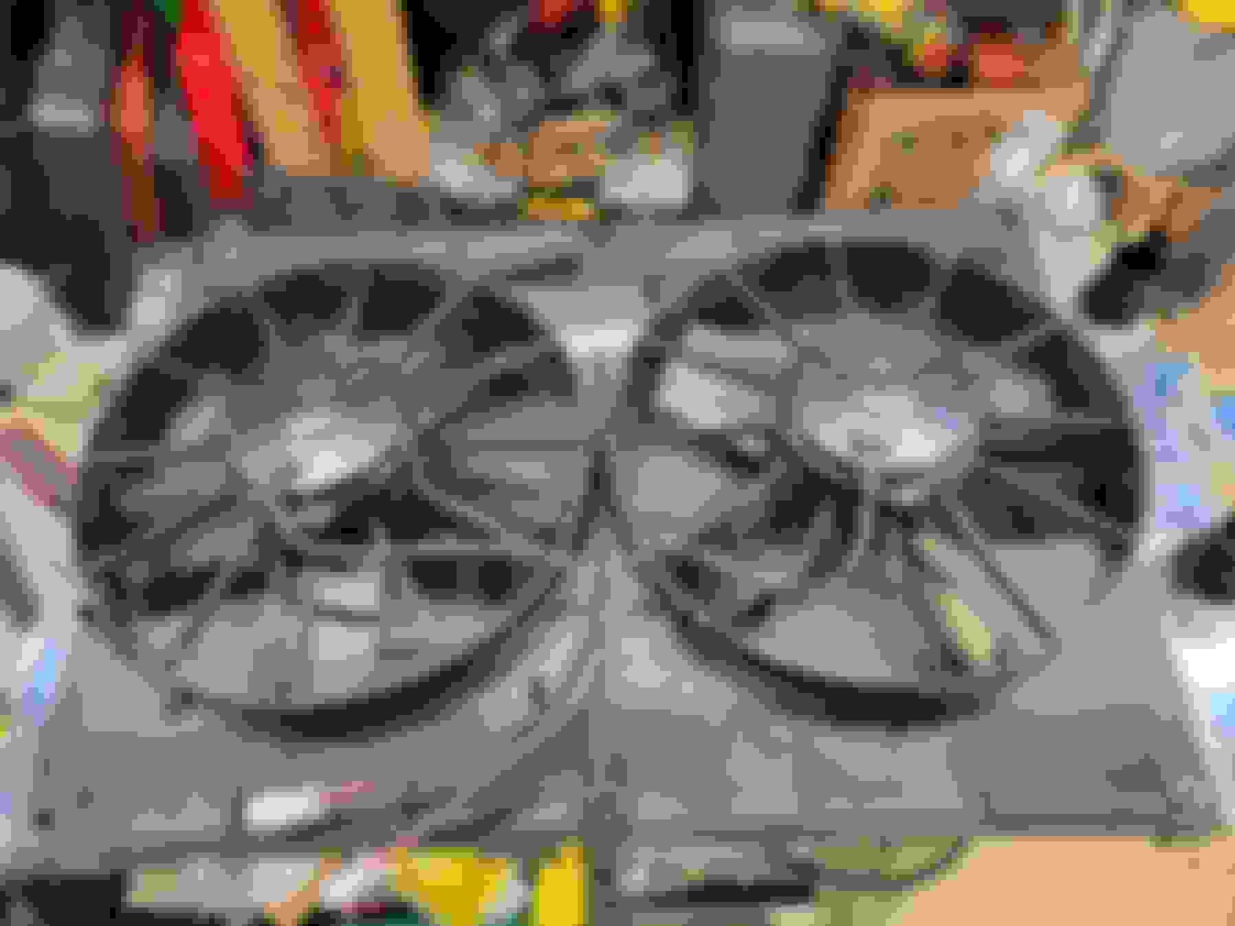
I also decided the 1,000 CFM of the Ford radiator fan wasn't attractive to me so I picked up a dual 11" Spal fan set that is rated for 2,720 CFM.
It comes with rubber flaps that open up at speed and close when the fans are on. I expect this will be more than adequate to keep things cool.
My goal is to have all the plumbing done by the end of the month so today I made the last fuel hose from the filter to the engine.
The other end attached to the filter.
I also finished up the heater hoses and radiator hoses.
The lower radiator hose has a 1/8 NPT fitting so I can install the temp sensor for my PWM fan controller.
The Gates PowerGrip hose clamps really clean up the appearance,
I also replaced the brake master cylinder with one from a S3 XJ6. I have another thread about it but it's cheaper to buy a S3 master cylinder than it is to buy a S2 brake fluid reservoir.
I also started plumbing up the AC system. The Vintage Air U-Bend-Em aluminum lines are easy to work with.
Here is the suction line from the evaporator to the compressor. I've collected so many fittings over the last 20 years that I had most of what I needed already on the shelf.
As much as I really didn't want to put this bumper back on, it was time to reinstall it before the final install of the radiator.
I'll have to save up my nickels for the kit to put on the S1 front bumpers.
Wonderful quality work as always!
I have had a little experience with those inline fittings for the NPT sensor in the bottom hose. I feel it is important to support the hose at that point somehow, rather than just have it loose in the air, otherwise they have a nasty habit of gradually coming off the hose.
Cheers
Lots more activity today. I re-shimmed the power steering pump to drop the outlet pressure from about 1.300psi to around 850psi. My wife also made a guest appearance in the garage to help bleed the brakes.
After that I was able to get the fans mounted and tested. These things move a ton of air.
I put the hose ends on the lines for the transmission cooler and got that all hooked up.
I also made the high pressure line from the output of the parallel flow condenser to the receiver/drier.
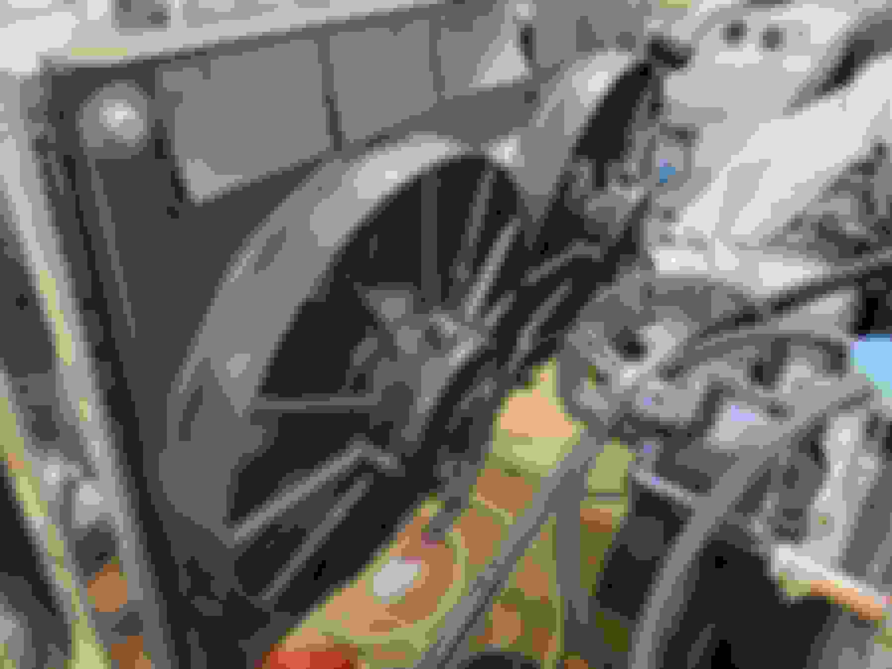
After that I started making the baffle plates for the sides of the radiator to make sure air goes through the radiator and not around it.
Another idea on the fans is series and parallel wiring through two relays. Both run in series for low speed and both run in parallel for high speed. Use the ign switch for low speed, temp/ac sensor for high speed. I run my corvette like this and it works great. Also GM and Ford did this in some years.
I had the house to myself tonight so I brought the engine wiring harness in and stretched it out over the kitchen counter. I tagged all the connectors when I pulled the harness off the engine but I still needed to identify which connectors hooked up to the car. A quick look on eBay and I was able to find the matching 5 harness connectors I need to wire the engine PCM to the car. This means I don't have to hack the engine wiring harness to get things to run which is always a huge plus.
Yezzzz...
Husband also gets a little testy also when I bring car parts into (Shudder, Gasp) Food Preparation Areas!!
What is it with spouses??!
It's nothing that won't clean up, for heaven sake!!
Tonight I finished documenting the feeds I need into and out of the engine wiring harness. I feel like I have a fairly good understanding of how I want to pull all this together without making a rats nest of wires under the hood or behind the dash.
I also got my fan controller in the mail today. I need to find a good place to mount it.
The front brake calipers I rebuilt a few months back would not stop leaking, even after I took them apart and rebuilt them a second time. I believe the new pistons I bought were not up to spec and were not sealing. A rebuilt set of calipers seem to fit the bill and I spent the morning installing and bleeding the brakes again.
From there it was on to the wiring. I started with mounting my fan controller on the left side inner fender, well away from the exhaust manifold. I also started wiring the fans to the controller.
It looks like I might have enough slack in the engine wire harness to mount the PCM in the passenger footwell. I need to get under there and make sure there is enough room to mount it.
I thought it might be a good time to wire up the new gauges, so I made sure my wife wasn't looking and I brought the dashboard inside to work on it.
Wiring up the power, ground, and illumination wires was relatively easy. The last set of Speedhut gauges I bought came with a dimmer but this set did not - I need to see if I can get one.
And lastly here is the startup sequence for the gauges. Aside from the voltage gauge none of them are hooked up to their senders so there's nothing to see.
...The last set of Speedhut gauges I bought came with a dimmer but this set did not - I need to see if I can get one....
I found the dimmer to be pretty useless from Day One as I always had it "wide open," so last time I was in there I wired across it. Dash lights are Much brighter now with straight through power.
(';')
Can they be set to whatever the PPM is on a given car?
It's even easier than that. You select a calibration speed, put the speedometer to calibration mode, then drive the calibration speed and let the speedo figure out how many PPM's your car has.
I went with the GPS speedo because it's even easier but I am starting to wish I had gone the programmable speedo route.
I found the dimmer to be pretty useless from Day One as I always had it "wide open," so last time I was in there I wired across it. Dash lights are Much brighter now with straight through power.
(';')
Thanks for the tip. I just looked at what the dimmer options are for their new LED gauges and I think I'm going to skip it.
Most of today was spent deciding where I wanted to put the PCM. I thought the passenger footwell would be a great place for it and lined it up.
The PCM all nestled in the passenger footwell.
While I initially thought this would be a great place for it, loosing 3-4" of passenger legroom was a strike against this location. The final strike was when I realized how big the firewall pass-through would have to be to get the connectors through. So I decided to mount it in the engine compartment where the battery used to be.
With that decision made, next up was removing wires from the harness that I would not need. The 25 year old harness tape put up a fight but I was able to get the harness down to the individual strands.
I still need to pass a bundle of wires from inside the car to the engine compartment and thought I would try this grommet. It's machined aluminum and is in two piece so it should protect the wires and look professional when I am done.
With all the decision milestones made it's time to start wiring. There's no rushing this part of the job.
I had a crummy day at work so I cooked dinner for my wife and went out to the garage for a while. My new accelerator cable came in today so I lined it up to see how well it work. I was lucky that the pedal end was the correct shape and it slipped right in.
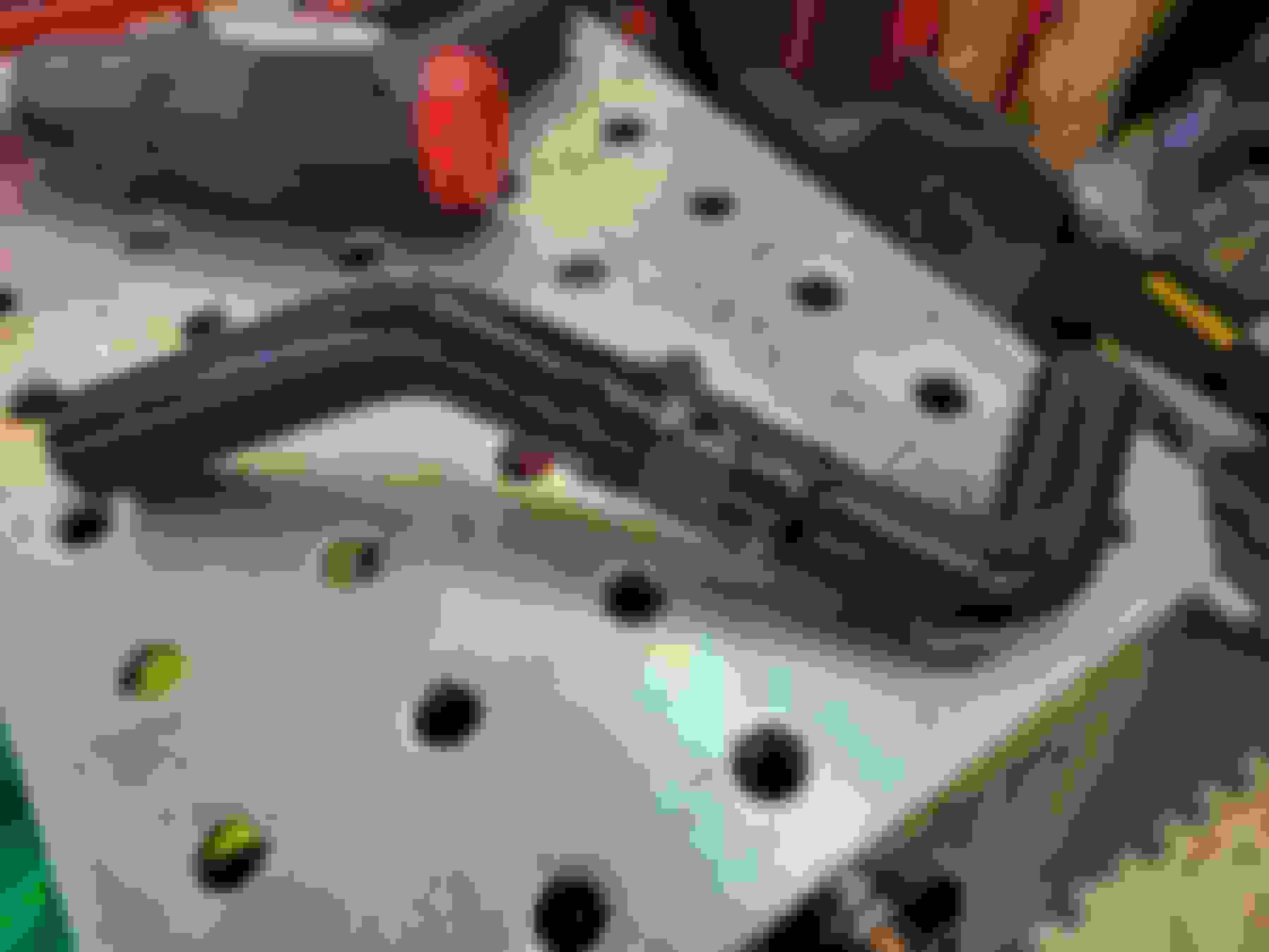
As part of the engine conversion I need more key-on circuits than the stock fuse box could handle. Since I replaced the entire AC unit I pulled the driver side HVAC fan, sealed off the opening with a piece of plastic, and moved the stock fuse box up. Underneath that I installed a 6 bay fuse box. Since it needed to be hot with the key on, I wired a 120 amp relay to a key on circuit and fed it 12 volts from an existing key on circuit. 120 amps is overkill for this circuit but I always say overkill is the best kind of kill.
In the above picture you can see the insulation is damaged on the wires going to the brake light switch. The recirculating air flap on the air box was playing pac-man with these wires. I'll replace them while I am here.
I really lucked out when I bought my engine, came with everything, including the under hood fuse panel, which was as simple as running a hot from the positive bulkhead bolt to it, and only one small connector had to go inside car, are you using shbox and lt1 swap to get your wiring information?
That's probably the way to go but no one has ever accused me of being smart
I started with LT1Swap, found SHBox, then realized my 1996 engine/transmission were sufficiently different from the diagrams on there that I bought the 10" stack of factory manuals and have used them for the wiring. SHBox in particular was invaluable for things like radiator and heater hose wiring and LT1Swap was helpful for removing wires I don't need.
On your car do you have EGR hooked up? It seems most people don't but I have seen a few installs that do.
 01-20-2024, 10:34 AM