When you click on links to various merchants on this site and make a purchase, this can result in this site earning a commission. Affiliate programs and affiliations include, but are not limited to, the eBay Partner Network.
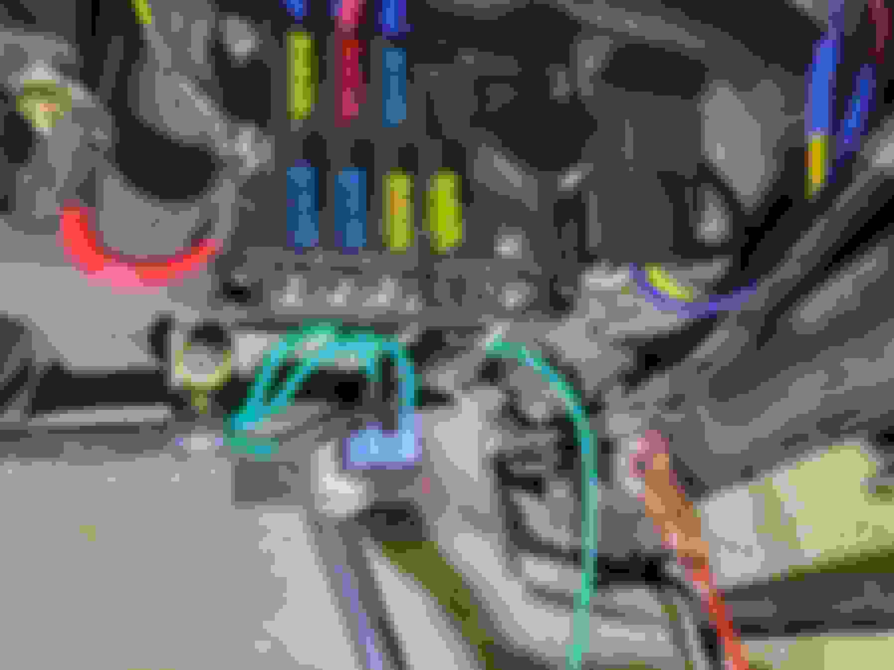
...In the above picture you can see the insulation is damaged on the wires going to the brake light switch. The recirculating air flap on the air box was playing pac-man with these wires. I'll replace them while I am here.
YES!!
This is one of the more Interesting design features of the Series 2! I found the exact same problem with mine, so I moved the wires and tied them up so they Never are in that position ever again.
(';')
Egr is not hooked up one mine and I am running the blanking plate on the intake, it does have to be deleted in the tune too if that�s how you go, I used moehorsepower for my tune, initially sent him the pcm, but subsequent tunes were emailed to me as I got the needed hardware and software to edit and install new tunes! When I say subsequent tunes I don�t mean that the one he did was bad, I just needed tweaks made, like idle speed and ac controls,
I spent the weekend out of town but got back in the garage this evening. I started wiring two circuits from the new fuse box to the engine bay but stopped when I ran out of pink wire. It's not a fashion statement; I'm using the same wiring colors to make it easier to troubleshoot later if I need to.
I happened to catch a glimpse of a brake fluid leak from underneath the front left caliper. If you're keeping track, I rebuilt the original calipers and they both leaked from the pistons. I replaced the bore seals and both sides still leaked from the pistons. I spent some time with the dial calipers and decided I either had some out-of-spec caliper pistons or some bad bore seals. So I bought a remanufactured pair of front calipers and now the front left is leaking. It's either the caliper half seals or the brake line going into the caliper. I cleaned it up and will check it in the morning. I almost hope it's the hard line going into the caliper because that's an easier fix.
Then I noticed the PDWA switch had fluid leaking up through the wire terminals. I said some bad words because the braking system has been giving me fits and there is no reason for it. After looking at my options I think I am going to go with a 16x1.0 MM bolt to plug the PDWA switch port. I did that on my MGB 30 years ago and it's still working fine (except that was a different size bolt).
Tonight I was determined to find the leak in my front left brake caliper and succeeded. One of the seals in the remanufactured caliper was leaking. I'm debating if I try my luck with another rebuild caliper or if I just bite the bullet and buy two brand new ones from Moss and call it a day. But I'm not ready to decide yet.
Then I moved on to the wiring and started knocking circuits off one by one. I got one more fused circuit ran out to the engine compartment and I started working on some of the interior circuits like the tachometer feed and the Park/Neutral position switch.
Every circuit is checked twice and then when I am confident it is correct I put a check mark on my worksheet.
My plan for the weekend is to make a substantial dent in the circuits that need to be wired. We'll see how it goes.
Thorsen
Is that black box with Rhapsody on it a main power up relay that comes on with the ignition?
I consider it more of the secondary power up relay specific to the engine. It powers things like the injectors, the heated oxygen sensors, the transmission, etc. It's rated for 120 amps and I'm planning on pulling half that through it so I'm expecting it to have a long life. The main power up relay for the car remains unchanged.
It was a cold day in Chicago but I turned on both heaters and got to work. I decided I would start with the wires that go to the brake light switch - it looks like the fresh air flap had been chomping on these since the day it left the factory. Lots of corrosion on the wire.
New wires and they got routed out of the way of any dangers. You can see an extra wire heading off the right edge of the screen because...
The PCM needs an "open when brake depressed" switch and I have the opposite of that.
So I added a relay to the right of the fuse box so I have a circuit that's normally closed, but opens when brake is pressed. The PCM needs that to unlock the torque converter.
I still have an extra brake wire but that's for the cruise control that's coming later.
I wired up a handful of other circuits and ended up at the ALDL connector/OBD II port. While it's not necessary to include this it makes trouble shooting much easier.
After double-checking all the connections I hooked up the battery, plugged in my code scanner, and crossed my fingers. I don't have any sensors plugged in but I was able to connect to the PCM and see readings which tells me that I'm on the right path with my wiring.
My goal tomorrow is getting the radiator fans wired up.
I started today with putting on another remanufactured front left brake caliper and have been crossing my fingers all day that this one does not leak. So far so good.
I then moved on to wiring the fan controller. I've learned to use quick-disconnect fittings on these as welding on the car with the controller connected will fry it. I started with a short run of wires from the controller to the connector.
Most of the way done. I like using Deutsch connectors as they are durable, sealed against the elements, and easy to assemble.
The S2 XJ has a non-locking headlight dipper which requires a latching relay to hold the high beams on when they are activated. The popular VW latching relay is expensive and very fragile - I think I got a week out of the first one I bought before it fell apart. It uses a mechanical latch that didn't always work.
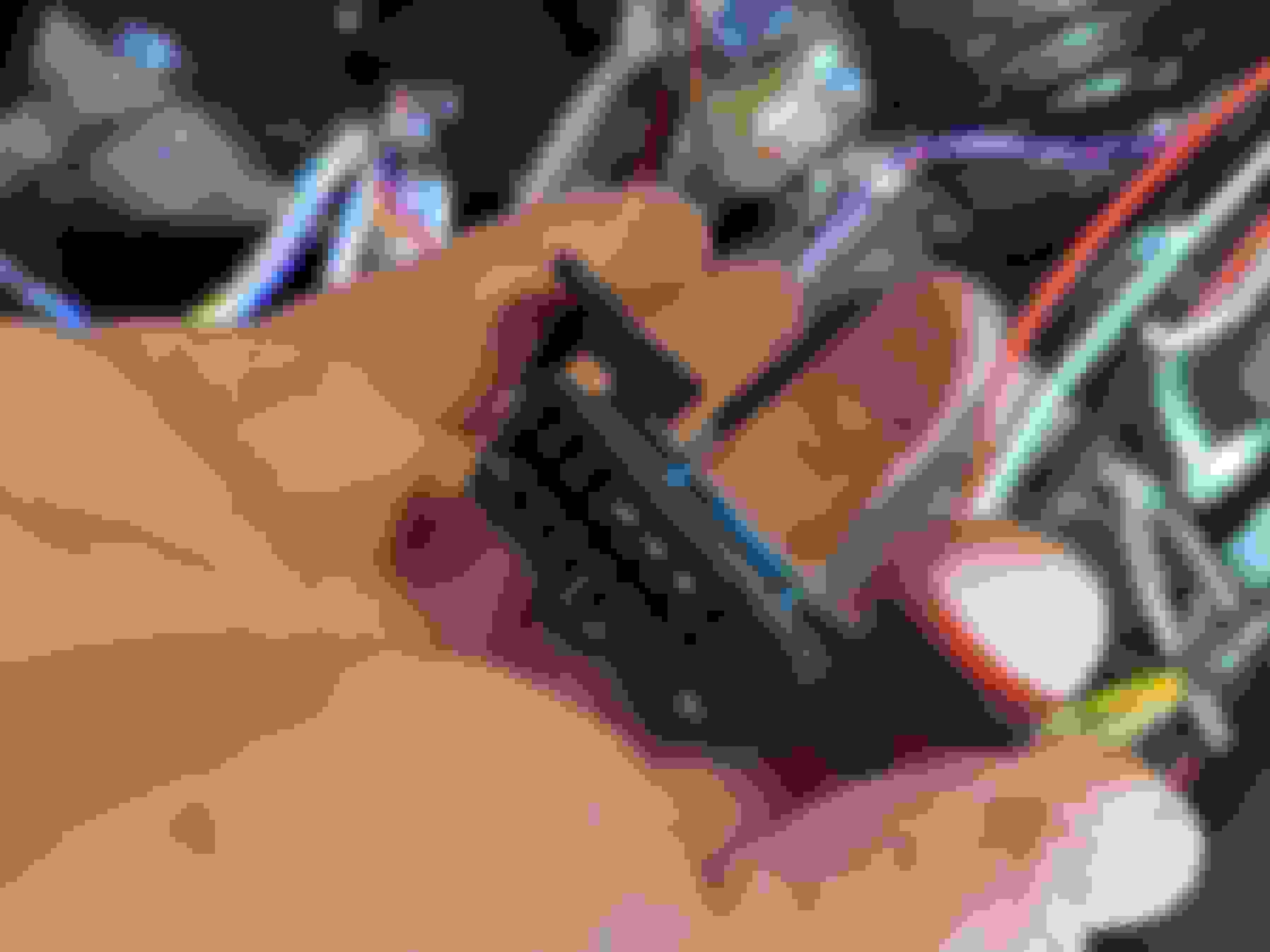
I was looking for a better way and came across these latching relays. The two screw connectors on the right power up the relay. The three connectors on the left are the normally open, common, and normally closed connections. The wires coming out of the bottom are the trigger - touch them together to latch and unlatch the relay.
I sat down and came up with a diagram using the latching relay and separate relays for the low and high beams.
I found a combo fuse and relay box which seemed like a good base to start building.
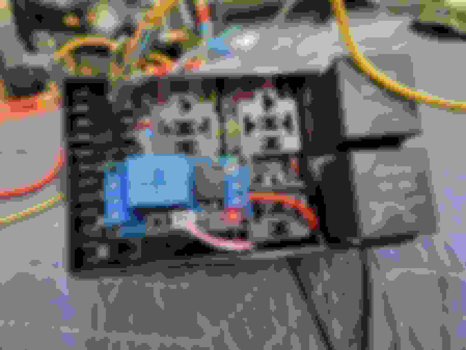
Testing out the relay mid-build. The red light shows the relay is powered up and the normally closed (low beams) output is active.
I flicked the high beam stalk and now the green light is light. The relay has clicked over and now the low beams are off and the high beams are on. Pulling the stalk again turns off the high beams and turns on the low beams.
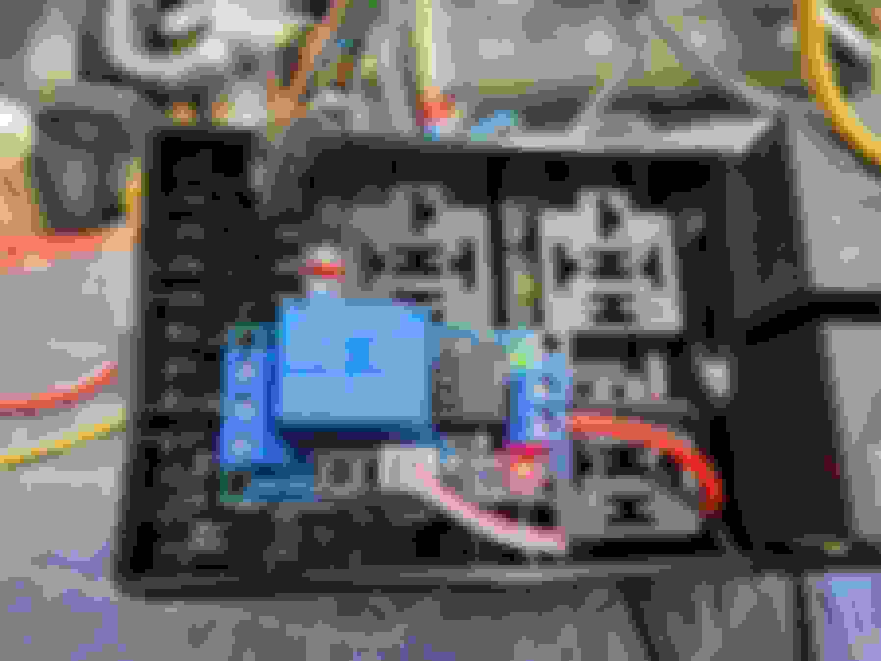
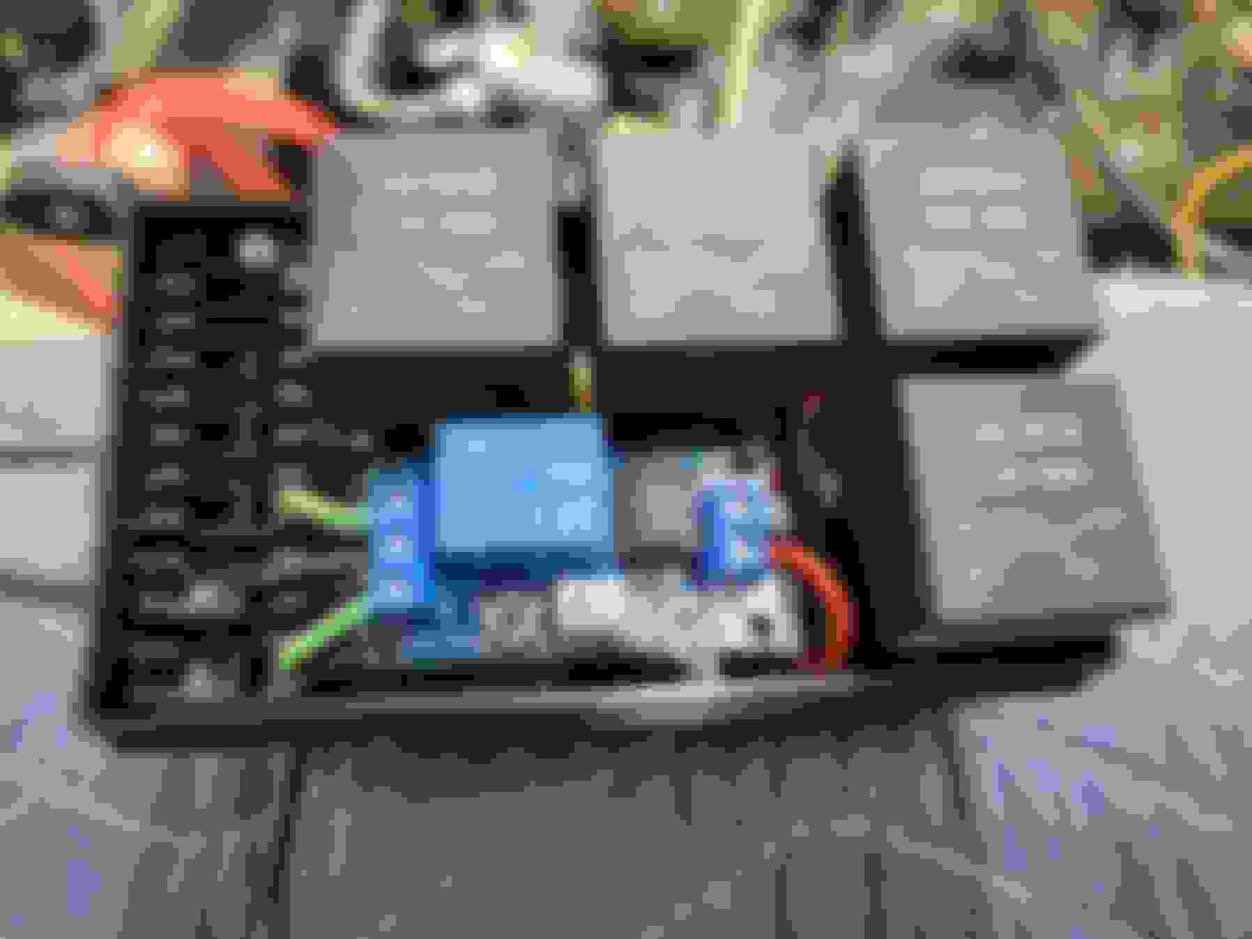
The top row is the low beam relay, high beam relay, and the power-on relay.
The bottom row is the latching relay and the high-low relay that controls the latching relay. I still need to add the fuses.
The plan is to have all the wiring finished this month and the goal for today was getting the cruise control wired up. I started with connecting the cruise cable to the throttle.
Once I was happy with the throttle attachment I looked for the best place to mount the cruise unit and decided the front section of the left inner fender would be a good place. I've been using the Dakota Digital units for a while now and am very happy with them.
To make things easier I went with the magnet kit on the driveshaft to provide the cruise control brain with a PPM signal.
The zip tie nearest to you is there to make sure the magnets are all in the same plane. I like to glue them and zip tie to the drive shaft.
I made a simple bracket to hold the pickup coil.
The rest of the wiring for the cruise was very easy to do.
I also decided on the layout of my air filter today. I started laying out the engine wiring harness but ran out of wire loom.
The biggest wiring obstacle that is left are the fuel pumps. I set the center dash back in place so I could decide how I wanted to handle that. In the end I decided the best way was for the fuel pump relay wire from the ECU to go through the impact switch then to tank selector switch. In the trunk I'll run the left/right wires from the switch through relays for the pumps and also to control the valve for fuel return.
Last thing on the agenda today was to decide how to handle the recirculate/fresh air flap and the defroster ducts. I retained the factory setup for those including the vacuum motors. I found these air switches last year when I needed something to control the scuttle vent on my 420 and they work great. The switch can direct engine vacuum to the motor or atmosphere which has the effect of opening or closing the motor. The flow restrictors on the right side of the picture are adjustable and keep the flaps from slamming into the full open or closed position. I need to find a place to mount them then plumb them up.
Another eventful day in the garage. I picked up about where I left off yesterday - after thinking about it last night I decided the air filter should be supported so all that weight wasn't hanging off the rubber couplers. The air intake came with the beginnings of a support but I needed an angle to finish it off.
I decided to mount the air valves on the driver's see under-dash scuttle. While it's not as convenient a location as the dash, I also didn't want to drill a hole in the dash for these. I think for as often as I'll need to use the defroster and/or switch to recirculated air this will work fine.
I also added a small momentary on push-button switch. I'm going to wire this into the fuel pump relay circuit to provide a priming feature.
You can see I also started plumbing the vacuum source for the switches.
After that, it was time to move to the back of the car. It was 55F/33C in Chicago today so I was able to open the garage door for a little extra room. The first order of business was running the hard fuel lines to the bulkhead fittings I put in last year sometime.
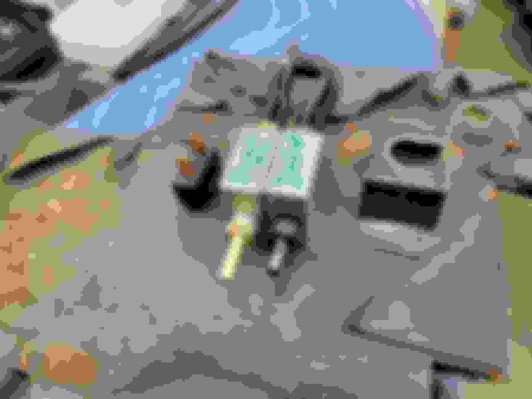
My original plan to use a surge tank ran out of steam when I realized there really were no good places to put it. So I reverted back to twin high pressure pumps with a Pollak valve to direct the fuel return to the correct tank. But first I needed a bracket to mount the Pollak valve.
Pollak valve in place. There are really on two wires I need: +12 volts on one and negative on the other and one side of the valve is open while the other side is closed. Reverse the polarity and the valves changes position to close the open side and open the closed side. I will just be using the small ports on the bottom for the fuel return to the tank.
I could have used a single fuel pump drawing through the Pollak valve but decided not to.
Here's a 20 year old picture that I dusted off today. A while back I had a Saab 900 that I wanted to add keyless entry. The keyless entry kit I bought came with two wires - one was +12 volts to lock and the other was +12 volts to unlock. The lock controller in my Saab had two wires that needed +12 and ground to lock and reverse to unlock. I called up my Dad the Civil Engineer and explained what I wanted to do - he came up with the below schematic to use the keyless entry. It worked perfectly.
Why are we talking about Saabs? I'm in a similar position with my Jaguar. I have two wires in the trunk: one has +12 volts when the left tank is selected and the other has +12 volts when the right tank is selected. The Pollak valve needs +12 and ground, or ground and +12 volts to switch the valve. I'm going to build something similar to get the Pollak valve the right voltages based on which tank is selected. Except this time I think I can use the 87a terminal to cut the number of relays I need in half.
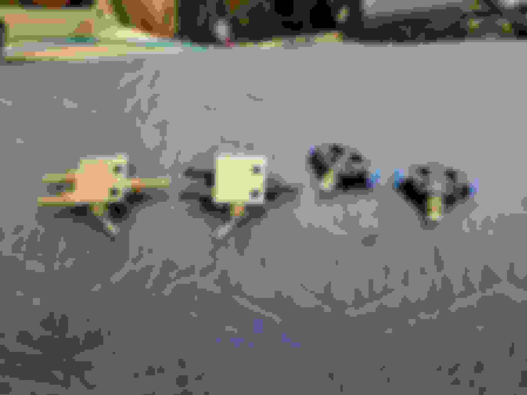
Tonight I worked on plumbing the high-pressure side of the fuel system. I'm using a fuel pump for each tank and rather than plumb it through the Pollak valve, I decided to run the output of each pump through a check valve and into a tee that goes to the engine compartment. If the left pump is running, the right tank check valve will prevent fuel from entering that half of the system. I mounted the check valves to the rear edge of the trunk.
I am two hoses and a handful of hose clamps away from completing the plumbing of the fuel system. In the picture below you can see the left tank pump, both check valves, and the tee. I will be able to leak-test the system this weekend if all goes well.
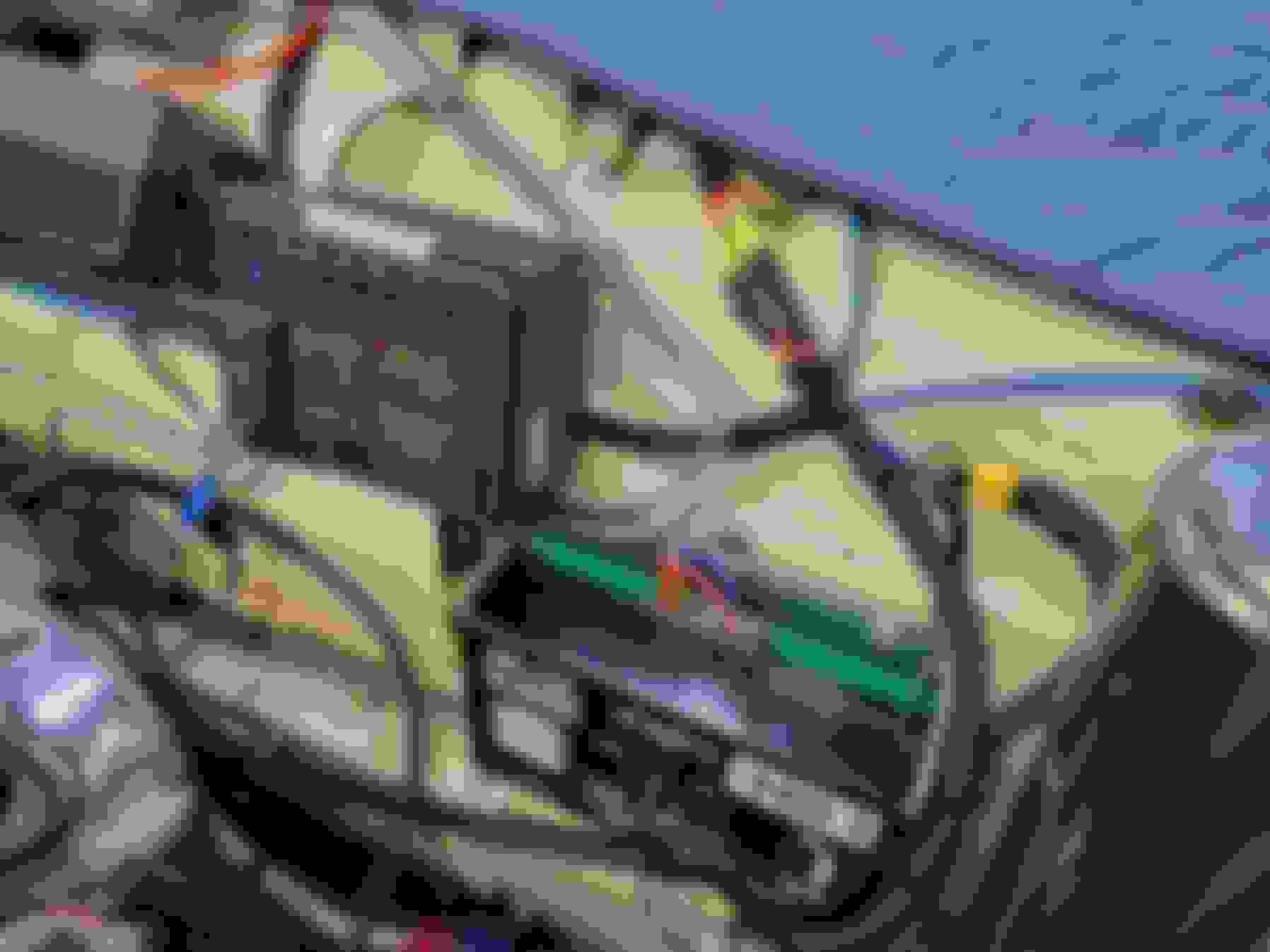
After that I worked on re-looming the engine wiring harness. The corrugated plastic loom was old and brittle and looked out of place. I used braided black harness wrap and Tesa high-temp harness tape to finish it off.
Extremely elegant and inherently reliable fuel system in the boot, Thorsen. Will you manage the changeover using the OEM cabin switch?
As these high pressure pumps last about 20 seconds if they run dry, have you thought about maybe using a warning buzzer or some such as the tank being used empties, or is there a warning light OEM you could hook one up to?
Greg,
I'll be using the factory change-over switch. It will make things slightly more difficult in wiring the Pollak valve but it's one less switch I would need to add somewhere.
You bring up a good point about a low fuel level warning. When I bought my new gauges Speedhut does give you the option of a gauge with a warning light. I have them on my MGB and they work well but when it came to the Jaguar, I decided I don't like the 0 point of the scale being at the 6:00 position. If you get the warning light you're forced into the 6:00 0 point.
Also, the tachometers and speedometers all have the 0 point at 7:30 so you get a situation where some of your gauges have 0 point at 6:00 and others have them at 7:30. It's a minor thing but it really irritates me.
I'm also the kind of person who fills up before 1/4 tank so it's a moot issue for me.
I agree about the dials; the needles all resting at different places would drive me mad too!
i still think that with high pressure fuel pumps you are tempting fate without a buzzer in each tanks, as in famous last words! It is not that you would run out of fuel; only that you would forget to switch and thus human error do you in...
Cheers
 02-06-2024, 10:47 AM