When you click on links to various merchants on this site and make a purchase, this can result in this site earning a commission. Affiliate programs and affiliations include, but are not limited to, the eBay Partner Network.
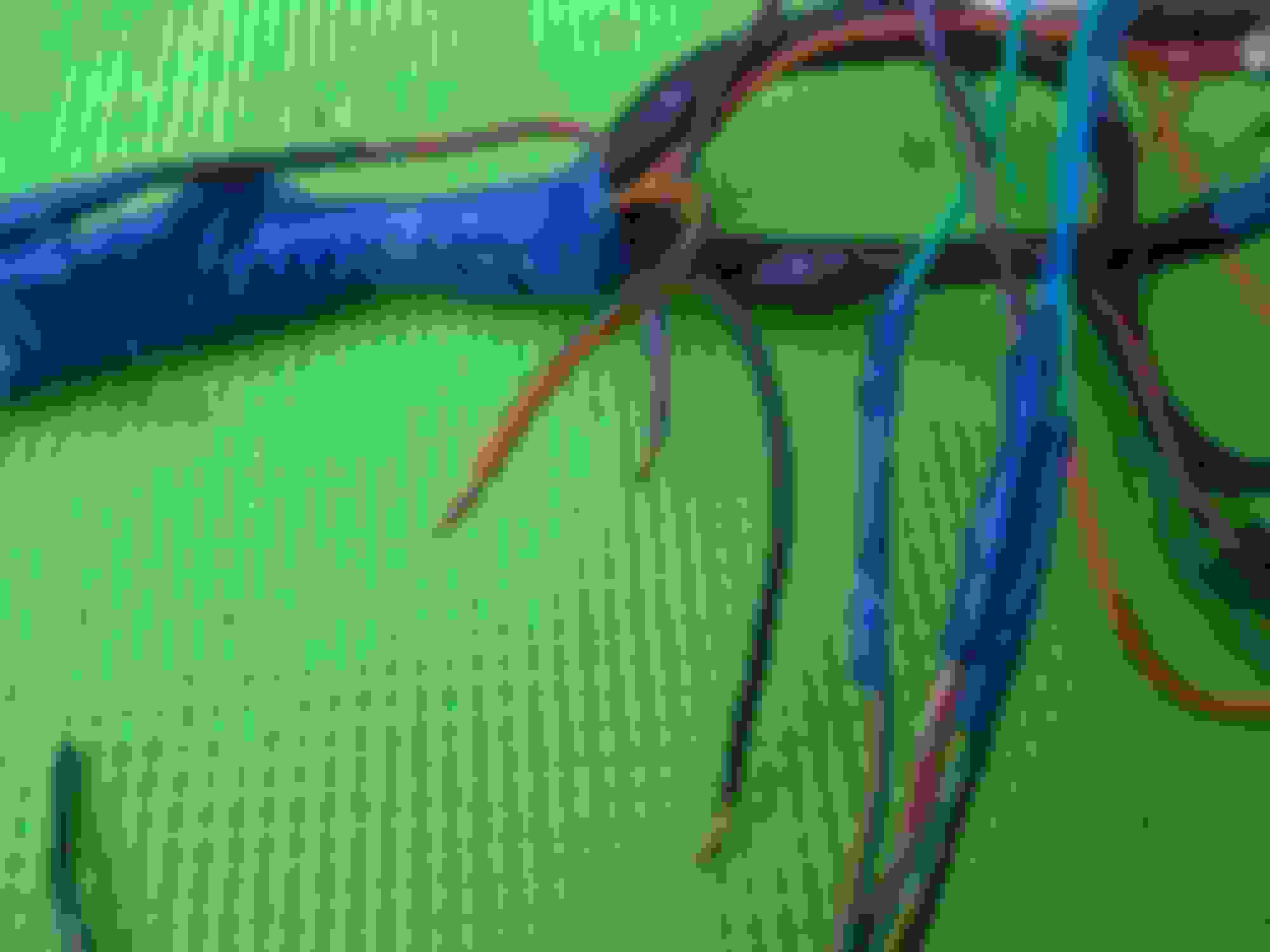
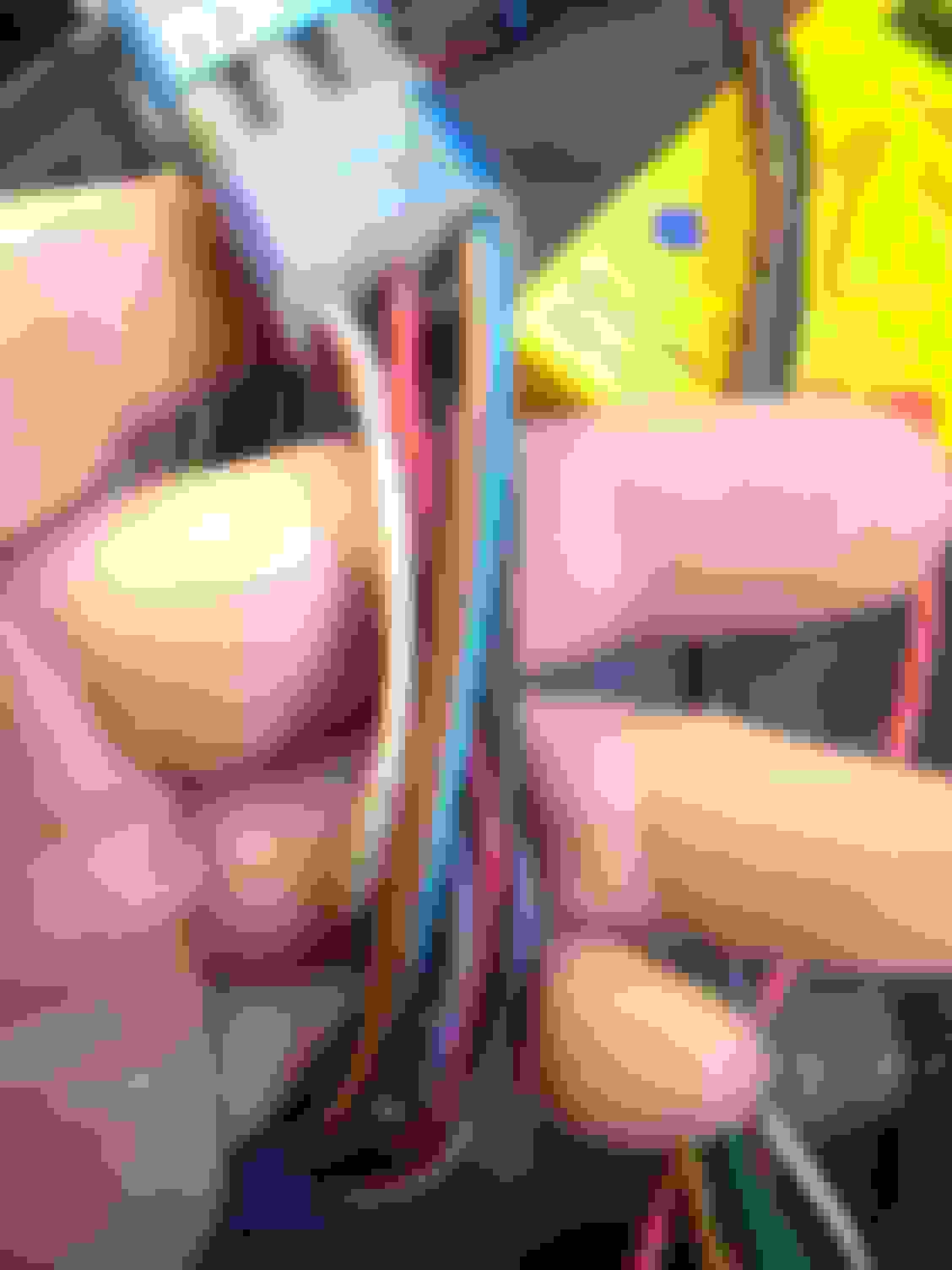
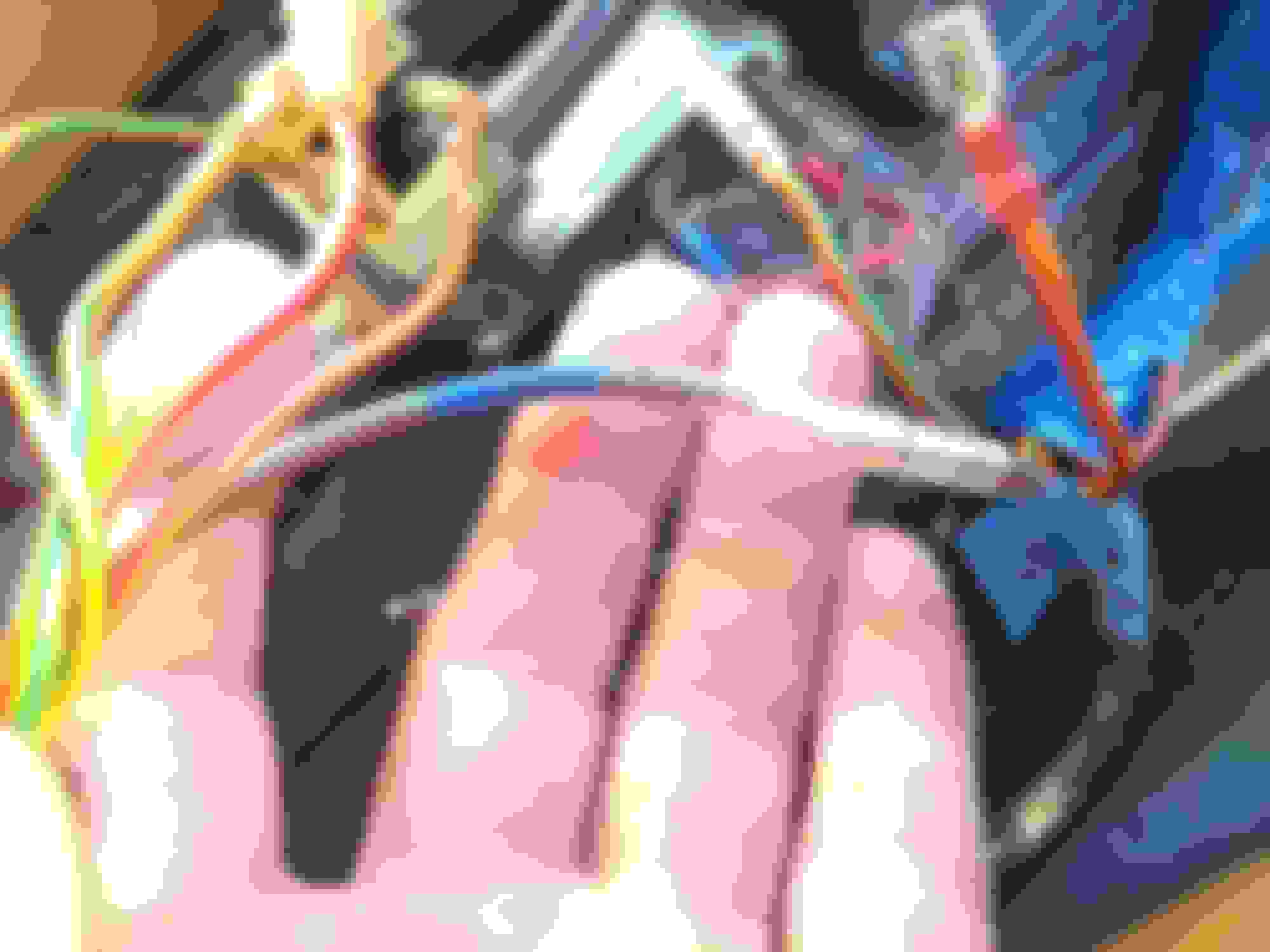
Pulled out the wire bundle under the console (that's very Dr Who...) and it's in pretty good order there were a few loose ends that must have been cuts by various owners over time and that I can't now figure out entirely. From one of the plugs a purple cable travels to a dead end for example. A loose black earth cable and a loose orange/green cable appear at a juncture too.
More confusing is the red with grey twirl/spire tracer. It has three loose ends poking from one juncture, two of which appear to run continuity between each other and the third connects back to one of the wires plugged into the relay behind the gear shift stick. Now what does this relays do if wires from it end in 'dead space' so to speak...?
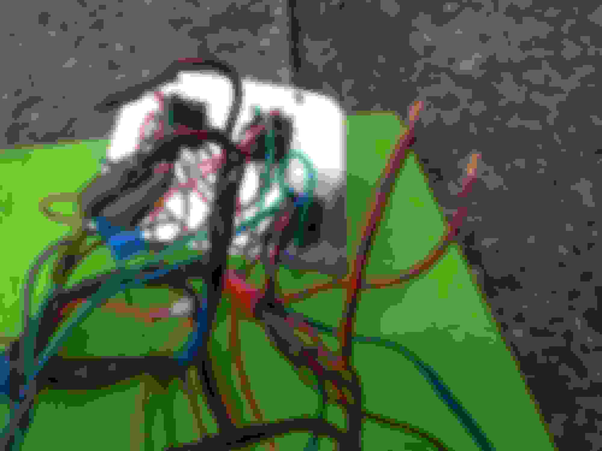
some of the rogue wires the wire bundle and window slope behind the gear lever relay box .... so as best I can see the red/grey plug closest to camera goes to the breaker while the one further away (closer to the stick) runs to a dead end.
Last edited by adenshillito; 04-30-2021 at 09:26 PM.
Reason: additional information
Ignore the purple if it’s not the horn wire. The other purple is for a headlight buzzer(alarm) in the US market.
I spent days working out what it was for. The harness includes wires that are not used in our Southern Hemisphere market.
Yeah I figured there would be some redundant wires for things not used or installed, it's the harshly cut or lopped ones and the deadens to the relay that just seem odd, like they've been severed and left. esp the one to the relay.
The relay behind your shifter is the window relay. At least it is in my car, except it's stuck under the cubby bin. Looks sort of like an afterthought.
(';')
That makes it more bizarre that i have these chopped wires then. It means that of the wires that reach the relay one of the two red/grey wires travels away from the relay to a dead-end. Which sort of many the relay redundant i imagine. Maybe it has been by-passed as the windows can be made to work in the current state.
I succeeded in tracing one of the red with grey swirls wires from the relay plug to a single cable that plugs in and travels to the circuit breakers behind the steering wheel. So that is where one of the relay points travels to, the other goes to a severed wire... where should that go then?
Did you ever get a copy of the S57 wiring schematics for these Jaguars? Here's a copy of the wiring for the power windows. Note Window Relay at upper right.
I do find these a mission to read, never certain I have the key right. I'm reading this as Red/Slate wire traveling to/from both pins on the breaker? I must have that wrong? I am assuming that the main power load to the power door switches makes it way via a thermal breaker at some point?
thermal breakers? RS and BW into one and brown and brown/blue into another. located behind steering wheel.
No problem, understanding schematics is something that can difficult, like trying to figure out a foreign language. I'll try to help connect some of dots on this power window schematic. Remember, this is for 1985 S3, I can't say for certainty that yours is identical.
All the voltage/current (12v) comes into the Power Window Relay (PWR) on the heavy brown (N) wire connected to 30/51 spade on the PWR. The schematic shows two sets of dots (contacts) at 30/51 and 87, my take on this is to represent the internal contacts of the circuit connector (moveable arm) and the external spade connector for the wiring harness and the two dots of each set are connected to each other. The wire connected to the spade at 85 is directly from the ignition switch and has 12v when key is in postion1 (accessory) or position 2 (run). The little cylinder thing with a line across it a very small electromagnet, that when connected to 12v on one end and ground (GND) on the other end, will move the circuit connector to contact or break contact at 87.
Time to go get your second cup of coffee.
The black/pink (BK) that connects to 86 on the relay is the GND and originates from the chassis GND at G7 at the lower right of the schematic. All the grounds in the window, and other, circuits come from this point. It would be a good idea to locate this point and make sure you have a good (.1 to 0 ohm) connection here. Moving along the BK wire we come to the Master Switch (MS) which should be grouped somewhere near window switches. On my S3, it is a smaller switch. This disables all the window/sunroof switches be removing a ground path to one side of the latching mechanizm at 86. This needs to be in the closed position for the other switches to work.
There are two red/slate (RS) connected to 87 on the relay, these carry 12v to all the switches when the relay "latches" between 30/51 and 87. They each run through a thermal breaker (TB) designed to open temporarily when the circuit has excess load for too long, as in holding a switch on too long after the window has already opened/closed. After the load is released, the TB will cool down and reconnect internally and restore the circuit.
Following the RS wire through TB and down to the 7 contact of the sunroof switch. In the picture, the switch is in the neutral position which causes the attached motor to be stopped. Up, down, or anywhere in between. The dog-leg looking contact connectors represent the function of the switch when you toggle it forward or backward. In my example, the left dog-leg we'll call "up" and the right dog-leg we'll call "down". Because the window motors are 12v, they will run in either direction by just reversing polarity, the dog-leg functions can be reversed for up/down. At rest, 12v enters at 7, and is connected via a jumper to 2. At the other end of the switch, GND is connected to 8 and jumped over to 1 and continues on to G7. Contacts 6 and 3 are attached to the dog-legs representing up/down and connect the circuit to the motors.
Following the circuit, we see 12v enter at 7, through the dog-leg to 3, down to the motor on the R wire (this will be inside to door). We also see the jumper from 7 carry 12v over to 2, down the dog-leg to 6, and down to the motor on the G wire. But there is not any GND present, the contacts at 8 and 1 do not touch either dog-leg, so the motor can't run. Now we want to open (for example) the sunroof by toggling the down dog-leg. When we do this, the contact at 7 is broken and the contact at 1 is made, so now the circuit looks like this: 12v in at 7, no contact through dog-leg to 3, but still jumped over to 2, 2 to 6, 6 to motor.
On the GND side, we enter at 1, now through contact with dog-leg to 3, 3 to motor. We now have a complete circuit with 12v and GND to the motor and it operates. If we want to close the sunroof, we toggle the switch the other way, closing the contact at 7 again and opening the contact at 2.
Continued:
The circuit is just more complex. 12v is "daisy-chained" from some of the switches to the next, but not all of them. Look carefully at the switch labels: (left rear) front switch (LRFS), (left rear) rear switch (LRRS), (right rear) front switch (RRFS), (right rear) rear switch (RRRS), left front (LF), right front (RF).
Lets trace through the LR circuit. 12v comes in to LRFS at 7, contacts dog-leg down to 3, from 3 runs down to the rear seat switch for the rear window (LRRS), enters at 7, contacts dog-leg down to 3, goes through some connection points (CP-X) to the motor on the R wire. 12v also runs down the other side of the switches through the jumper between 7 and 2. No GND, no motor running.
Toggling switch (LRFS) the right-down dog-leg (example) breaks connection at 2, makes connection at 8 allowing GND to leave this switch on 6, down to 2 (LRRS), through dog-leg to 6 and down to the motor. We now have 12v and GND to the motor and it runs. To reverse the motor, toggle the (LRFS) switch the other way. The back seat switch works the same way, except 12v is supplied from the connections at 7 and 2 of (LRFS).
More complexity. Notice that the LF and RF switches do not daisy-chain to the other switches, probably for the most reliability. They operate the same way, just not in conjunction with the other switch.
Getting a copy of S57 wiring diagrams is essential!
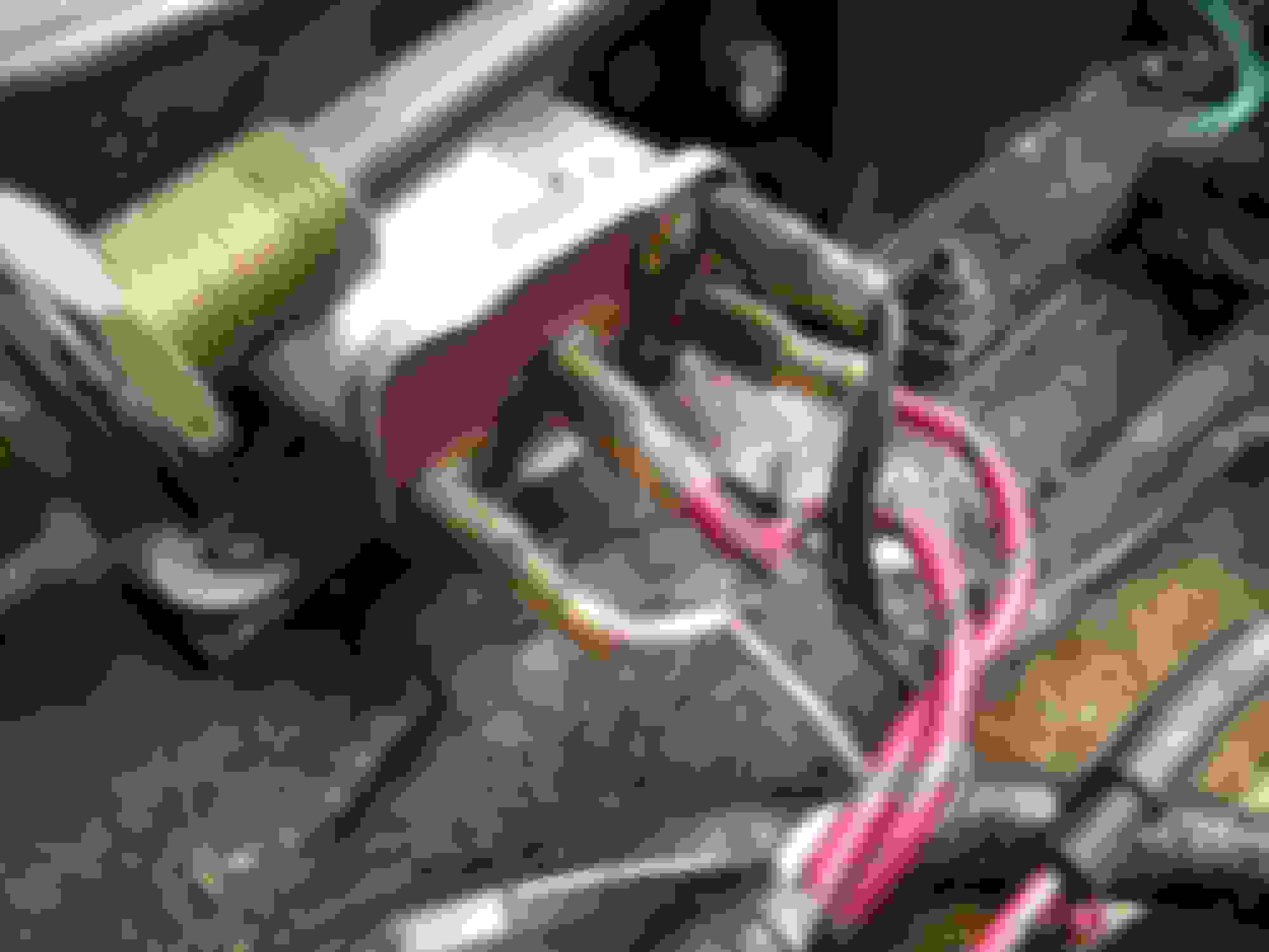
I follow the implied logic (and extracted points from Dave's posts too) but when I look at the arrangement of wires in this console and dash it seems counter logical; the thermal breaker on the dash has a RS and heavy Brown wire go into it, the RS snakes back to the Relay by the stick onto C2 I think but then C1 on the relay travels out to a dead-end (W1 has a white/pink and w2 a black as seen in picture). even if the relay was patched correctly to the power window controller buttons I still can't make sense of why one would have the breaker at the start of the circuit with a 12v load coming in on the other pin. surely it needs to be in the middle of two RS wires controlling power to the buttons or the relay so it can break upon an overload? how else would it detect the overload I wonder.
thanks for taking the time all the same, i followed most of it. i wonder why they didn't locate the thermal breakers closer to the relay and door controller under the console. the logic escapes me a little.
I being an optimist beyond reason on behalf of Lucas Lord of Darkness
Assuming that the sole function of the relay then is to deny power to the window controls when ignition power (white/pink) is not present? would that be right.
Still seems strange the breaker is not closer to the window controls directly in the circuit.
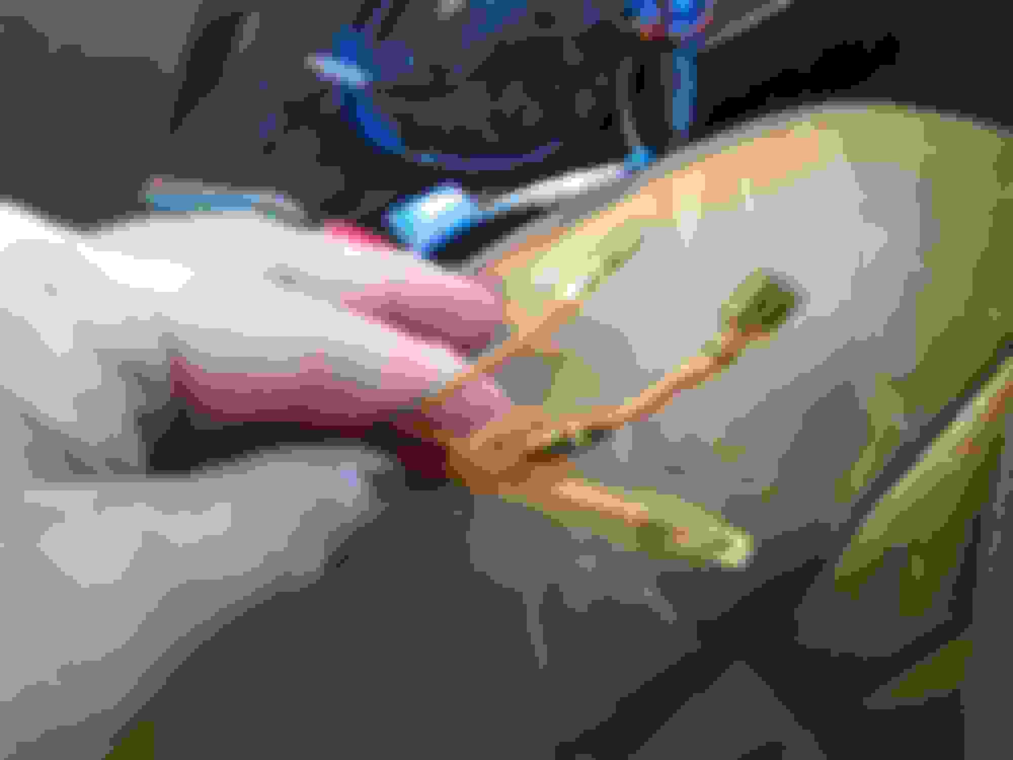
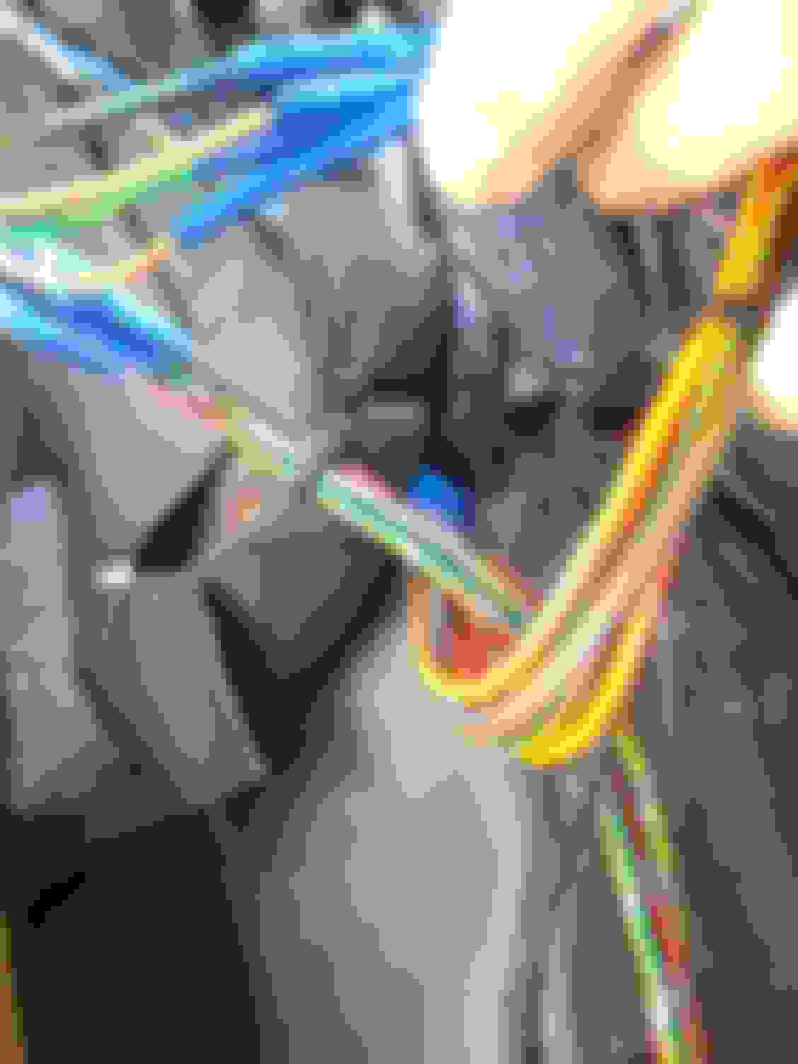
Using the same pattern i used to make lucas-sense of the power window set up I tried to explore the path of the wires for the locking switch starting at the dash thermal circuit breaker with it's brown and brown-blue wires and tracing the brown-blue on it's journey to the console. I can spot it at a few points but nowhere does it emerge to a spade to plug into the locking switch, instead it decides to vanish into the floor behind the gear cables and stick. i wonder where it was headed, not the switch at any rate. the continuity on the orange-red and orange-green wires that control the locks in the doors is bizarre as they seem to cross over colours and don't seem to go in the right direction.... these guys seems very bi-diretional at the dash position of the thermal breaker cable in front of stick shifter. cable joint by window relay... and vanishes into the floor

 04-30-2021, 01:12 AM