When you click on links to various merchants on this site and make a purchase, this can result in this site earning a commission. Affiliate programs and affiliations include, but are not limited to, the eBay Partner Network.
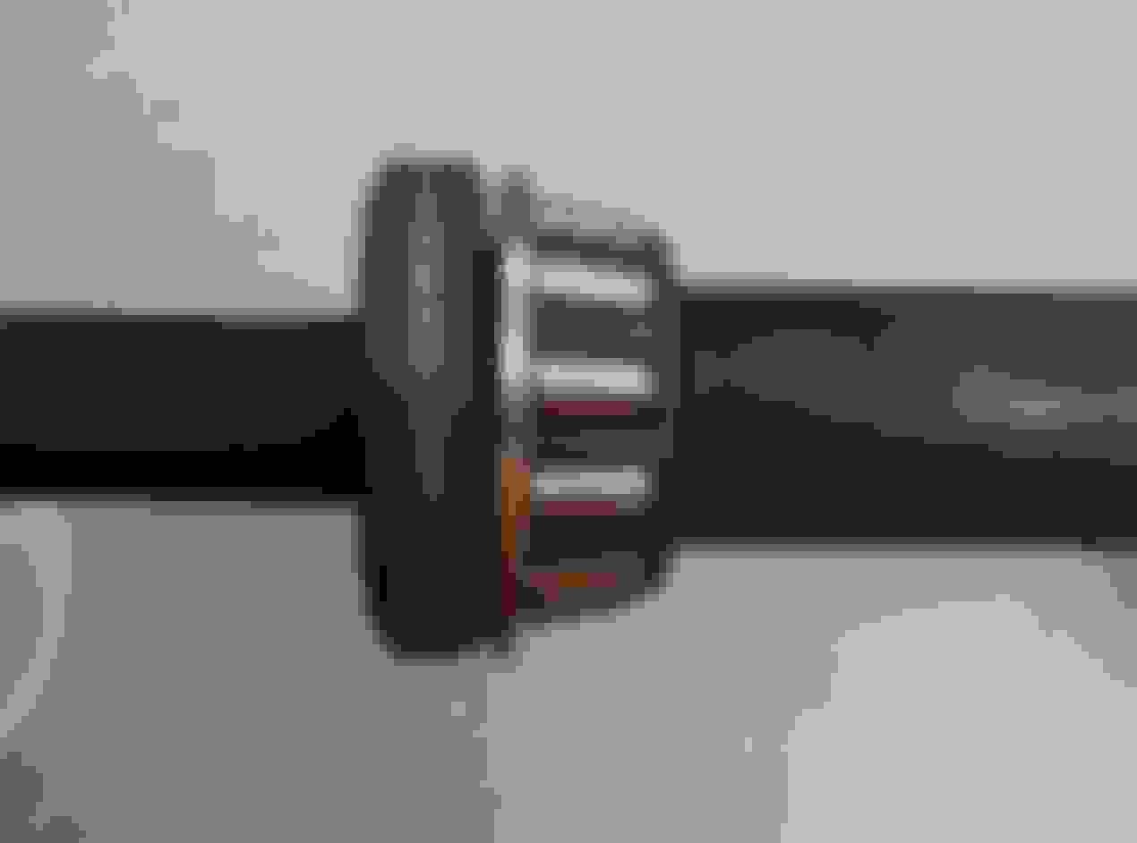
Hey guys, I'm in the process of mounting my rear hub. I was looking for information to help re assemble and I'm not finding anything using the felt oil seals like mine had. here are some pictures of my components. I'm guessing outside washer, spacer then shim and felt seal around the spacer. Then assembly with felt facing bearing?
You are holding it correctly in the first picture. Should be another washer on the back that goes against the bearing. Here's a pic from my shop manual. Do you have a shop manual?
Just in case you are not aware, if you are using new bearings etc, the key thing is getting the bearing preload correct. This can only be done by assembling the bearings etc into the hub and then measuring the endfloat. I seem to remember you need about 2 to 3 thou of preload, (ie when assembled and bolted up the inner races of each bearing should be ever so slightly clamped into their outer races by the cumulative length of the spacers and tube in between). So what has to be done is measure the endfloat with no shims, then add enough shims to the spacer tube to produce the required preload. New kits should come with various sizes of shims to do it.
Getting the entire stack of shims and tube into the hub is fun and games as they want to fall out, etc etc. Grease is helpful to hold them, and some people use a dummy shaft that is pushed out a the real assembly is pushed in.
Last edited by Greg in France; 11-08-2021 at 02:28 AM.
Just in case you are not aware, if you are using new bearings etc, the key thing is getting the bearing preload correct. This can only be done by assembling the bearings etc into the hub and then measuring the endfloat. I seem to remember you need about 2 to 3 thou of preload, (ie when assembled and bolted up the inner races of each bearing should be ever so slightly clamped into their outer races by the cumulative length of the spacers and tube in between). So what has to be done is measure the endfloat with no shims, then add enough shims to the spacer tube to produce the required preload. New kits should come with various sizes of shims to do it.
Getting the entire stack of shims and tube into the hub is fun and games as they want to fall out, etc etc. Grease is helpful to hold them, and some people use a dummy shaft that is pushed out a the real assembly is pushed in.
This side is not getting rebuilt. I'm just replacing with the parts that came off. These outside parts were removed before I could note orientation.
Hi, here are a few pictures I took while rebuilding my IRS. I don't have my notes handy but seem to remember something about the parts diagram being misleading or not quite in the correct order. It may have been the descriptions of the parts, too tired from work at the moment to remember. I'll dig up my notes and try to post more details tomorrow.
You will definitely want to remove the bearing retainers ( my popped out with just a screwdriver ), the bearings and center distance tube for cleaning. The guts of my carriers were full of petrified grease and the tube looked like, well lets just say something inside a bad porta-potty ! Not going to post those pics !
I modified ( sealed ) the grease vent holes on the inside of the hub carrier by tapping it for a small screw ( 4-40 maybe ? ). If left "stock" when greasing, all the new grease goes out the hole and fills up the wishbone tube and none goes out to the bearings and felt seals. You do have to be careful not to over grease when servicing, theoretically could blow out the felts if you get carried away. Think I found the trick in Kirby's excellent XJS book.
The pictures show all the parts in the stack spread out on the shaft then together. Also shown is a pic of everything in the carrier prior to installation. You can see the piece of hose I used as a dummy shaft to keep everything aligned until assembly. There is a zip tie going through the hose and around the outside of the carrier to prevent anything from escaping. If you don't use a dummy shaft the inner shims can shift over quite a bit blocking the installation of the shaft. I also prefilled the inside of my carrier tube with grease, prepacked the bearings, installed them with the center distance tube with dummy shaft / hose, then used my grease gun on the fitting to expel air until grease started to come out of the bearings. I then fitted the outside parts, greasing everything including the felts before installing.
Important note ! The inner shims control the load on the bearings, the outer ones control the fit of the carrier in the wishbone so the number and thickness of both could vary on every car. I believe the operations to check both are in the Service manual, getting too tired to go look right now !
Here are the pictures, hope they help.
Felt "seal", seal retainer, seal center, carrier width shim felt and stack, inside end up stack together, inner side is up, outer side down
all parts of one side in order. Will try to make a labeled version tomorrow. All loose on shaft to see order, this side has 2 width shims and 6 bearing load shims. Tight stack
Rebuilt hub carrier, notice hose dummy shaft with zip tie to hold everything, screw sealing grease vent is visible in center.
Last edited by kudzu; 11-08-2021 at 10:26 PM.
Reason: adding picture
One last note for tonight, I reused all the parts including the felts after a thorough solvent bath & re-greasing. The shims you have in your pictures are for the fit of the carrier in the wishbone and should go between the bearing and inner seal track or retainer ( think that's what it's called, should be one shim per side. That's so the carrier is centered inside the wishbone and doesn't rub it while moving -- my best guess anyway ! )
It's not a very good design using taper rollers, because these are made on the assumption there will be continuous rotation, or at least rotation over a significant sector, but on the trunnion, the movement is very small in degrees. What this means is that wear takes place in a very small part of the bearing tracks, and they can even suffer from brinelling because of this. Having said that, they do manage to last quite a long time, longer than the stupid bushes on the wishbones of the X350s I had !
Hi,
I made a diagram with part numbers using a CAD image I THINK came from Kirby's XJS book ( please correct me if I'm wrong, I'd like to give credit to whoever made it ! )
Be careful if you order shims, the inner and outer shims all have the same base number just different /#'s even though they have different outside diameters !
The thickness spec for the width shims is .003 or .007 but mine all measured .004 when removed because of the slight lip from being stamped out of flat shim stock. When installed they should flatten down to .003 ( in case anyone else measures theirs )
Some more notes, mine had 2 @ .003 width shims on the left side ( one on each side ) and 3 @ .003 width shims on the right ( two on rear side, one on front side )
The left side had 6 @ .003 bearing load shims and the right had 7 @ .003
Interesting side note ( to me at least ), all the bearing load shims where between the left side bearing and the center tube when looking at the hub carrier from the outside. Makes me think the factory had a set procedure for adjusting the carriers during IRS cage assembly so they always put the shims on the same side.
Here's the diagram I made and printed to insert into my parts manual, I just upgraded it with readable photo editor call-outs instead of my hand scribbles !

 11-07-2021, 02:36 PM