When you click on links to various merchants on this site and make a purchase, this can result in this site earning a commission. Affiliate programs and affiliations include, but are not limited to, the eBay Partner Network.
Bry5on, looking at the pictures in #1 post, I didn't get a center support mounting plate as I see in your 3rd and 4th pic. Is that stock? It looks like something that can be fabricated from 1/4" plate, am I right?
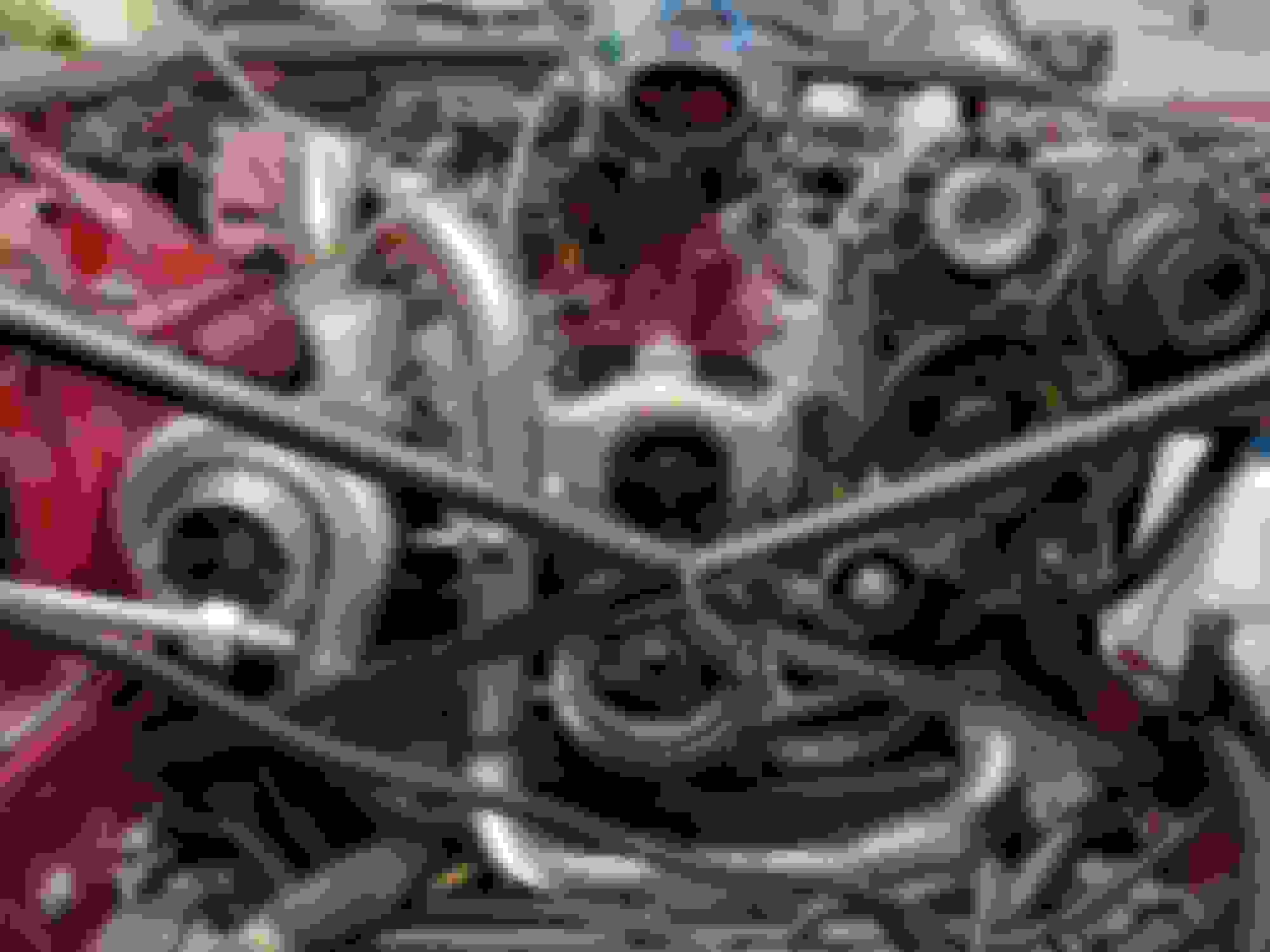
This is my solution. Area where brackets are, were doubled on the inside, when I did the floors Not the prettiest solution but rock solid. It should hold front to rear, and side to side as well.
This is my solution. Area where brackets are, were doubled on the inside, when I did the floors Not the prettiest solution but rock solid. It should hold front to rear, and side to side as well.
I dont this this will work all that well, and its certainly not ideal. It will still allow the cage to twist up. The part of the cage that is connected to the additional struts tends to move up, not forward. If the mount points were on the lower part of the cage about 3 to 4 inches further back it would work great. As it is, the leading edge will still tilt up quite a distance with minimal change in length of the strut arm. Also that appears to be an aluminum plate, that will certainly flex under the forces that are at play here.
The more I look at it the more i think this design might be dangerous and create unpredictable handling. As the cage moves up those joint will quickly bind and the struts mounts will act like leaf spring, then the joints will unbind and the spring forces will release as the upward force on the cage subsides. This may cause snap like movements when on and off the power creating rapid toe change that may not be natural.
Last edited by icsamerica; 07-08-2021 at 03:17 PM.
JACOBRA, I believe the assessment from icsamerica is correct, from a geometrical and functional stand point. You have some heavy duty parts and pieces welded/bolted in place, but the type of rod-ends you're using are meant to handle rotational forces that revolve around, not at right angles, to the anchor bolt. A Hiem Joint is a much better choice. To me, you are a little too far forward on the imaginary line of rotation. You are getting close to the transition between the rotational force when it is purely fore/aft (directly under the diff), and when the that force is purely up/down (directly inline with the pinion). Raising the chassis anchors 6" or so, lowering and moving the cage anchors down/back as icsamerica has said, and turning your current rod-end joints 90* or substituting Hiem Joints would give you better results, IMHO.
Well ICS, as I see it you are nit picking the hell out of it. Point #1 If you look at the picture real good you will realize the radius arms I've created are virtually in line with the lower control arms. The reason it doesn't appear that way is the car is on a lift and the rear wheels / axles are at full extension down ward. As it is IRS, the cage is still in the normal position. when the car is back on the ground. You will find the radius rods are almost perfectly parallel to the rear control arms So there should be no binding whatsoever. Point #2 beings the front of the cage where I have attached the plate, and by the way it's not aluminum, it is steel. If you look you can see the weld in the center. The shiny edge is where I cut it in half to make a piece long enough out of what I had. The 2 pieces were V'd on both sides fill welded, and the ground smooth, only the edge wasn't ground smooth, thus you can see the edge where it was welded. Point #3 The front edge where I attached the radius rods, is effectively about 6 inches below, and 6 inches in front of the pivot point / axles. This is where it will try to rotate on the axles. and since I am, approximately 6 inches below, and 6 inches ahead of the pivot point. The cage will indeed rotate up, but the lower front edge, must also come forward! Which is where the radius rods will limit the rotation, and thus the rise. I used rubber bushed rob ends, so as not to transmit vibration / noise from the cage / rearend to the body. Which is why Jaguar mounted the cage in rubber in the first place. A heim joint allows movement on several different axis, and transmits vibration, and noise from one component to another. Rod ends tend to limit movement, and do it quietly. That being said, Unless you have a degree in Mechanical engineering??? I'd almost bet, I know a little more about it then you do. Sorry to sound a little Snarky, but ICS has busted my chops a couple different times, on the build of my "Jacobra". And it's been a bit more then just pointing things out. Corrective criticism, is welcome, and invited. Snide comments are not appreciated.
Jack, my post might have seemed a little harsh, now that I see some past history. I stand by everything I posted, but I'm not trying to be adversarial, only give you my point of view.
The setup you show in the pics will reduce cage twist to a certain degree, and that degree could very well be what you are looking for-no problems. I tend to "pick the white out of chicken ****" when I comment on certain issues, nit picking might be a good term. If what you have done works for you, that is absolutely the name of the game. However, I have to comment on your "torque rods" and the Jags radius arms. The factory radius rods at the outer ends of the lower control arms are not there to control torque-twist on the cage. They strictly resist the fore/aft force created by tire traction. The inner bearings of the lower control arm and the highly leveraged outer hub carrier connections are all that make the car go down the road. Sometimes, every little bit of help we can give them is worth it.
Hey Dave you are correct in that the control arms are controlling the Hub carriers. which due to traction causes forward movement. In turn that traction causes the differential to rotate in the opposite direction. A cause and effect kind of thing. All my radius rods are doing is limiting the rotation of the differential, which will have the same general effect as traction bars / ladder bars, like we used to use in the 60' and 70's to control axle wrap / rotation of the differential. With the Jag being IRS there is no axle tube to mount traction bars to. So the next best thing is to limit the rotation of the differential itself. Which is exactly what I have done. Bench racing as we call it over here is a way to work through things, and get a chance to explore your ideas, along with opposing views from your friends, and others who are knowledgeable. and that is what it's all about. Not one person can know everything, and the next guy may know what you don't.
I am currently in contact with Ward engineering in the uk, they are a jag axle place, he has polyurethane bushings for the rear cradle, however is concerned that if I stop the current flex, something else will flex, and is concerned that I will crack the cradle, am I /are we worrying for nothing? Im
not putting done that much power, not nearly as
Much as the electric one the original poster is…., I would estimate maybe 350 Hp, no clue of torque!!
I'll offer my opinion again Darren, and that is to stay away from poly bushes in that particular area. I'm with the people at Ward Engineering, the cage is not as strong or rigid as a straight axle and has been designed to have a little "give" in the mounts so that it doesn't have absorb all the flex. Remember, these are 35-50 year old luxury touring cars (think of the Queen when you consider how Jaguar wanted it to ride). I think it would crack over time if it were leaned on with any regularity. I used poly bushes in the front suspension and the small end of rear radius arm. I don't consider those joints being strained with the poly bushes, but I'm not sure how I will feel about the ride once it's on the road. Stick with rubber bushes on the cage and add some type of torque rod(s) to hold it where you want.
FWIW, if you went to a one-piece driveshaft, you probably went to a larger diameter. The stock rear section of the driveshaft is about 2" in diameter and somewhere I read that clearance in the tunnel was the reason. I am going to stay with the 2-piece design for this reason as well as the claim that a 2-piece usually runs smoother than a 1-piece. I will replace the composite front shaft with a standard piece, probably a little bigger diameter. Much more tunnel room up there.
Well ICS, as I see it you are nit picking the hell out of it.
Jack, analysis based on ACTUAL experience is not nit picking. Lengthen those rods 4 inchs and mount them to the bottom the cage and you'll be far better off. You don't even need to redo your mounts and you can just roll in some arch.
I'm probably the only person running these cars at this level and talking from experience on the track at well into triple digit speed running down much newer cars. My current engine is next level (700+ hp) and I've already started testing it in the car.
I am currently in contact with Ward engineering in the uk, they are a jag axle place, he has polyurethane bushings for the rear cradle, however is concerned that if I stop the current flex, something else will flex, and is concerned that I will crack the cradle, am I /are we worrying for nothing? Im
not putting done that much power, not nearly as
Much as the electric one the original poster is…., I would estimate maybe 350 Hp, no clue of torque!!
darren
Ward are correct, because of the geometry of the rear axle - when the rear suspension moves the radius arms travel through a different arc than the wishbones - the rubber in the radius arm bushes, AND the cage rubbers allow this to happen with no stress to the cage. This also produces rear toe-in changes which are part of the handling characteristics of the car, and which make it safe and predictable to drive.
The OEM setup can carry 350 BHP, unless you have drag-strip sticky tyres and hooligan it all the time!
If you need to support the cage more, then extra rods with rubber bushes as explained in the Jacobra part of the thread, suitably located, are the ace way to fix the problem.
All solid cage mountings will do is make the cage steel bend instead of the bushes flexing.
Interestingly, on the racing TWR XJSs, under the guise of it being an anti-roll bar, they actually changed the rear axle radius arms and relocated their ends in line with the inner lower wishbone fulcrums, so that they did move though the same arc as the wishbones, and thus allowed their solidly mounted rear cage to be stress free when the suspension moved.
Jack, analysis based on ACTUAL experience is not nit picking. Lengthen those rods 4 inchs and mount them to the bottom the cage and you'll be far better off. You don't even need to redo your mounts and you can just roll in some arch.
I'm probably the only person running these cars at this level and talking from experience on the track at well into triple digit speed running down much newer cars. My current engine is next level (700+ hp) and I've already started testing it in the car.
Well it seems you might know something about this after all. 700+ hp is nothing to sneeze at. and will definitely put enough stress on things to find the weakest link in the chain for sure. I'm on the other end, as I have never Hot Rodded a Jaguar before, and some of the things I'm doing, are trying to be as simple, and straight forward, as that is usually what works best? As I've stated before in the write up on the "Jacobra" everything is subject to change. As I find out what works, and what doesn't. Back in the mid to late 70's we had to make everything back then, cause there weren't Specialty Manufactures. Building suspensions, chassis, wiring harnesses, etc. etc. And since you and I have undertaken a "Foreign Object" (Jaguar) as to what is considered the norm Muscle Cars, and we decided to dare to be different. Were back to square one as nobody does what we are doing. It's a whole new learning curve, where obviously your are a little ahead of me. If it's easy, we'll do it right away. If it's impossible? It will take a little bit longer!
A two piece driveshaft will still cause grief with forcing the diff flange upwards towards the tunnel. The cage cannot handle high torque without extra support.
I am currently making 650 pounds of torque with a single piece shaft and have used a 200mm wide, laser cut 3mm thick, spring steel tie plate that links the bottom of the diff to the foreward chassis tunnel area via the old two piece tunnel mounting bolts. This stops the flange heading skywards with the spring steel giving a little bit of shock absorbance.
I am also running racing bushes in the rear trailing arms in order to keep the diff position in check.
The car handles fantastic and is seriously fast!
it works very well and has no problems at all.
Without the plate, it is impossible to keep the diff cage in place unless you solid mount it to the chassis.
I am not running wide tyres so my setup breaks traction with ease if I feel the need however launches extremely well if i feather it slightly.
I am amazed at how well it handles the power and expected a loose, dangerous ride but it’s seriously well behaved.
If you have fat grippy tyres for drag racing you may need to go to a thicker plate.
if you would like the cutting files for the plate you can message me.
Last edited by Crackerbuzz; 07-26-2021 at 03:13 PM.


 07-06-2021, 06:29 PM