When you click on links to various merchants on this site and make a purchase, this can result in this site earning a commission. Affiliate programs and affiliations include, but are not limited to, the eBay Partner Network.
Area where brackets are, were doubled on the inside, when I did the floors
Not the prettiest solution but rock solid. It should hold front to rear, and side to side as well.
Hi Jacobra,
I think this looks like a reasonable solution and your solution will definitely stop upwards thrust from the diff flange. (I am guessing you have trialed this with success?)
The only thing I can't see is if the connections are rubber bushed or not which will help with noise transfer. (My spring plate is not rubber mounted at the forward connection though, but seems to be quiet enough for me)
I like the sandwich plate-mount that Lickahotskillet used on his rear connection. This would allow for complete body insulation. Maybe he can comment on how good the sandwich mount has been?
I think you will get some success with this to a certain point, but your fixation points are set very wide which will not allow for any pivotal movement in the cage which can help with handling.
If you have a more centered fixation, the cage can still rotate around its axis slightly assisting the handling characteristics which is generated on cornering.
With a factory setup during a hard right hand bend for example, the left rear suspension is pushed downwards causing the trailing arm radius to shorten by default.
This allows the cage to act like a pivot around the rubber cage mounts causing a slight four wheel steering effect which improves steering and handling.
With the slight flexibility in my spring plate assembly (which is installed with a slight S-bend configuration for compression movement) and mounted centrally, the cage still has the slight ability to rotate, albeit a little less than factory I would imagine.
I will get some photos tonight.
Cheers
Craig
Last edited by Crackerbuzz; 07-26-2021 at 09:03 PM.
Note, this is for a series two coupe, but you can roughly check these measurements to make sure your bolts holes are already in place around the rear tunnel area. (Note the measurements wont be exactly in a straight line as the plate is mounted in a S-bend configuration)
I am not sure what the series 1 and series 3 configurations are like, but imagine they will be different to the series 2, likewise with an XJS.
I can supply the "cutting" file than you can give directly to your laser cutting contractor...
I wish I could tell you I've tried this out, but not yet. I'm a lot slower with things then I used to be. And yes the strut arms are rubber bushed at all 4 ends, which should squelch vibration, and yet allow the wiggle of the cage you were describing, without it getting to far out of whack. I just finished all the floor repairs inside, and undercoated them. They are now ready for the Boom Mat / insulation as It's called. So I'm getting closer. Then I have to move the dash, wiring, heat, and A/C from the parts car to mine. Before I can finish the engine and drivetrain. Still having fun with it. But it did me a lot of good, to get the interior floors completely done. as I was needing to complete something for my own Sanity! LOL!
I dont this this will work all that well, and its certainly not ideal. It will still allow the cage to twist up. The part of the cage that is connected to the additional struts tends to move up, not forward. If the mount points were on the lower part of the cage about 3 to 4 inches further back it would work great. As it is, the leading edge will still tilt up quite a distance with minimal change in length of the strut arm. Also that appears to be an aluminum plate, that will certainly flex under the forces that are at play here.
The more I look at it the more i think this design might be dangerous and create unpredictable handling. As the cage moves up those joint will quickly bind and the struts mounts will act like leaf spring, then the joints will unbind and the spring forces will release as the upward force on the cage subsides. This may cause snap like movements when on and off the power creating rapid toe change that may not be natural.
With all due respect, in order for the cage to rotate upwards, it MUST move forwards as it is trying to rotate via the centre point of the IRS rubber mounts.
Jacobra's arms will prevent forward movement, hence prevent upwards movement.
The principal is similar to my installation which is perfectly adequate.
I think it will work, but time will tell and we will find out in due course!
Jacobra, please keep us posted on the outcome.
Last edited by Crackerbuzz; 07-27-2021 at 10:55 PM.
To be fair that's a bit hard to tell right now, as my interior is not quite completed and the carpets are not installed, along with a pretty hefty V8 exhaust which is definitely louder than the original engine...
But the answer would be nothing of any major noise coming through so far that has even made me think of it.
No vibration at all. If I do notice some noise after the interior is completed, I may look at a sandwich mount similar to Lickahotskillet, but it has be specifically designed for shear forces which I am not sure they are designed for.
If you are reading this Lickahotskillet, can you comment on the durability of your sandwich plate?
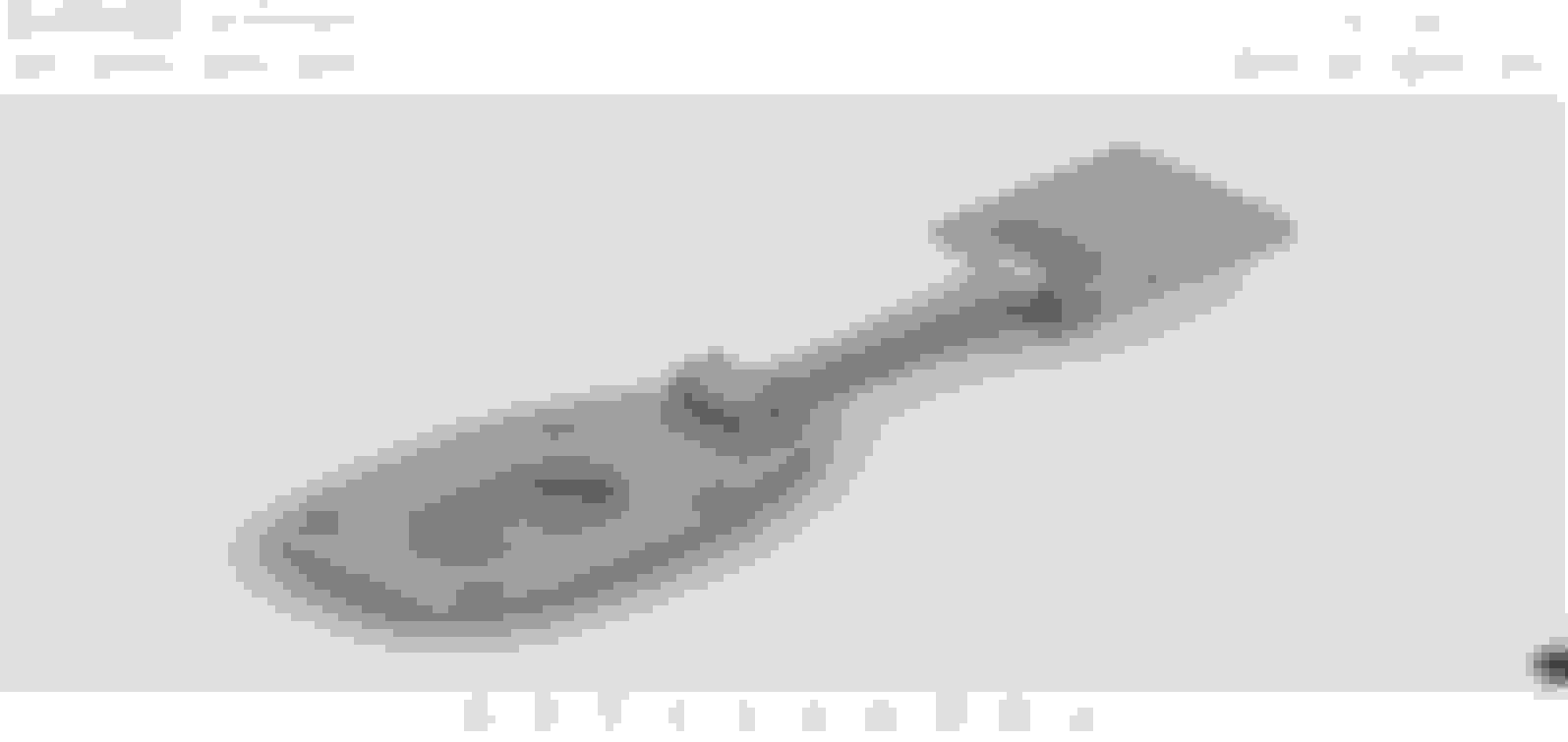
The design was Rob Wade's on J-L. The plate I had made does not bend, or likely flex. The plate replaces the factory sheet metal that was the bottom of the cage. All the cage rotation is taken up with the urethane transmission mount - chevy or ford, can't remember. It moves enough that the 2 1/2" single piece drive shafts stills rubs the heat shield (asbestos factory shield). Trunk is reinforced were the mount bolts up.
Handling wise: it launches straight with power brake to 3000 rpm. Was predictable on Mid Ohio Sports Car Course. I did over correct in turn one when I should have just let her drift wide. It spun out. It has a slight toe in on the RR from a PO accident. It will go left if you punch it at a standstill. Has nothing to do with the plate.
The cage has the SNG premium cage mounts, all new bearings in the pivots, SNG lower arms with Urethane bushings, each axle hub was rebuilt, and a XJS 12 sway bar installed. Installation was done in December of 2012. just went to the garage to look - no signs of the mount tearing. Car only gets flogged in the summer.
rear view
Left side of boot
Right side of boot Front view
Last edited by lickahotskillet; 07-28-2021 at 04:50 PM.
Reason: additional picture
LAHS
Is the mount attached to the trunk floor (ie going rearwards from the diff) or forwards and attached to the cabin floor? I cannot quite see from the pics.
LAHS
Is the mount attached to the trunk floor (ie going rearwards from the diff) or forwards and attached to the cabin floor? I cannot quite see from the pics.
. It moves enough that the 2 1/2" single piece drive shafts stills rubs the heat shield (asbestos factory shield). Trunk is reinforced were the mount bolts up.
This still rubs because the whole back 1/2 of the car flexes. The torque from the diff is pulling the back 1/2 of the chassis downward. The over the axle boxed sections are very weak on XJ's and XJS. Most of the sheet metal back there is just along for the ride. The XJ coupes that raced cracked as the base of the C pilar. And becasue of this the XJS flying buttresses and thicker A pillar were developed to tie the back 1/2 of the car into the roof. The XJS was a further development of the XJ chassis and those rearward flying buttresses were developed to help solve this problem by triangulating the area.
The correct way to solve this problem is the way Aston Martin, Jaguar and the other successful race teams did. Look how Jag solved this problem on the XJ40 too.
Here is a fully bushed solution that works on the street and track. You can still see witness marks where my drive shaft used to rub. The bushing is the urethane version of the small trailing arm bush pressed inside a small section of standard DOM tube.
1. Notice how far back from the leading edge the IRS attachment point is. This give mechanical advantage to the bar
2. The Curve in the bar helps keep the mechanical forces against the bar in compression where tubing is strong. (No bending forces). The curve is subtle but very necessary. The first one I made didn't have the curve and did not work as well.
3. Notice the lateral tie bar which helps the tunnel stay in square. (being improved, A large and dimpled died plate that uses all 4 mounting points is in progress)
Out on the track this works well. The car exhibits text book and predictable driving dynamics... on throttle over steer and throttle lift tuck in. The whole contraption is about 4lbs. Every LB counts.
In the 700HP version of this car, I'm back to a 2 piece drive shaft and the center bearing is mounted to the new plate just like Jag did with the OE 2 piece shaft.
Last edited by icsamerica; 07-29-2021 at 10:43 AM.
ICSA
I do like the look and simplicity of that mod. A few questions if you have the time:
Is the rear end of those round tubes attached to the diff bottom tie plate?
What are those diagonal bars doing, are they bracing the cage for lateral forces?
Are the bars and the tubes in rubber bushings at the car body ends?
ICSA
I do like the look and simplicity of that mod. A few questions if you have the time:
Is the rear end of those round tubes attached to the diff bottom tie plate?
yes uses 4 existing bolts. I'll try to get a better pict when I'm under the car this weekend.
Originally Posted by Greg in France
What are those diagonal bars doing, are they bracing the cage for lateral forces?
Are the bars and the tubes in rubber bushings at the car body ends?
the Lateral X bars don't attached to the cage at any point. They stiffen up the rear chassis / frame which moves around on the coupe and sedans.
The Aston Martin DB7 had a similar X brace and the IRS did attached to the middle of the X brace. I do have an AM DB7 brace and all the hardware but I'm not currently using it. It's substantial and kind'a heavy so on balance what I have suffices for a lower weight.
Last edited by icsamerica; 07-29-2021 at 01:12 PM.
After finishing a decent chunk of the interior which has quietened things down a lot, I have now noticed a slight "whirring" sound coming through the floor from my spring plate which increases an decreases evenly with speed. (must be the diff gears slightly coming through)
It is only minor, but enough to be a little annoying so I have V2.0 almost installed and will update on how successful this one is.
The new design uses 4 x stock rear radius arm bushes.
Fascinating thread, lots of innovative solutions here. I too am fighting some cage movement that is allowing the driveshaft to kiss the inside of the tunnel during high torque events. I am working on my own solution that is fairly simple and should limit movement while still allowing full range of motion during cruising, cornering, and braking. Should have some photos of the progress in the next few weeks.

 07-26-2021, 03:01 PM