When you click on links to various merchants on this site and make a purchase, this can result in this site earning a commission. Affiliate programs and affiliations include, but are not limited to, the eBay Partner Network.
Thanks for the super detailed rebuild job.
Its great to see progress being made.
I really liked how the cam covers came out. Is there a clear coating you can use to protect the alum that you sanded? I remember cleaning mine up years ago and in short order the Alum began to dull up.
Bobmo
I really liked how the cam covers came out. Is there a clear coating you can use to protect the alum that you sanded?
There was a discussion about this on one of the other forums, specifically for the older cars with the fully polished covers. The consensus was there was nothing that would stand up to engine bay temperatures without yellowing or peeling.
Great to see some more progress...just that much closer to the end.
...well, we both know it never ends, but you get my point.
Only thing I'll add is when doing a "leak test" on the valves, use a solvent...not terribly important what you use, it's just that water has a fairly high surface tension, and can actually hold fast where a solvent will leak through.
It makes a difference.
...and plus 100 on getting the block properly flushed - the peace of mind when it's done is well worth the extra work/expense.
Looking forward to seeing more completed tasks mate!
Mmm yeah, probably would be a little more leaky with a solvent, I hadn't thought of the surface tension of the water, but thats a very good observation.
If I was able to find a finer grit I would have gone one more time over it, but I think (though first time lapping valves) that its probably must better than it was so thats "probably" good enough for a rebuild of this level of detail, well I hope so anyway!
Originally Posted by bobmo
Thanks for the super detailed rebuild job.
Its great to see progress being made.
I really liked how the cam covers came out. Is there a clear coating you can use to protect the alum that you sanded? I remember cleaning mine up years ago and in short order the Alum began to dull up.
Bobmo
Originally Posted by Jagboi64
There was a discussion about this on one of the other forums, specifically for the older cars with the fully polished covers. The consensus was there was nothing that would stand up to engine bay temperatures without yellowing or peeling.
Thats a good point actually, there is a high temp VHT Engine Enamel clear coat thats meant to be good up to 288 degrees C.
But I'm not sure if it'll do well directly on the Aluminium. Its not cheap either so I think I'll leave it as. I guess I can always taken them off and give them a wet sand to polish them again in the case that they look tatty.
Next on the agenda is the block, it's coming out.
I dropped the oil and removed the power steering pump and the alternator last night, so thats a start.
Heres my plan currently, based on my research:
1. Support the trans (staying in-place), safely support the car etc.
2. Loosen all bolts to find any that might be a battle - Engine mounts, bell housing.
3. Take the trans oil cooler pipes off the brackets on the intake side of the block - If anyone knows how these are attached to the trans then that would be great because they will be in the way.
4. Oil filter off, and if I cant get the above pipes off, also the Oil filter mounting block thing, because they are interlocked.
5. Flex plate bolts, which I'm not fully sure how to access, I think through the starter motor hole? - Advice?
A. I hope that the rattle gun will loosen these, otherwise I might be in a bind trying to stop the trans from spinning.
B. Is there anything else that I should loosen before removal? The bolt on the front of the harmonic balancer maybe? I guess the torque converter will spin anyway.
6. Engine crane to get it out, then final removal of bolts and out she goes. For lifting, I plan to use the exposed head studs with double nuts to hold the jag engine pick up points in place and pick up with them.
Let me know if I'm missing anything, most other systems have been removed already.
Then it's off to the machine shop to be checked and have the broken stud and the heater plug removed and a big ol' boil.
All of the bell housing bolts are cracked and ready to come out, was a bit fiddly but easy enough.
The crank bolt/damper bolt/harmonic balancer bolt or what ever you want to call it came out very easy.
I used some penetrating oil, and then a little heat on only the bolt, but not anywhere near glowing hot, I could still touch it if I was quick.
Then my little 18v cordless impact driver (165nm max) got it loose in 10 seconds after that. Maybe it wasn't as tight as it should have been.
I've also managed to loosen one of the flex plate/torque converter bolts with the impact too, so thats good news. The rest will come the same way.
Then it's basically ready to come out, other than the pesky trans oil cooler pipes, which after research appear to go to the left hand side of the trans, perhaps I can take them with the engine if I'm careful.
I was fully ready for the battle of a life time with that crank bolt so I'm very happy about it just coming out nice.
Though now I don't have a plan of action for the weekend. Ill come up with something that can be done.
I've finished lapping in the new valves and did the water in the cylinder dome trick to check for any terrible leaks. Found a few that needed a little more, did those and no more leaks.
Though the "fine" grit wasn't that fine, I'm sure you could go further, but I don't see the point really, I just want it to run reasonably.
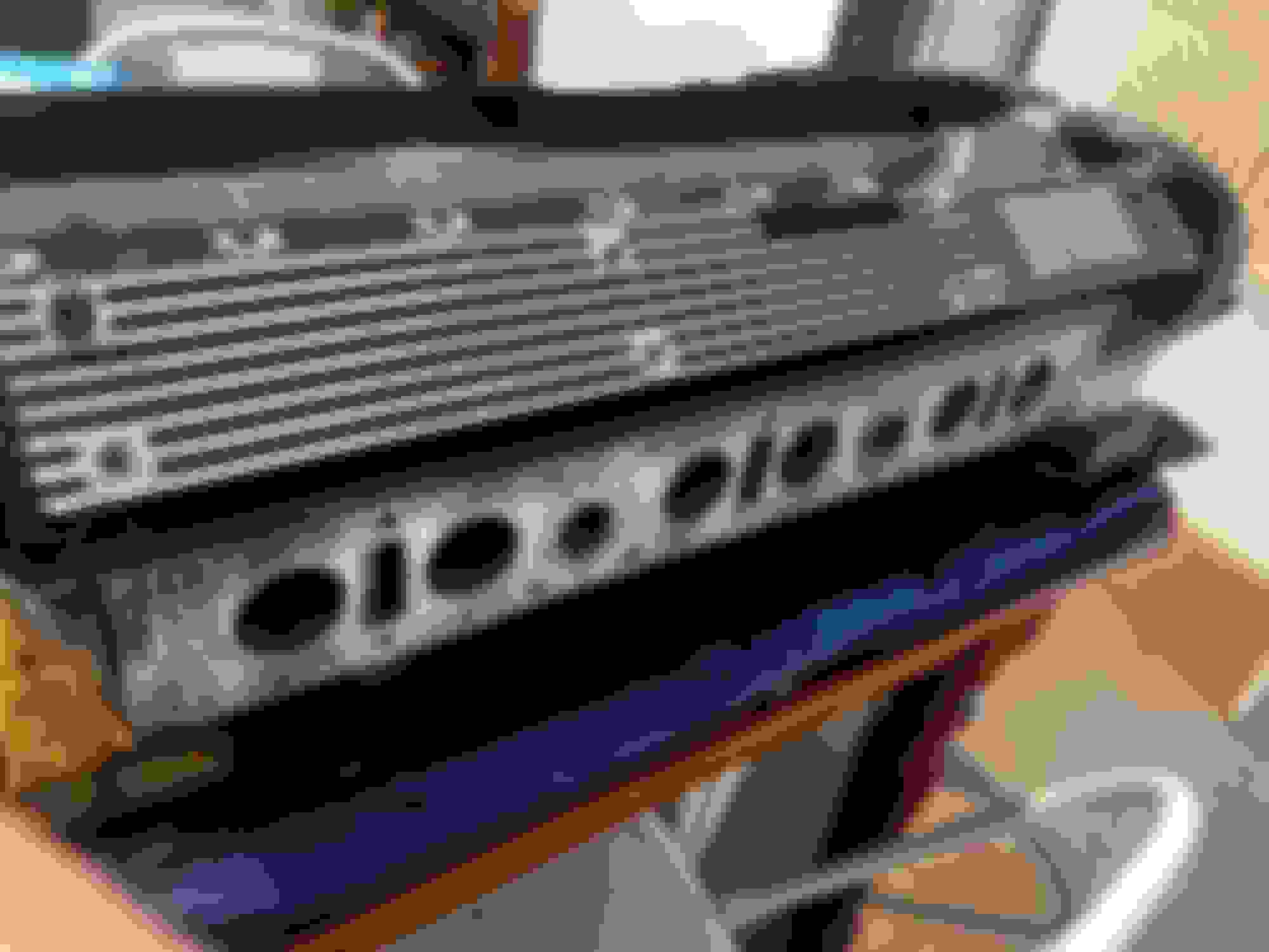
Next on the agenda was painting the cam covers, I've done this is VHT engine enamel in satin black, and then baked it with 2400 watts for 4 hours of lamps in an attempt to cure it a bit before sanding.
They got very hot but not uncomfortably hot where I was worried about the aluminium. Might have been a pointless exercise.
I started to sand by hand but honestly it was just way way too slow, so I ended up using the flat orbital sander on it. Which worked well, but I wouldn't suggest that for a show car as there was some chips of paint that came off around the edges.
160 grit to start, then finished with a 1200 grit wet sand, all on the orbital. - Do it by hand if you want perfection and probably go higher than 1200 grit.
Looks pretty good though:
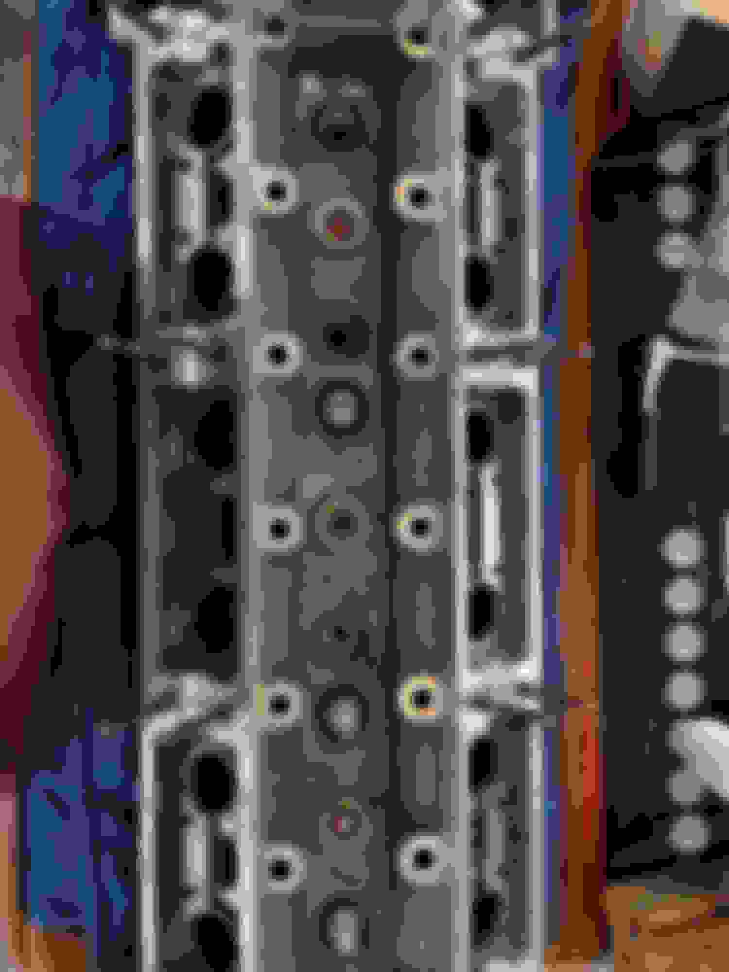
Oh yes, I installed the tappet guide stake down kit also, on both sides, heres MY method for anyone looking. It may not be the best but it worked for me.
Firstly, you CAN drill right though if you are tapping a thread, it's just another oil gallery. BUT I wouldn't do this with the head on the car due to the shavings.
I've seen some suggest that it's ok to do, but the valve stem guides are right there and it just doesn't seem like a good idea to have those shavings washing around in there.
I preferred the drill through method because you know that your tapped thread is going to be long enough for the machine screw.
Spoiler
Any more updates after this? I am glad I found it in your post. I also very happy because while searching for it online, I also discovered https://casinosanalyzer.com/online-casinos/fast-payout website link where I found those sites through which I can make easy money. Now, I don't have to go anywhere to earn money.
First I placed all the plates and taped them firmly into place with gaffer tape, taped all openings and cam bearings.
Centre punch in screw hole for a drill guide.
Drilled right though - which for reference is roughly 25mm measured from the TOP face of the plate in place - ie set your depth gauge (or bit of tape) at 25mm and you'll probably go through.
My kit from XK unlimited needed a 10 - 24 UNC thread. Which is the same as 3/16 UNC apparently, using kooky imperial math.
I left the plates in place while I cut the thread, this gave me a useful guide as to if I was reasonably square. Dont for get to be square in vertical and horizontal axis.
I used a tapered tap to start and then a bottoming tap to finish, which I would also suggest.
Then blew it all out with compressed air.
I also used a cheap Chinese endoscope to watch the drill bit come through, though you can clearly feel it. It was a nice piece of mind having inspected the area below before starting work.
The interior looks like this for those wondering:
You come through that top face if you drill right through, plenty of space and nothing to hit.
Valves are installed along with cam shafts and the valve clearance measured, it's mostly within spec but I'm unsure if my measurements are good because I can push in larger sizes with some force.
Just don't really know what it should "feel" like, and it's a sprung surface, leading to my questioning of my measurement.
I'll get a pro with the feeler gauges to check it for me.
For the tightening down of the camshaft, it's very nerve racking. The service manual says to start with the cam timing notch in the upmost position and tighten from the middle evenly.
However, it's quite tricky when pushing against the valve in cylinder 1 (rear most).
The cam needs to travel much further there and its hard to tell if I've done it right, lets hope its not bent.
Actually, while I'm posting, I also cleaned up the trans oil cooler, that greasy thing under the rad.
I found a pin hole in the inlet tube which would explain the mess, though I never lost much if any at all trans fluid.
Very tidy, but this is one I got from the 81 XJ6 at the wreckers, and its slightly different.
So I'll document that difference, the later one "81" is slightly longer and is lacking a coolant drain plug and the oil cooling internals are different.
On the left is what I believe to be the later longer version without coolant drain plug.
They are the same diameter despite looking different in the photo.
Great advice, I think I'll get the machine shop to heat it up and remove/clean. Or I'll asked them if dipping the block will clear that area out well enough.
I rebuilt the intake manifold, took it apart fully, cleaned and painted with the VHT engine block enamel in satin black.
This colour isn't right though, it will look good but it's too shiny and dark I think. Good enough for me but not for a concours rebuild.
I also decided to paint the positive crankcase ventilation pipe/breather pipe, because even after deep cleaning it looked dirty.
Same goes for the fuel rail, thats painted black now for the same reason, so that side of the engine is missed a few bits of shiny, but should look good.
A few other things, I found the PCV pipe was blocked, so thats a good one to check and very easy to do.
I decided to use Hylomar blue on all the gaskets on the intake, just a very thin layer, it helps with positioning of the gasket and I'm sure will aid in good sealing.
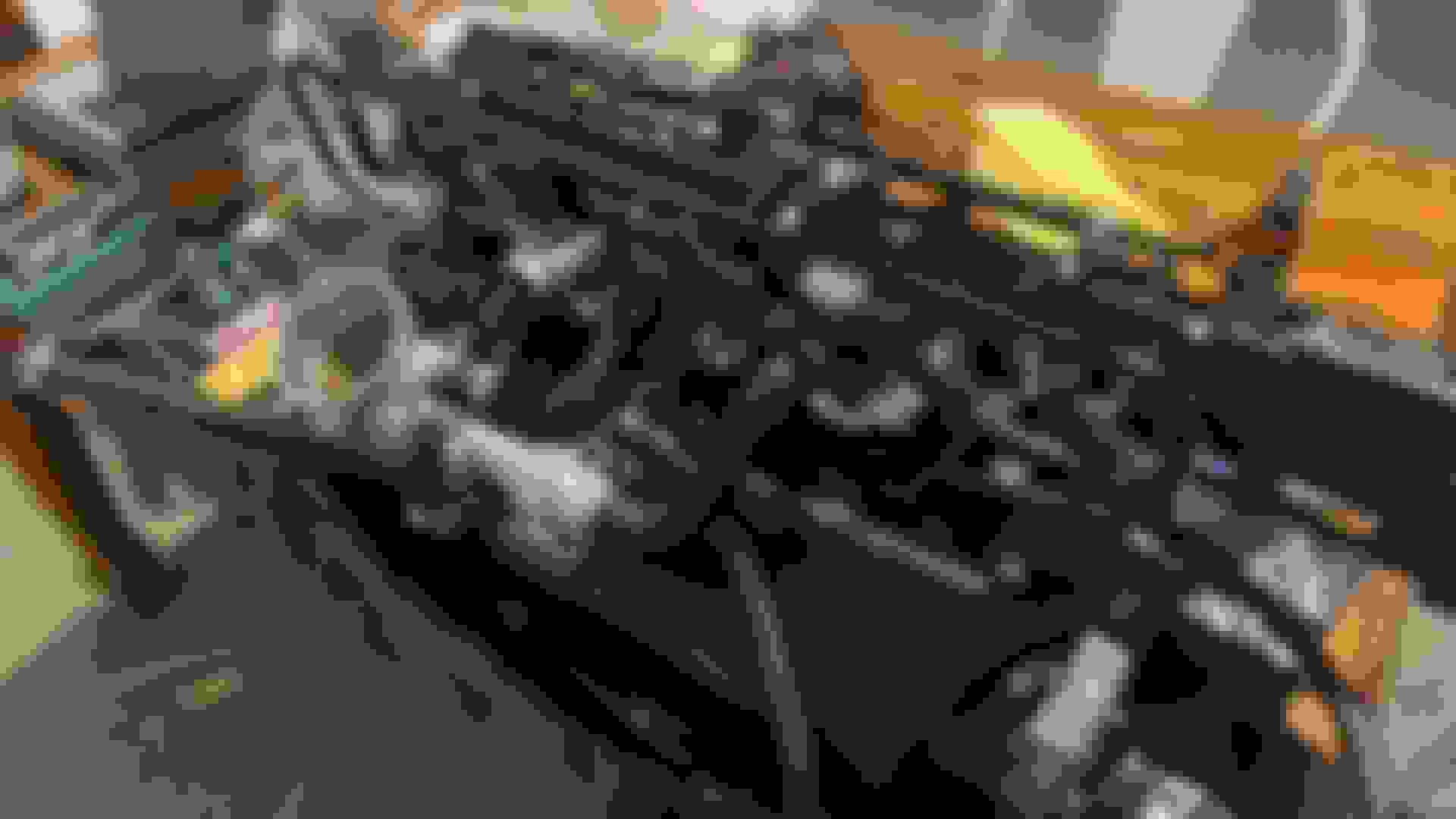
The block is well and truly ready to come out now, I just need to source an engine crane. Then it's disassemble and off to the machine shop.
Quite a big milestone for me having never done such a thing, and it went well, no damage and minimal drama.
The caveat being that the torque converter came with the flex plate, which is apparently going to be a pain to get back into the trans.
Had I known how it was mated (sans bolts), I might have been able to reach in and wiggle it off before it came out too far.
Anyhow, it was gentle wiggling that got it off, so thats out too, I guess I'll clean rust treat the surface rust and put it back in place.
Any advice on the torque converter while it's out? I don't think I can service such a thing other than clean and protect.
The pesty bit of block removal (trans staying) was the trans oil cooler pipes. Which requires you to take off the engine oil pipe from the oil filter housing. - there is an O-ring under it on the sump surface. Not a gasket.
I believe this to be the easiest way to get the block out san trans.
I still need to see how hard it is to put the pipes back on reinstallation.
For the record, I did this with the bonnet on, the head and manifolds off and the trans staying in the car.
So it came out over the fender.
Notes:
Check that you know how your crane and engine stand will interface first. Confirm that the stand can fit in the correct position to load the engine on.
Check that you have enough room to pull the crane out and move it around to allow the stand in. - I had to muck around due to minimal space, but after rehearsing it I found a method that would work.
SWEEP, you don't want to hit small stones with the wheels on the stand or the crane.
Make sure that you have enough spacers or that the "bell housing to block" bolts will be able to tighten engine to the stand. Good washers too - Or use new ones, I think I'll be throwing these ones I've used away.
Heres a rough list of the proceedings:
Support the trans.
Loosen all bolts, hook up crane, lift engine and check rigging, THEN remove bolts. - Flex plate bolts were accessed through the starter motor hole. I think you can get to them through the inspection plate on the bottom front face of the bell housing. Small bolts to take plate off.
- I used a battery rattle gun on the flex plate bolts after soaking in penetration oil, they came out well.
- The engine block shouldn't drop as long as the engine mounts are attached, The block and bell housing have dowels between them stopping vertical movement.
Unbolting engine mounts break it free - (I had to do the mounting plate rather than the rubber on one side due to interference between bolts and nuts.). So it's important that the motor is suspended at this point. - Actually, just coming back to this later, you should be able to loosen the bolt on the rubber mount, lift and then loosen more, if there is interference.
During raising of the engine, make sure to check the trans support often, as the engine will lift the trans with it until it clears. At which point the trans will drop if not supported (I think). I checked and adjusted every time I lifted the engine.
Some forward movement is required to come off the dowels and clear the flex plate, I used a small crowbar in the starter motor hole to pry it apart gently. No force was required for my engine.
It was mostly lifting of the block that got it out, which was ideal because the crane feet foul on the front wheel and didn't allow much side to side movement.
If the torque converter came with the flex plate/block, then some wiggling will get it off if the bolts are removed.
The 8 flex plate bolts came off with the small battery rattle gun (165nm impact driver).
Then a bit of wood (for protection) and a 4lb hammer to smack the flex plate where it is exposed by the starter "hole", rotate and smack, rotate and smack to get it off evenly.
Mount engine on stand.
Then I took a very exciting (not), trip with the engine on stand all the way around the house on a thin rough concrete path.
Which honestly wasn't ideal, an engine stand is not designed for shock loads, ie the engine bouncing as you pull it. So I had to support the weight in a way to stop the bouncing.
Unfortunately, I have nothing but a small garden shed, of which the door is too small to get the engine stand through (and it's not ground level), plus theres a lawn between the path and the shed to content with.
Which I don't want to take the stand across.
So, I'll be doing all work on the block outside under the very small eves of the house and covering at night. I might have to reconsider this when it comes to reassembly time.
Next steps include a bit of a clean and disassemble and inspect.
Excuse the massive rigging sling and shackles haha
An engine levelling bar would have made this easier and stopped contact between torque converter and bell housing.
This is simply more chronicling of disassembly really and I imagine at this point the content I'm writing isn't very interesting, but because I've found old posts on this forum to be so helpful when I'm stuck, I'll continue to write it up incase helpful for someone else at some time.
Progress has been, sump, timing cover and timing chains.
Sump off first, that unbuttoned easy. I wouldn't do it upside down due to the remaining oil. So I used two ratchet straps to create a sort of basket (two slings) for the sump to drop into.
The harmonic balancer then came off, I think you really need an actual harmonic balancer puller for this task, which is what I used.
So if you don't have one, a cheap one worked for me.
Note: the bolts on the balancer are in a square pattern, so you can only use two bolts with one of those funny looking Y pullers (I used one like this and it worked ok).
I would also buy some suitable bolts for this task, I used the ones from the car and I didn't like it much.
Seat the tool in the crank bolt NOT the crank shaft (thread damage).
Greg in France suggests:
Originally Posted by Greg in France
With pullers, get a bit of tension on the thig being pulled with the puller, just using a spanner, and then tap the thing being pulled lightly but sharply with a hammer to let the shockwave do the loosening. Rinse and repeat until it comes loose.
The balancer popped right off, and I mean POPPED. It flew out a good 100mm before I caught it, I was happy I did, I was in bare feet (that was silly, wear boots plz), don't worry I applied the trusty safety-squint as it popped off to protect my eyes from flying bits.
Then remove the woodruff key (half moon thingy) with a gentle screw driver hit on one side until it rotates out.
Then I thought I'd have a go at the timing cover, which will only come off directly off the front, not up and down due to dowels. (Sump must be off).
So I changed my mind and did the balancer cone first. I used a three arm puller for this. Again with the crank bolt in. Came off easy. Yay.
The timing cover came off now, I had to pry it off very carefully top the top, then a careful flat head half way down on each side till it came off.
Then the woodruff key before the "distance piece" or spacer if you want to call it that, that was penetrating oil and some wiggling to get it started and then gentle three arm puller again.
Timing chain its self comes off easy, it's just 4 bolts (upper guide ones) and it comes off as an assembly.
But first take the lower timing change tensioner off, I didn't know it was spring loaded and it popped open on removal. So maybe zip tie that closed first.
Then the entire assembly comes off once you remove the 4 bolts that hold the upper guides in place. (The spacers are loose behind them so catch them).
Alright thats enough listing of what I did, now, I do believe that this engine has had some work on the timing chain before.
I wonder this because the tensioner has a rubber pad that is glued on, rather than moulded.
My research shows that the jaguar one was moulded. The wear is consistent on all guides though, so either:
Jaguar changed to a moulded pad after 1980, or someone's done the pads and guides at some point.
Though the tensioner body is a Reynold, which apparently is the type to have. (with Rolon apparently being the brand of the devil, I think SNG sell the Rolon one cheap maybe, dunno).
Tensioner internals - small cone shaped filter hiding behind the dowel in block not shown.
See how you can see the plate the pad sits on, the jaguar ones are encased covered in rubber (but maybe that changed at some point).
The lower chain had about 8mm of play on the non tensioned side and the tensioner was sitting out maybe 8mm, I'm not sure whats normal in this case, so I will probably replace chains and the tensioner.
The gears look good.
Pad wear, doesn't look too bad to me honestly. But I'm here so I'll replace it with a Jag one.
Wear on the shaft (piston?) too. Doesn't look too bad to me but I don't have a good frame of reference.
Yeeeeeaaahhhup.
Cheers,
H
Last edited by Harry Dredge; 02-13-2024 at 10:50 PM.
This is simply more chronicling of disassembly really and I imagine at this point the content I'm writing isn't very interesting, but because I've found old posts on this forum to be so helpful when I'm stuck, I'll continue to write it up incase helpful for someone else at some time.
That's very thoughtful of you.
...Use an impact driver rather than hand tools and seat the tool in the crank bolt NOT the crank shaft (thread damage)....
Cheers,
H
I have perhaps misunderstood your process here, but I'm not a big fan of using Impact Tools on pullers (or spring compressors for that matter).
Usually the bolts included with these tools are not designed for this sort of sharp hammering (unless of course included instructions state otherwise). I've seen bolts break while doing this (wasn't me!) and then it was a Real Mess! Damage occurred and blood flowed!
Undoing bolts is a different matter, and snugging up nuts and bolts, but for pullers, the ever increasing tension delivered in Sharp Hammering blows can lead to Disaster if one of the lead screws decides its had enough and gives way.
Agreed. With pullers, get a bit of tension on the think being pulled with the puller, just using a spanner, and then tap the thing being pulled lightly but sharply with a hammer to let the shockwave do the loosening. Rinse and repeat until it comes loose.
Unless you have a splined hub/driveshaft stuck in the rear hub in which case only 40 tonne pulsing-action press will shift it!
Last edited by Greg in France; 02-13-2024 at 02:02 PM.
Enjoying your story but may I ask you to place a two foot section of wood to the front of the engine to the engine stand to help hold it up. I have seen the head of the engine stand break and drop the engine on my friends feet.
Thank you.
I have perhaps misunderstood your process here, but I'm not a big fan of using Impact Tools on pullers (or spring compressors for that matter).
Usually the bolts included with these tools are not designed for this sort of sharp hammering (unless of course included instructions state otherwise). I've seen bolts break while doing this (wasn't me!) and then it was a Real Mess! Damage occurred and blood flowed!
(';')
Haha no I don't think you have misunderstood, note taken! I'll update the post to reflect that advice.
Originally Posted by Greg in France
Agreed. With pullers, get a bit of tension on the think being pulled with the puller, just using a spanner, and then tap the thing being pulled lightly but sharply with a hammer to let the shockwave do the loosening. Rinse and repeat until it comes loose.
Noted! Thank you.
I guess I was looking for a way to get rotation without locking the crank up somehow, and the impact did it in two short bursts.
But I do agree that it's very possible that damage to engine or body could occur.
Originally Posted by Larry Louton
Enjoying your story but may I ask you to place a two foot section of wood to the front of the engine to the engine stand to help hold it up. I have seen the head of the engine stand break and drop the engine on my friends feet.
Thank you.
Ouch! Yes good advice, I was trusting that this engine stands strength would match that of its rating but I think perhaps that you are right about this.
Better to be safe than sorry. In the back of my mind I have doubted the quality of this stand more than once.
For the torque converter, it needs to be assembled onto the transmission first to ensure that the drive dogs on the end of the converter are seated properly into the pump. Then offer up the converter/transmission to the flex plate with the engine in the car and make sure that the input shaft goes into the end of the crankshaft cleanly. You don't want to bolt the converter to the flexplate and then try and offer up the transmission to the block, as if you get the angle slightly wrong it can damage the bushing inside the pump. It's easier to see if the bellhousing is square to the block and the input shaft is lined up with the bushing in the crankshaft if the converter is in the bellhousing.
Then look at the converter to flexplate spacing. It should be about 1/8" or so. More than that and you'll want to put small washers between the flexplate and the hubs on the converter, this is to ensure that the converter is well seated into the pump and the bushing that supports the input shaft/converter. You can spin the converter around once the transmission is bolted to the block and put in the converter to flexplate bolts through the access panel at the bottom of the bellhousing.
Once some friends and I were trying to reinstall an auto box by bolting the TC to the crank flange first (we didn't know any better) because the guy with the wrench, my BF at the time, didn't want to mess with reaching into that space to do what we later learned was the proper way.
Then they raised the trans, stuck the input shaft into the TC, twisted the tail shaft until it seemed to seat about right and started tightening the mounting bolts to the block. Pretty soon, after it was getting Way too tight in my opinion (but who listens to a just girl friend), there was a >tink< from the front of the trans and car didn't move upon total reassembly.
Tear down revealed the gorilla with the wench had Broken the pump drive gear by not getting it seated correctly!
His name was Mud as it wasn't his car, and he glared daggers at me for 2 weeks.
(Needless to say that was the end of that relationship)
For the torque converter, it needs to be assembled onto the transmission first to ensure that the drive dogs on the end of the converter are seated properly into the pump. Then offer up the converter/transmission to the flex plate with the engine in the car and make sure that the input shaft goes into the end of the crankshaft cleanly. You don't want to bolt the converter to the flexplate and then try and offer up the transmission to the block, as if you get the angle slightly wrong it can damage the bushing inside the pump. It's easier to see if the bellhousing is square to the block and the input shaft is lined up with the bushing in the crankshaft if the converter is in the bellhousing.
Then look at the converter to flexplate spacing. It should be about 1/8" or so. More than that and you'll want to put small washers between the flexplate and the hubs on the converter, this is to ensure that the converter is well seated into the pump and the bushing that supports the input shaft/converter. You can spin the converter around once the transmission is bolted to the block and put in the converter to flexplate bolts through the access panel at the bottom of the bellhousing.
Ok, thanks for the detailed explanation.
Tell me if I've got this wrong.
Put the convert back into the trans first, making sure that the cogs seat well, there is an outer and an inner. - Which I've been careful not to rotate, Maybe it will slip right in.
Seat that FULLY.
The small shaft on the converter must line up with the hole in the crank and seat well. - This would be the shaft that was holding the converter to the flex plate on removal.
For the 1/8" spacing, do you mean that when block is bolted to bell housing, check the gap between the converter and the flex plate?
I assume that by bolting these together the converter is pulled out slightly by 1/8", If it's more add washers. Which will keep the converter further in the trans.
However, I'm not sure how that would change much on reassembly if all parts are the same and only the crank end float adjusted to spec.
And I suppose I could also rotate the engine to align the bolt holes correct? - Which is how I did it on removal. Though that was only the block, so the converter might be easier to spin.
Originally Posted by LnrB
Once some friends and I were trying to reinstall an auto box by bolting the TC to the crank flange first (we didn't know any better) because the guy with the wrench, my BF at the time, didn't want to mess with reaching into that space to do what we later learned was the proper way.
Lucky I've got the knowledge from here to stop me falling into traps like that! haha
Much appreciated.
I got the pistons out, after a little drama not knowing what the nut size on the big end of the piston rod.
I fell into a trap because my socket set is 6 sided, on account of 6 sided apparently being better at not slipping.
So fairly much, I tried to buy a single 12 point socket to fit, got the wrong size and then eventually found out that my 1/2" ring spanner is what I needed, silly me. - 1/2 Inch 12 point socket would have been better.
No Jammed rings, they all rotate nicely I'll check with feelers etc after I check the manual.
From the manual: Side clearance of top compression ring in groove - 0.038 to 0.089 mm
Side clearance of second compression ring in groove - 0.038 to 0.089 mm
Measured between the ring and the ring land right the way around the piston.
From my basic inspection (without cleaning) they look pretty ok I think, I think they have got wear from piston slap. But I'm no expert.
Would someone let me know if this is normal wear on the skirts? I really don't want to be buying new pistons haha.
About 150,000k on the engine.
The bearings are looking pretty tired and so will be replaced, I don't think they look totally terrible though right? Nothing to worry about here?
Example of the wear on the crank - Piston big end. Looks worse in the photo and I can't feel anything with my nail.
I'll get it polished at a minimum.
I'll measure the piston bores also, but over all I think they look ok? But again first time looking at this sort of thing.
Theres one or two vertical scores that I can't feel with my nail and one bore that has a few horizontal lines from coolant leaking into that bore.
But again, I can't feel them and I think it'll just wash off.
I'm not sure if its the flash of the camera but I think I can see some wear from the supposed piston slap.
You still have factory hone marks in those cylinders! You still have hone marks even in the piston wear areas!
I have seen a Lot worse for those miles. I'd just scuff it up with a glaze breaker.
I've seen a Lot worse bearings too! Those aren't even down to the copper yet!
I'd have to feel the crank, but by the look of the bearings, I'd put it back in with minimal messing.
New rings and bearings and use it all again.
(';')
For the 1/8" spacing, do you mean that when block is bolted to bell housing, check the gap between the converter and the flex plate?
I assume that by bolting these together the converter is pulled out slightly by 1/8", If it's more add washers. Which will keep the converter further in the trans.
However, I'm not sure how that would change much on reassembly if all parts are the same and only the crank end float adjusted to spec.
Correct. When the converter is pushed all the way back into the transmission, look at the gap between the converter and the flexplate. You can use a screwdriver to lever the converter backwards ( gently) to see what the maximum gap is. It should be good, since you are using the original converter. Some Chevys were rather loose on their tolerances and sometimes the converter wasn't well seated into the pump and it can shear off the ends of the drive lugs. One transmission rebuilder I follow says that converter spacing is one thing he always has to check on every GM build he does, as it's often wrong from the factory. I have no idea how good Jaguar was. Although if the car has survived this long with no obvious damage, it's probably just fine.
The bearings have a few score marks from dirt, but if those have been in there for 150,000 km that is excellent. The bore wear and wear of pistons to me looks like the pistons were actually tight, and that is contact wear. Piston slap is usually at the bottom of the skirt. I think your skirt-bore clearance was a little small originally - either that or it was driven hard and overheated and the pistons expanded more than intended.
At this point any damage has been done, you can probably put them back after a cleaning, making sure they go back in the bore they came out of. With the factory(?) hone marks I wouldn't bother doing anything to the bore, just give them a good cleaning and make sure they are dirt free, then reassemble when the time comes.
Are they factory pistons? Or has the engine been rebuilt before? If factory, you should see a factory part number stamped on the top and probably a grade letter.
T
Are they factory pistons? Or has the engine been rebuilt before? If factory, you should see a factory part number stamped on the top and probably a grade letter.
I would wager that this engine has been apart before. I stripped my engine at 70,000miles and it was way better than this one. The hone pattern does not look like the factory one.
That said, I can see no reason not to use the pistons again once they are dressed.

 01-28-2024, 05:56 AM