When you click on links to various merchants on this site and make a purchase, this can result in this site earning a commission. Affiliate programs and affiliations include, but are not limited to, the eBay Partner Network.
What's the best way to test a mass airflow sensor on an '87?
The car isn't OBD-II, but we need to check airflow and fuel rich/lean. Not at a dealer, either -- independent shop. What's the best way to go about this (if any)?
Mine is a 86 XJ6. I suppose they may have changed to a mass airflow sensor in 87, but mine is a simple airflow flap operating a potentiometer. Mass airflow would need a hot wire or something to evaluate the mass of the air flowing past, right?
I've not seen any data on the resistance range to be expected from the airflow sensor, but I would expect that if there is a smooth change in resistance on operation it's probably good.
Mine is a 86 XJ6. I suppose they may have changed to a mass airflow sensor in 87, but mine is a simple airflow flap operating a potentiometer. Mass airflow would need a hot wire or something to evaluate the mass of the air flowing past, right?
Right. What we have on the old XJ6s is an Air Flow Meter. Not a Mass Airflow Sensor
I've not seen any data on the resistance range to be expected from the airflow sensor, but I would expect that if there is a smooth change in resistance on operation it's probably good.
I agree
Back in the day I reckon the dealers were provided with some sort of test equipment, along the lines of the EpiTest kit. These typically were plug-in test boxes with, in essence, "good" and "no good" lights. Finding this equipment today, in actual working condition, would be a real treat
Mine is a 86 XJ6. I suppose they may have changed to a mass airflow sensor in 87, but mine is a simple airflow flap operating a potentiometer. Mass airflow would need a hot wire or something to evaluate the mass of the air flowing past, right?
I've not seen any data on the resistance range to be expected from the airflow sensor, but I would expect that if there is a smooth change in resistance on operation it's probably good.
Probably what my car has as well. I tend to refer to all of them as MAS even if it isn't truly. We're just trying to make sure the mixture isn't being enriched beyond limits. The car is running pig-rich at the moment, getting about 11-13 mpg highway (when it usually gets 20-25) and the exhaust smells strongly of gas. This despite new injectors, plugs, wires, cap/rotor, etc.
There is another obscure thing: in the trunk forward right there are a a couple of pink wires and a pink-blue wire. the K wires are connected together and the KU is on another connector. These go to the most frequently not present high altitude switch. Lore is that it was determined to be unnecessary so they simply stopped installing the switch. The K wire is the signal from the airflow meter to the ECU. The two wires (one to the ECU, the other to the airflow meter) are joined at the connector to make the circuit. The altitude switch would apply the same signal to pin 12 on the ECU when the car ventures above something like 4000 ft msl.
On my car, lacking the switch, the two wires had lost the connector and were twisted together by some past owner. I didn't like the look of that so I disconnected them, cut the ends off to clean it up, then left it and forgot about it because the car was in the shop having the valves renewed or something like that. When we finally started the car again after some time it would nearly not run at all with a massively rich mixture. We spend days troubleshooting then I remembered the wires. I reconnected them and it was fixed.
If that circuit is broken, the ECU lacks a signal from the airflow meter, and assumes infinite air coming into the engine requiring as much fuel as possible.
A rare occurrence to have a technician disconnect wires without knowing what function they perform, but.........
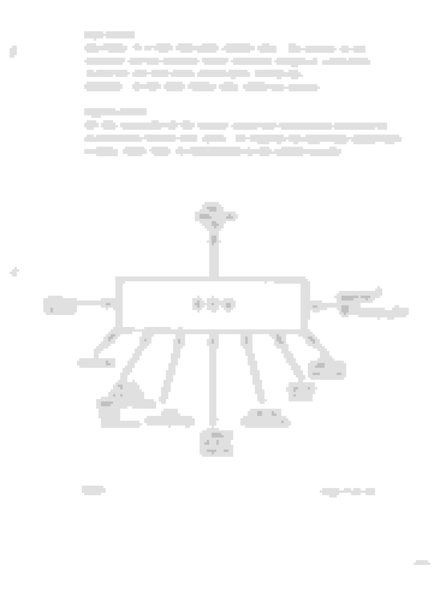
Jaguar put out a Fuel Injection Introduction that explained the components pretty well. It doesn't explain exact values, but does explain what's going on with the Air Flow Meter. I'll attach those pages.
It seems like similar over fueling issues were caused by a faulty coolant temperature sensor. That's a pretty cheap and easy thing to replace to rule that possibility out...
It seems like 20-25 mpg is a pretty lofty goal for the Series 3 though.. I think 18 is pretty well accepted.... But yeah with 11-13, something is going on...
Cheers
David
shop.EverydayXJ.com
I neglected to mention the coolant temp switch was replaced about a year ago, along with the fuel pressure regulator.
Is there a way to know what values we should be seeing from the airflow meter, coolant temp switch, etc.? We can do diagnostic work but we don't know what values we're looking for.
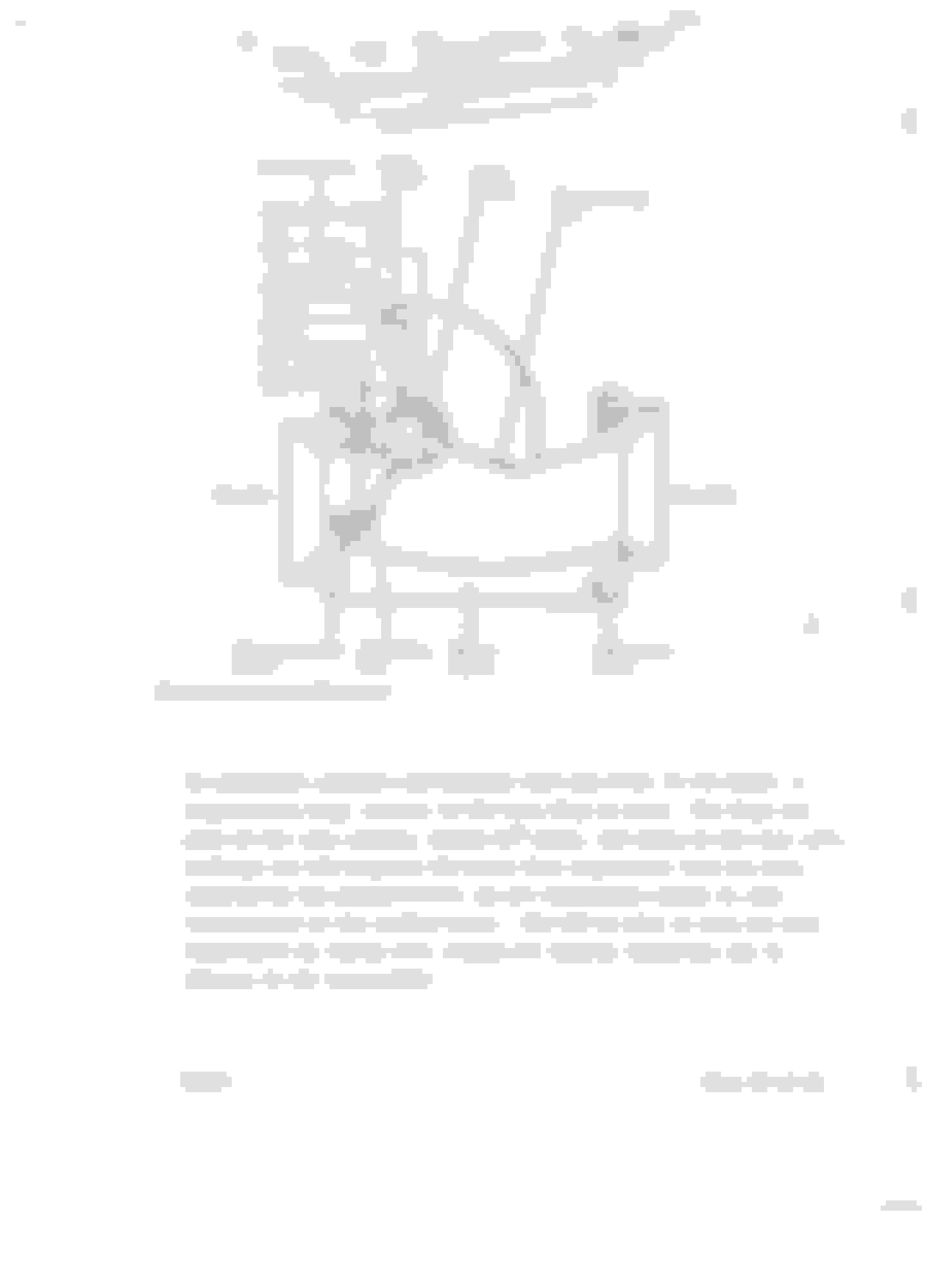
I attached ( i think) pages from the service manual that show what values to look for on the temp sensor. You'll also not that the information on the airflow meter is not presented.
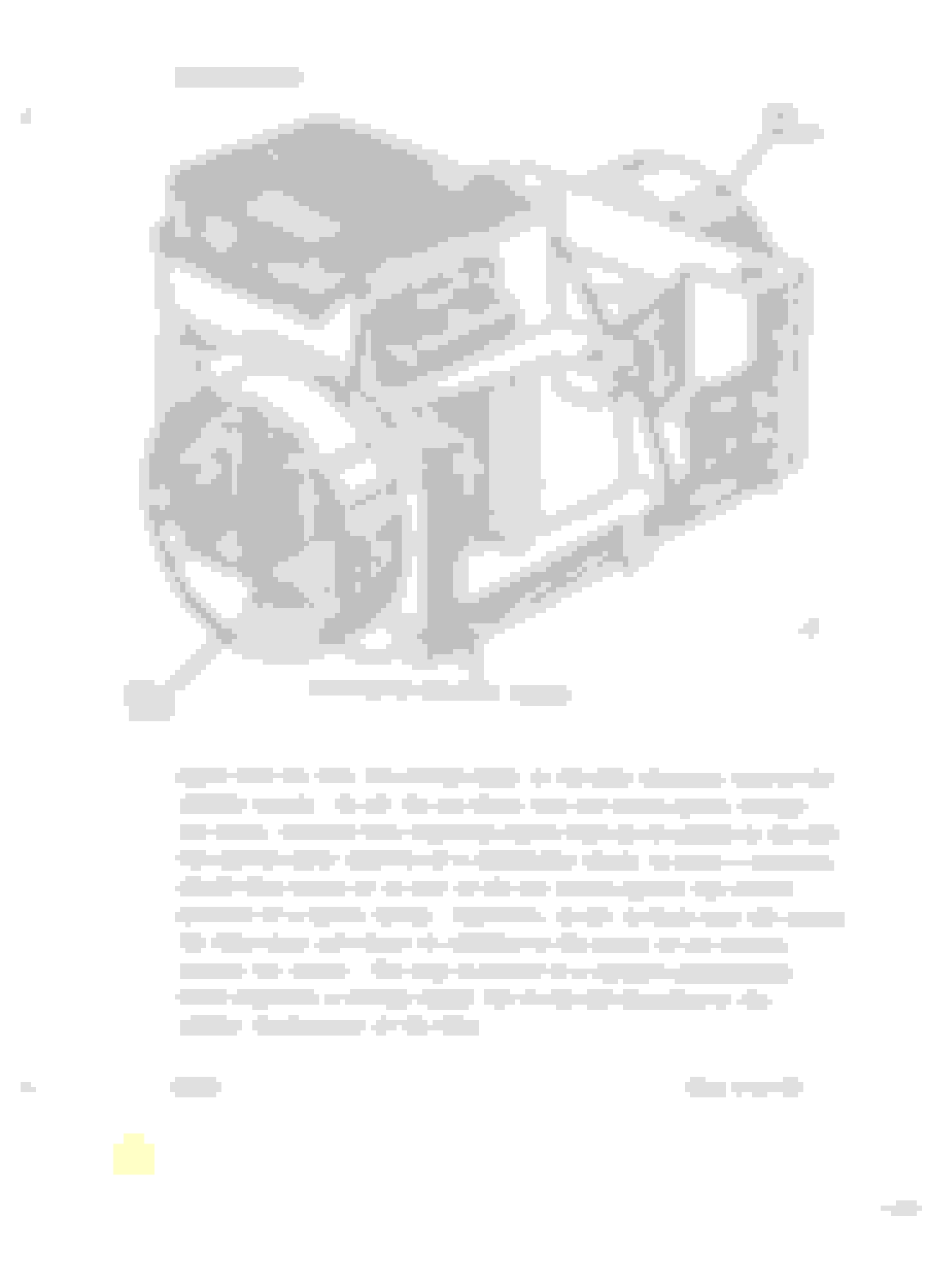
Isn't it odd that the Service Manual is talking about the Coolant Temperature sensor, but seems to show a photo of the Cold Start Injector???
Wonder if that threw anyone for a loop??
David
shop.EverydayXJ.com


 04-01-2021, 07:38 PM