When you click on links to various merchants on this site and make a purchase, this can result in this site earning a commission. Affiliate programs and affiliations include, but are not limited to, the eBay Partner Network.
I've been chipping away on the mechanical and electrical issues on my '86 XJS, and the current item on the list is getting the instrument cluster back working. I've tried cleaning the contacts, I've tried adding a supplemental ground (see Figure 1a and 1b for the locations I attached them).
Some symptoms:
- Before the transmission swap, the gauges worked quite well aside from the tach bouncing around weirdly at high RPM (>5500RPM)
- After I swapped from the TH400 to a Getrag 290, the tach occasionally would go dead and come back. There was/is also a very obnoxious rattle from the transmission tunnel cover, as I was unable to get to the mounting screws that are up behind the radio.
- Shortly thereafter, I was driving and the tachometer signal started coming through the radio, and the gauge cluster went dead. The idiot lights still work, though.
I'm wondering if I didn't either sever/chafe through an existing wire behind the radio that I haven't been able to find, or if there's another issue. I also found the instrument cluster has an electrical speedometer, not a mechanical one as I had been lead to believe it would. If anyone has any other ideas, please let me know cause I would like at least to have the fuel/oil/water gauges.
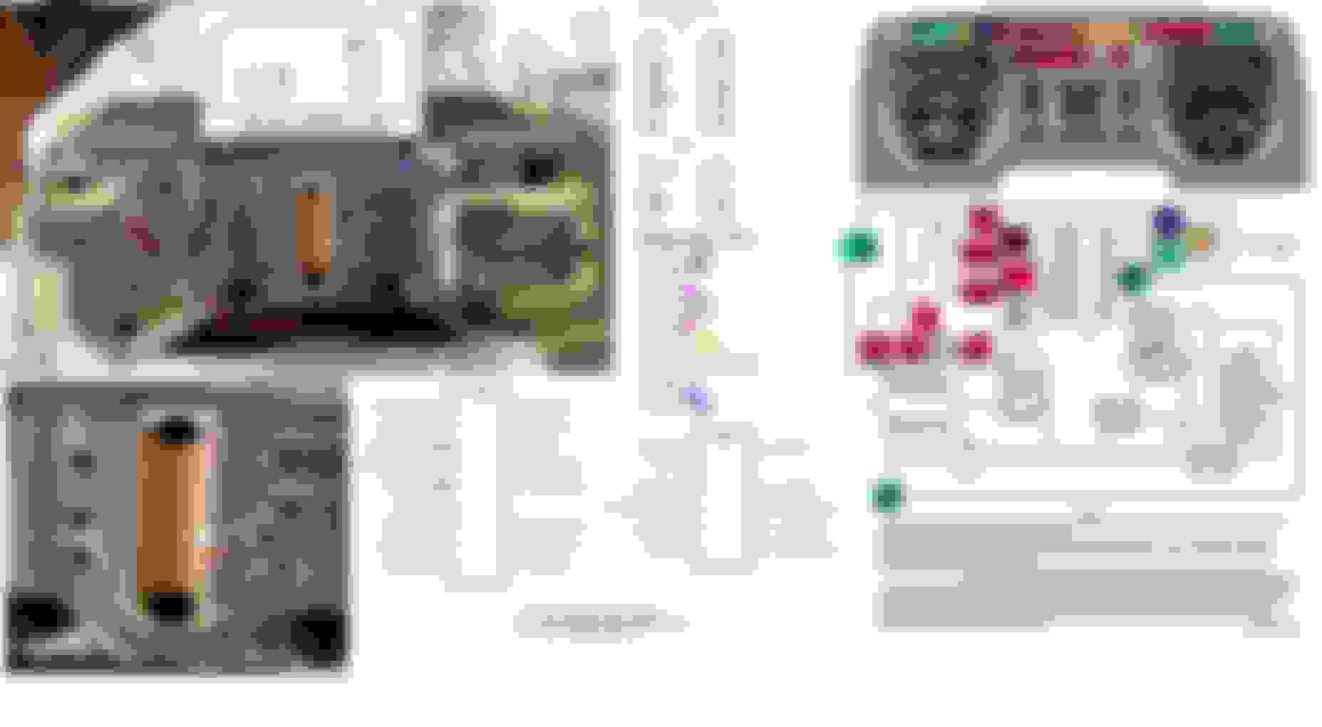
Fig 1a) Red circles indicate attempted mounting locations of auxiliary ground.
Fig 1b) needs to be made, I forgot to grab a picture of the inside of the dash. I affixed the other end of the auxiliary ground to a bolt that had a number of other ground wires affixed to it, though.
I think some of those heavily corroded screws are supposed to be conducting electricity for gauge operation. I would remove them, clean the circuit board (very carefully) and install new stainless screws.
Here's a version corrected to show the pin numbers on the harness plugs that plug into the cluster. In addition, the left left and right flasher connections were reversed.
My concern is that you've circled the nut location that I identify with the incoming Tach pulse (the lower one) - goes to J2 #5.
The corrosion on those Phillip head screws looks awful. I can say that power/signals pass through those screws into how they bite into the side of the card-slot barrel gauges. It's literally the screw threads that pass power/signal. Def a lot of cleaning with chemicals and an eraser to be done there. IF you could find brass replacment Philips screws that would be perfect (McMaster Karr?)
I almost hate to mention this because A) it might not be applicable to the problem at hand and B) my memory of exact details is a little foggy
But......
There were a least a couple variations of pre-facelift clusters with different part numbers for the circuit boards, not including the obviously different mechanical versus electric speedo versions. I think it mainly comes down to slightly different warning light configurations.
If there's any disparity as to the pin-outs, and/or confusion in diagnosis, in might be a matter of different printed circuits. More research might be needed.
Just tossing this out there.
Cheers
DD
Ferrariguy's chart does point out some of the variations in the use of warning lights, for anti-lock, washer fluid level, and battery warning. Any of these diagrams at least give a place to start.
I have been through my instrument panel and the best I could do was remove all screws and nuts and the earth bar and clean everything carefully with fine sand paper to ensure all earths and positives are good. Then check continuity between all start and end points of the copper circuit runs with a multimeter. Ohm setting. If there is a breakdown find it and either try to fix it or bypass it. Other than that that's kind of all you can do with the printed circuit then look elsewhere. Note that the main connection you circled on the earth bar needs to be placed so it loops around the bar to get connection. If it is just placed and fixed down the plastic is in the way and you won't get an earth. I did this then had to remove it and fix it. Always check continuity for assurance before putting it back in the car. Lessons learnt....
I've been chipping away on the mechanical and electrical issues on my '86 XJS, and the current item on the list is getting the instrument cluster back working. I've tried cleaning the contacts, I've tried adding a supplemental ground (see Figure 1a and 1b for the locations I attached them).
Some symptoms:
- Before the transmission swap, the gauges worked quite well aside from the tach bouncing around weirdly at high RPM (>5500RPM)
- After I swapped from the TH400 to a Getrag 290, the tach occasionally would go dead and come back. There was/is also a very obnoxious rattle from the transmission tunnel cover, as I was unable to get to the mounting screws that are up behind the radio.
- Shortly thereafter, I was driving and the tachometer signal started coming through the radio, and the gauge cluster went dead. The idiot lights still work, though.
I'm wondering if I didn't either sever/chafe through an existing wire behind the radio that I haven't been able to find, or if there's another issue. I also found the instrument cluster has an electrical speedometer, not a mechanical one as I had been lead to believe it would. If anyone has any other ideas, please let me know cause I would like at least to have the fuel/oil/water gauges.
Fig 1a) Red circles indicate attempted mounting locations of auxiliary ground.
Fig 1b) needs to be made, I forgot to grab a picture of the inside of the dash. I affixed the other end of the auxiliary ground to a bolt that had a number of other ground wires affixed to it, though.
Hey Man.
On my cluster there is a long flat straight metal bar that goes across the top back of the cluster that is a continuous ground for (memory) three ground points...
Also,,, check the fuse for the cluster... The nut that you circled is NOT a ground. It is the tach pulse. If you follow the trace it leads to pin 3 (or 5)... One of those of for the power supply to the tach,,, the other delivers the tach pulse.
 05-09-2022, 09:44 AM