When you click on links to various merchants on this site and make a purchase, this can result in this site earning a commission. Affiliate programs and affiliations include, but are not limited to, the eBay Partner Network.
I have been working on installation of a replacement 5.3 engine in my 90 XJS. Car has a 5 speed manual conversion. Engine was replaced following development of a rod knock. I will tear down the bottom end when I get ambitious. Got another engine, changed head gaskets and have been hooking everything up as time permits over the last couple months.
I sorted out earlier problems with the starter, draining old fuel and vacuum line routing and attempted to start the car today. It turned over, but would not fire. Remembering an Orangeblossom thread on a long term restoration and trouble with his fuel filter, so I disconnected the fuel line at the right side pressure regulator and with the ignition on and the fuel pump running no fuel was coming out. I swapped out the fuel filter and fuel was now coming out. Still no fire when turning over. Checked for spark, which I have, but did not hear any injectors clicking.
I want to check for power to the fuel injectors at the Feedback Monitor. I can't seem to locate it. The feedback monitor is not listed on the diagram indicating location of fuel system components. The feedback monitor is listed on the wiring diagram. Any one know where it is located? I assume it is a four pin connector in the boot (trunk)?
I have started the review of the Sticky on non-starting XJS, but don't see a discussion on injectors yet. If I am reading the wiring diagram correctly, all injectors have a Pink and Black wire (KB), which I am assuming is power? If that is true, I should be able to read positive volts at the KB wire at the Feedback Monitor, assuming I can find it.
Any other suggestions on troubleshooting injectors?
Spark Tester installed inline at spark plug 2B for ease of access. Fuel Injection wiring schematic showing Feedback Monitor EFI wiring diagram for 1990 XJS My description of ECU pins Fuel Injection Component Location Wiring diagram for injectors Wire color code
Some of the later year diagrams show feedback circuit as being the diagnostic socket. Slight variation in wire colours and pin outs but it may give you something to work with.
The diagnostic socket is to the rear right hand of engine. (at least it is on my RHD vehicle. This is where l connected my TCU for engine speed signal)
The '89 diagram labels feedback as "feedback monitor sockets" so l suspect there never was any onboard feedback monitor.
Edit. Might need to disregard what l have posted here. On further checking this is NOT the same diagnostic socket l have used. On the '92 diagram your socket is listed as being a 6 way socket below right hand a/c outlet.
I rebuilt my FI harness this year. I terminated the wires into a LH and RH set of barrier strips mounted to the RH air cleaner, near where the original FI harness plug sits.. I fitted these with LEDs so I could get real time diagnostics.
i also used silicon high temp wire and new bosch connectors.
I reviewed the "So Ya got a HE V12 that wont Start." and performed the Injector Pulse Test listed in the section EFI electrical issues. I think I hear the injectors click once.as the throttle capstan is turned. This was after cleaning the three pin plug for the TPS and the wiring harness plug it connects to with CRC Electronic Cleaner.
Still not firing. I will clean the power resister connections next at the resistor pack. I am also going to look for the connector mentioned by baxtor.
I looked under the dash on the right side and opened the fuse access panel, but did not see a connector. I finally found it in the trunk (boot) on the right side near the ECU. Four are in the red connector and the BG (black and green) is in the separate white connector,
I measured the voltage at each of the five wires with the ignition off and got:
BG = 0.4 v
Red and Green (RG) = 0.0v
Green and White (GW) = 0.6v
KB (Pink and Black) = 0.4v
B = 0.4
I measured voltage again with the ignition on and got:
Looking up at the fuse panel cover Fuel inertia switch Right side A/C vent panel fuse panel with access cover removed.
Two piece feedback monitor consisting od four pin red connector and single pin white connector
JayJagJay;
I don't think so. The wire colors indicated on the schematic for the 02 sensors are G = Green, NS = Brown and Slate, and B = Black. Other than Black for ground, those colors are not represented at the Feedback Monitor socket.
I don't know what the values measured at the socket are telling me. I pulled apart the connector for the FI harness at the right front corner of the engine bay and the female contacts look to be corroded. I tried contact cleaner, but I don't see much improvement, so I am going to clean with some sand paper and try again.
Last edited by mikebaker3; 02-04-2021 at 08:23 AM.
Reason: fix a typo
JayJagJay;
I don't think so. The wire colors indicated on the schematic for the 02 sensors are G = Green, NS = Brown and Slate, and B = Black. Other than Black for ground, those colors are not represented at the Feedback Monitor socket.
Notice the red dots... Seems like everything to do with the wiring in this outlet is to do with O2 sensors... I've been trying to figure out how and what I need to do to get a reading out of them - but that's another story.
I've heard they are not that useful BUT I think the port you are looking for can be found at the back of the engine bay, near the fire wall, tucked just behind the brake fluid reservoir. Don't hold me to that and I'm not sure what kind of reading might be taken - open close duration with the right kind of reader...maybe an osilloscope?
Mike
I think this is drifting away from the fundmentals, and I doubt the diagnostic will help you anyway. The first thing is have you checked the white wire to the ECU from the engine bay? If that is OK then:
A noid light costs almost nothing and will show if the injector loom is firing.
If it is, pull an injector, one of the front two is easiest, and see if it is spraying while you crank the engine.
If it is not, check if the fuel pump is pumping fuel to the A bank FPR (which is best removed by the way)
Check the fuel pressure
Then check if the injector is clicking as you crank the engine.
Report back what you find. I am assuming you have a good spark?
Yesterday I swapped the coolant temp sensor from the used engine with the engine that I removed due to the rod knock, which sensor I knew was good. Still no start. I know there is fuel pressure at the fuel rail, I had to disconnect the fuel line at the fuel rail to get clearance for the socket wrench to change out the coolant temp sensor. The tach moves when attempting to start, but I will check for continuity at the white wire at pin 18. I will check for the injector spraying. It will be a couple of days due to weather here not cooperating.
I found that the white wire insulation was pinched by the left side intake manifold. Apparently with the wire pinched the connection to the main harness pulled loose when the wire harness was moved, With that corrected, the car wants to fire, but still does not start. Weather permitting, I will test the fuel injection harness with the Pittsburg Noid Light bought at Harbor Freight ($34.99) and do the injector spray test tomorrow and report back.
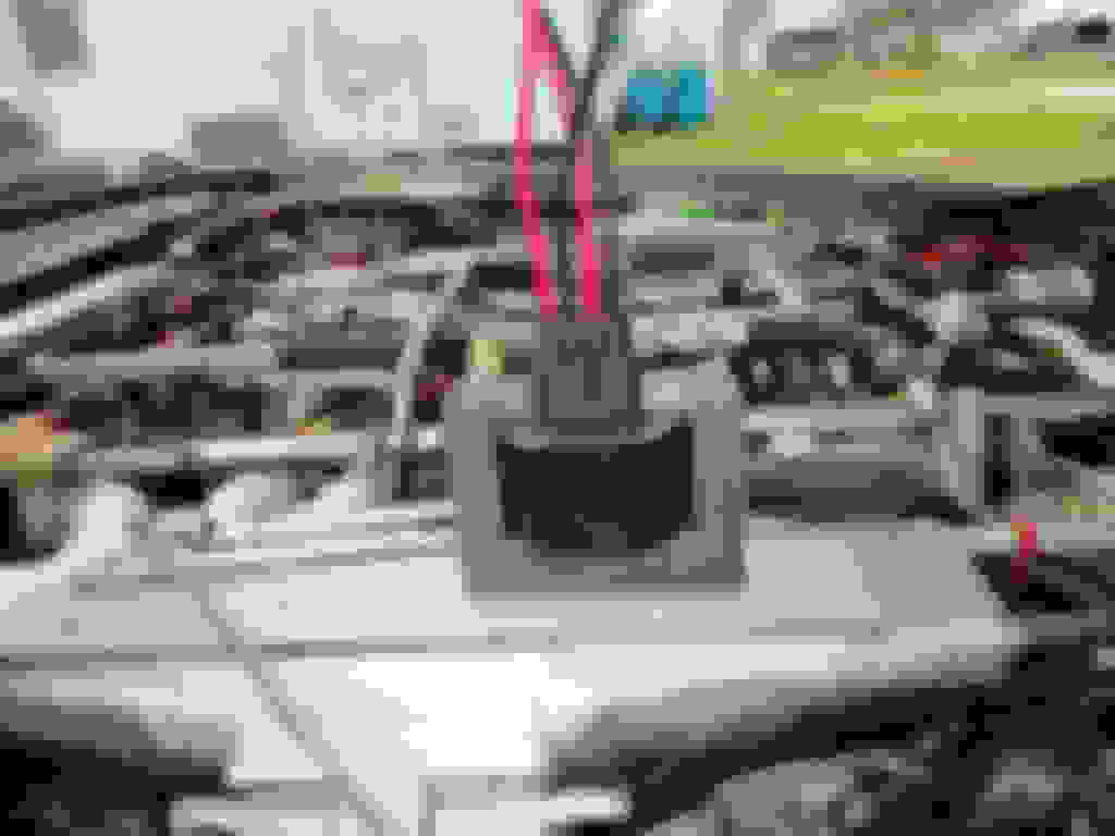
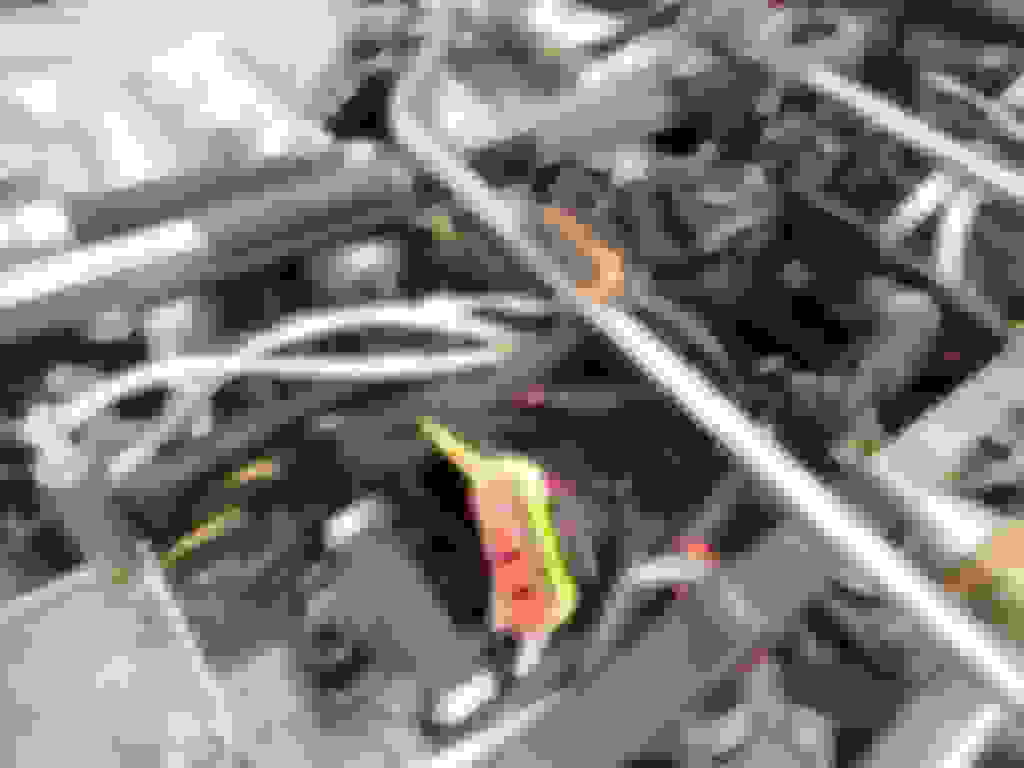
I ran a wire from pin 18 at the ECU connector to the engine bay and checked for continuity at the white wire connector in the engine valley with a multimeter and got 0.6 ohms. Noid light did not fire with engine turning over and spark tester for plug A2 indicated spark. I wanted to check white wire at coils, so I removed the throttle capstan and the top B Bank coil. I found a wire was loose at the A pin on the A coil, just inserted. I'm checking into how to remove the pin from the connector to solder the wire to the pin. All three coil electrical wires are black for pins A, B & D for both A bank and B bank coils. C pin is not used and has no wire at the connector for either coil. Not sure where the white wire originates at the engine. Pittsburg Noid Light Kit. Bosch2 light has the correct pins Fuel Injection ECU connector White wire is the pin bottom right red wire inserted into white wire pin 18 0.6 ohms measured at the wiring harness at the engine Noid light installed in 1A injector socket 0.6second view of measuring continuity of white wire from Pin 18 and the opposite end of the white wire at the engine pin numbering at coil connector weather pack connectors for both coils wire pulled loose from connector pin A of A bank coil
YETOR 16 AWG Way Car Waterproof Electrical Connector,4 pin Plug Auto Electrical Wire Connectors Marine for Car, Truck, Boat, and Other Wire Connections.(5 Pack)
I used a 1/32" blade precisian screw driver to release the A pin from the connector. While attempting to make a solder connection, the iron pushed against the pin and it proceeded to fall off and into the abyss. After looking for pin, I gave up and went to Auto Zone, coil in hand to see if I could find a replacement. I actually found a male & Female connector set for $12.95. It plugs right into the coil. It is a Dorman 91443 4 Wire Male & Female Pigtail Set. As you can see, it fits well. I went ahead and spiced the new connector into the wiring harness.
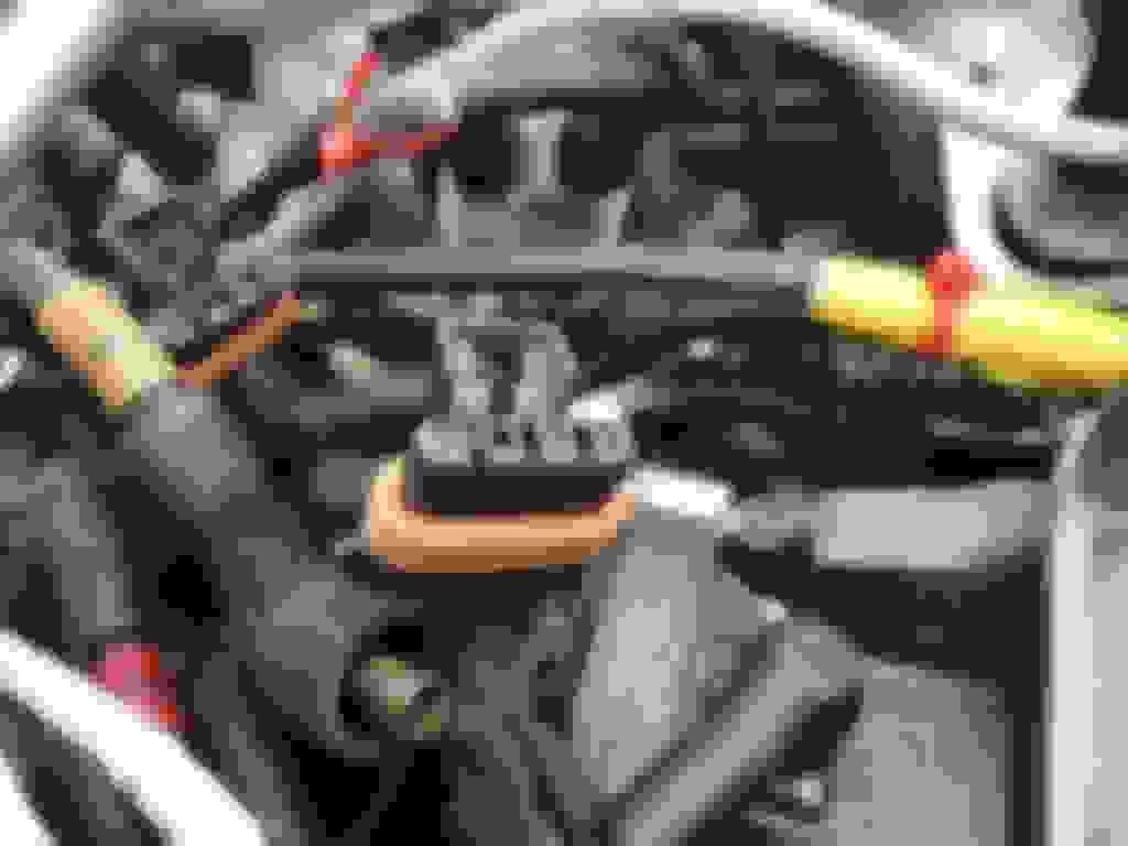
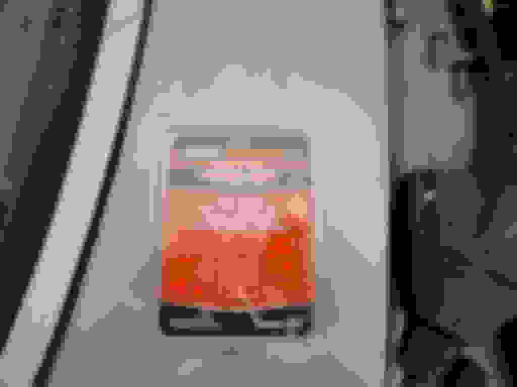
Tried the Noid test again, but still no start. I pulled the 1A injector, placed it in a jar to confirm that the Noid light did not flash. The injector did not spray. Coil connectors on Marelli Ignition Car Noid Light on 1A Injector Connector Wire that was pulled loose from connector A Bank A pin of Coil Replacement connector purchased from Auto Zone New Connector plugged into Coil to check fit. Only 3 wires are used New connector after being spliced in. Yellow seal is the new connector. Orange connector is original for B Bank. 1A injector aimed in glass jar to confirm Noid Light failure to flash is failure of injector to flash.
Mike
So did the light flash or not? Or is that the next installment?
Either way, really good work. If the injectors do not fire, a Marelli specialist on the forum will be able to tell you what to check next.
Sorry to be obscure. The Noid light did not flash. So, I guess the question is is where does the white wire for the ECU get its signal from? I will study the schematic to see where it starts. I thought about how to check for a signal. Is it a voltage, a pulse or something else I can measure?
Looking at the Digital Ignition schematic (Figure 30.1), the signal to the fuel injection ECU appears to originate at pin 24 of the Digital Ignition ECU. I will never understand engineers. Why route the wire to the engine just to then route the white wire back to the trunk and the fuel injection ECU? Tach does not move when engine turns over. I was expecting at least a bounce. There is also supposed to be a diagnostic socket with four wires, Not sure where it is located. The schematic says that the EFI wire continues on Figure 25.2. My electrical guide does not have a 25.2, but lists the EFI on 25.1. Typo on the schematic? 1990 Digital Ignition Schematic
Looking at the Digital Ignition schematic (Figure 30.1), the signal to the fuel injection ECU appears to originate at pin 24 of the Digital Ignition ECU. I will never understand engineers. Why route the wire to the engine just to then route the white wire back to the trunk and the fuel injection ECU? Tach does not move when engine turns over. I was expecting at least a bounce. There is also supposed to be a diagnostic socket with four wires, Not sure where it is located. The schematic says that the EFI wire continues on Figure 25.2. My electrical guide does not have a 25.2, but lists the EFI on 25.1. Typo on the schematic? 1990 Digital Ignition Schematic
Ok. I'm going to give this a shot. Please bare with me as I am not the BEST at this and am not one of the experts Greg mentioned above.
The image above pertains to the ignition, or spark, system. It is vital that both sensors crank and fly wheel are working and sending a good signal to the ignition ECU. The ECU (via shielded white wire) then shares this info with the ECU in the boot to time injector pulse - pin 24...
I think, just for focus on ignition, you must test alllll white ignition feed wires to the coils A and B. Then, the ignition modules A and B. And to the ECU itself... The "PINCHED" shielded white wire that that you found which goes back and provides signal (considering all ignition system is functioning) might be best handled separate for now...
I would forget the "diagnostic socket" for now.
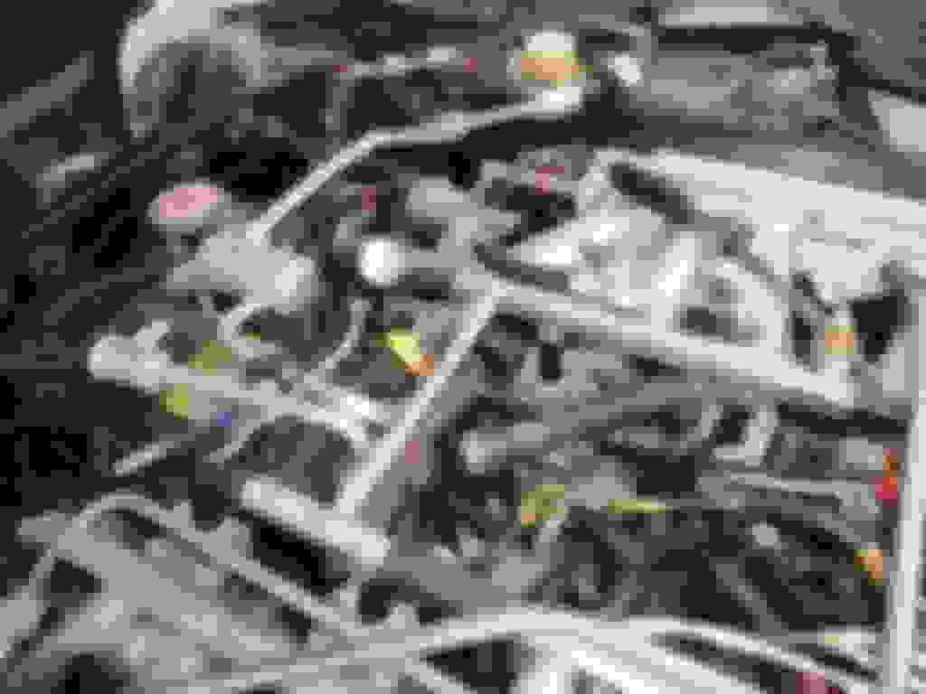
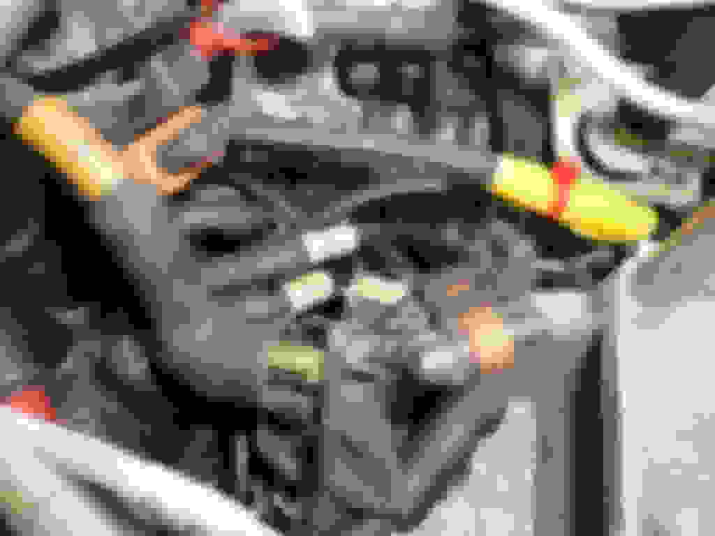
Notice the large shared connection of ignition feed wires. 5 or 6 wires in the upper LH corner of the diagram. The white wires. Yes, it actually looks like that. MUST be a strong and steady 12V... On the LH wire harness, near the fuel rail, you will find a covered section of harness that houses the power feeds for the coils, the ignition amps and a power feed that runs to the ECU (I believe)... On mine it was a very messy set up that needed to be unwrapped and redone. Considering what you found, the broken wire on the coil plug (and those wires are not supposed to be all black but striped white and black and white and brown) someone was in there before you. You need to open it all up (I know it's scary) have a look at all of that wiring. Then, if all is ok, rewrap and move on.
Check all grounds. Up at the rad (both sides) and at the fire wall.
Mike
Be 100% sure you understand exactly what the system is meant to be doing before doing anything more, I am NOT saying JJJ's advice is wrong; but rather use that as part of a structured approach along the system's intended working path. No injector pulse can then be tracked back through the system one stage at a time.
I cannot help you with Marelli, only knowing a bit about the Lucas system. Someone on the forum with top Marelli knowledge will help soon, I have no doubt.
One question though: the Marelli relies on TWO crank position sensors, one at the front and one at the flywheel. If either if these are duff the car will not start, but I do not know whether that means no injector pulse. Have you renews either of these, as if not, I would, in any event, as they do not last for ever. A forum search on Marelli CPS might help. You ARE narrowing it down, and it will be a quick fix once you understand the system - if that is any comfort!
 02-01-2021, 08:28 PM