When you click on links to various merchants on this site and make a purchase, this can result in this site earning a commission. Affiliate programs and affiliations include, but are not limited to, the eBay Partner Network.
Mike
Be 100% sure you understand exactly what the system is meant to be doing before doing anything more, I am NOT saying JJJ's advice is wrong; but rather use that as part of a structured approach along the system's intended working path. No injector pulse can then be tracked back through the system one stage at a time.
I cannot help you with Marelli, only knowing a bit about the Lucas system. Someone on the forum with top Marelli knowledge will help soon, I have no doubt.
One question though: the Marelli relies on TWO crank position sensors, one at the front and one at the flywheel. If either if these are duff the car will not start, but I do not know whether that means no injector pulse. Have you renews either of these, as if not, I would, in any event, as they do not last for ever. A forum search on Marelli CPS might help. You ARE narrowing it down, and it will be a quick fix once you understand the system - if that is any comfort!
I have to admit, me not knowing 100% is true. I think that my general understanding might be in the right-ish ball park and then, my limited understanding is further hampered by my inability to explain what I THINK I know, properly. I have to admit that. Please keep that truth in mind. I'm sorry, just trying to help.
A couple of months ago I was stuck with a car that was quickly headed to not running and I fixed my problem by digging into the combination of wiring involving the coils, the the ignition amps over the rad - where they all meet in that BUNCH of white 12v ignition feed wires that come together - in the diagram. That 5 or 6 wire 12v ignition feed loom (not as clear as it might be in the EDiagram) is also shared (wrapped together) with the wiring for the crank position sensor up front, the CTS and the signal wires going to the coils from the ignition amps... A lot going on in there.
I need to mention this as well. Check the tabs on the INSIDE of the coil housing plugs. It is very possible when pushing the plugs into the coils that the male spade ends inside of the coil will lean off to one side and never make it into the female slotted end of the plug. Ask me how I know.
Again, just trying to help.
Maybe I should hush and read on as y'all work it out...
I ran a wire from Pin 24 of the Digital Ignition ECU back to the area of the white wire under the hood (BONNET) and confirmed connection reading 0.4 ohms. I also checked voltage at the ignition feed white wire at pin 13 and got battery volts. Note the red plastic vacuum line from the rear of the R/H intake Manifold to the Ignition Module.
The digital Ignition ECU on L/H Drive Cars is in the R/H footwell. Panel is secured by two 8mm nuts and two Phillips head screws.
Looking at the Digital Ignition schematic (Figure 30.1), the signal to the fuel injection ECU appears to originate at pin 24 of the Digital Ignition ECU. I will never understand engineers. Why route the wire to the engine just to then route the white wire back to the trunk and the fuel injection ECU? Tach does not move when engine turns over. I was expecting at least a bounce. There is also supposed to be a diagnostic socket with four wires, Not sure where it is located. The schematic says that the EFI wire continues on Figure 25.2. My electrical guide does not have a 25.2, but lists the EFI on 25.1. Typo on the schematic? 1990 Digital Ignition Schematic
You're being too hard on the engineers l think.
That wire used to run from engine (amplifier) to ECU in the rear on the Lucas ignition cars and when marelli came along a compromise harness arrangment seems to have been used in order to avoid a major redo/replacement of existing harnesses.
Jaguar did not have unlimited resources at the time, if ever.
Is there a replacement firewall forward wiring harness available?
The front magnetic pickup is new. I put a new one on the engine before installing. Over the last 20 years that I have had this car, the most common ignition failure that I had was the front pickup. Car would abruptly shut off and not restart until it sat 20 minutes or so. I no nonger use the clips to secure the pickup cable at the front so that it is easier to change on the side of the road. The rear pickup counts teeth on the flywheel during engine start. Because it runs so close to the left catalytic converter the cable gets brittle. It was stiff when I set up the engine. I keep a few new pickups as spares so, I will replace the rear and see if it starts. I will tie a string to the cable at the top end and pull the cable down from the bottom and then use the sring to pull up the cable from the top and report back before I try to tackle the wiring harness.
2 8mm bolts at the flywheel. Changed the sensor. Still no start. So, I will pull the fuel rail to get access and look at the wiring harness. Harness is 31 years old, so JayJagJay may be right about the wires being crispy and brittle. Fig 1.1 of the 1990 Electrical Guide shows the Harness Layout and Connector locations. CF1 is right front, presumably up under the dash, CF6 is a connector center rear of the engine bay, so the harness should be something that can be unplugged and replaced. I will also look at the A and B bank coils to make sure no pins are bent.
Heavy rain to start in about 2 hours followed by cold weather through the weekend. I will report back next week with what I found.
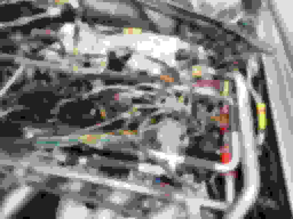
I initially thought that I would have to remove the fuel rail for access, but patience and use of some colorful language prevailed. I did remove the PVC hardline (Y line) and the connectors for the fuel injectors and the throttle turntable, but the harness came loose. I did check the pins for the A Bank coil as suggested by JayJagJay, but all pins appeared OK. It took me a while to unwrap the harness. The wrappings for about a foot in the area where the harness is near the distributor were brittle and the wire insulation was crumbling and falling off. No doubt that some shorts were taking place. I bought some shrink tubing in various A Bank Coil Pins. Look down deep Engine Harness Identification Tag
colors that I could find and will repair the harness.
The Engine Harness that connects to a plug at the same location as the Oil pressure transmitter is P/N DAC 5895 according to the tag. The other harness, based on an online inquiry, for the Marelli Ignition is DAC 6796. I looked to see if one was available. Jagbits can order one for $2,000, but that is just too much. That was the only listing that I found. I will report back with some photos when the harness is repaired.
That last photo, with all the wires, was my problem area - not looking much better than yours. After replacing wires and righting that 5 or 6 wire junction I was left with a noticable stronger run and start.
I notice that you still have the air blower system in the neighborhood of the top end? Thanks to the advise of folks here I removed mine completely in the first days of working on Cherry Pie and pulled the wiring for the injectors from the floor of the V while I was at it... Mad working on things MUCH easier... I wish I had done more, had done what you are doing here, with this wiring, in the first days. I still have a ways to go with the wiring in this area and am looking forward to some warmer days.
With the bad connections, freyed wires and the resistance and heat that builds as the wires oxidize and short, it's just a chain reaction and all the wires around the offending bad connections begin to suffer the same fate. Add the engine heat and its real trouble.
The replacement engine had a fuel injection harness that looked to be almost new.
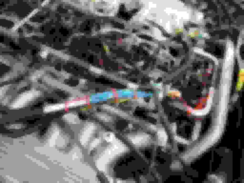
To address the crispy wires, I cut one at a time, slid heat shrink tubing over the bare wire, used a bare crimp connector that I then soldered to ensure good connection, then covered the connector with another short section of shrink tubing. Only about a 14" section of the wiring where the harness passed next to the distributor had the heat damage. The photo shows the harness after the wires were repaired, but before I wrapped the harness. There is a heat reflecting sleeve that fastens with Velcro that I plan to order and install over the harness as it lays in the Vee.. South Louisiana is having a cold spell with the temp just above freezing. I will be a few days before I get everything reconnected and can see if the problem is cured, I will report back.
Not much further along. I ended up unwrapping the rest of the digital ignition harness and found more of the same failed insulation. I have repaired it again with heat shrink for each individual wire. I still don't get a noid light. I had used the fuel injection harness that was on the replacement engine because it looked much better than my original harness, Sadly as Brake buster suggests, there is no guaranty that the harness is not deteriorated under the nice white fabric covering. I will replace the harness with the one from my original engine after checking it out to see if it is intact. and report back.
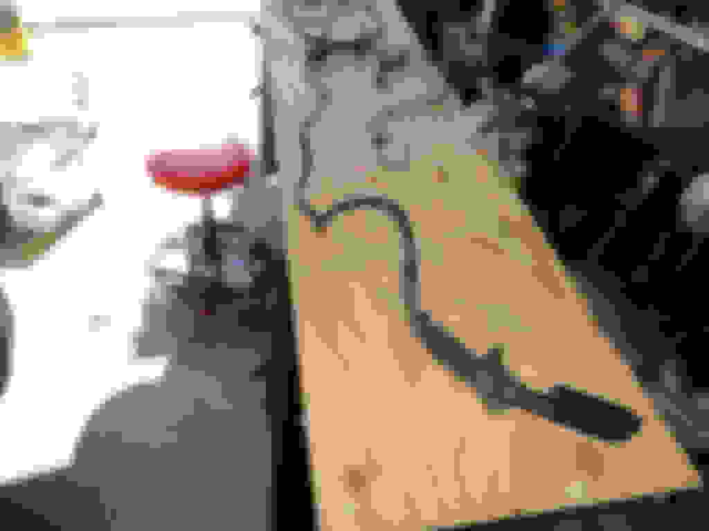
I received new wire and new terminals. Crimp tool and terminal removal tool has not arrived yet, but I went ahead and removed the ignition wire harness and laid it out on a board for inspection. The first important find was the terminals for the AMP connector that connects to the rear crank sensor had been pushed back in the housing as if the lock pins on the two terminals did not stick out enough to lock the terminals in the housing. So, I don't think the Ignition ECU was receiving the signal.
The wires leading to the 6.8K resistor providing the signal to the tach are likely shorted due to crumbled insulation. Harness layed out to unwrap and inspect Notice the crumbled insulation on wires leading to and from this resister New terminals compared to pigtail wire
Great stuff! Looks like you've found your problem(s) and are on your way. Good hunting!
Lengths on coil wires on rebuilding can be a little trick as can lengths (because of the curve over the rad and such can be too. Can get frustrating. From experience, jus take your time with it and all will be nice. One wire that ends up TOO short, creates a strange "bow" in the harness that will somehow need to be compensated for some how somewhere. Hard to explain. Haha, you'll see
I'd love to know about part numbers and such with those connectors. Makes me want to go and remove my whole set up even though I did some cleaning up already.
I know dealers have to stay in business but the prices they are charging for things is a little out of control!
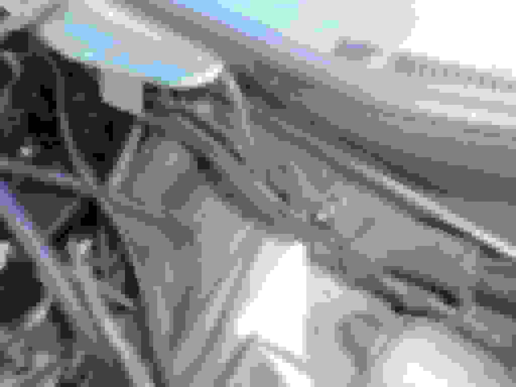
I finished the harness rebuild and have installed it. I also wrapped the harness with Cool It Thermo Sleeve to keep the heat from damaging the repaired harness. Car seems to fire and has fuel in the rail, but no Noid Light flash at 1A. I'm going to check the timing. Connectors used for crankshaft and flywheel sensors. Ground stud for ignition harness Velcro thermo sleeve from Cool it used to protect the harness from heat.
The Bosch connectors with the easy release were ordered from THMotorsports.com. Part number is in the photo above
The crimp on terminals were ordered from Newark.com stock number 52R4315 manufacturer p/n 927846-2. I bought 100 and with shipping and tax, each terminal cost $0.394
Terminal removal tool to release the terminals from the housings was bought from connectorsfast.com.
I bought a 3 in one ratcheting crimp tool for attaching the terminals, but I was never able to get the smooth looking crimps seen in the original terminal crimps.
I finished the harness rebuild and have installed it. I also wrapped the harness with Cool It Thermo Sleeve to keep the heat from damaging the repaired harness. Car seems to fire and has fuel in the rail, but no Noid Light flash at 1A. I'm going to check the timing. Connectors used for crankshaft and flywheel sensors. Ground stud for ignition harness Velcro thermo sleeve from Cool it used to protect the harness from heat.
Hey Man, Good Morning...
Hmm. This might not be what you want to hear right now,,, and it may be tough to go back - I'll just say, if and where possible, I will begin by doing the least on completely installing and wrapping a set up like this BEFORE I know that it's "working". Meaning I will kinda leave things accessable where possible and in the crudest state possible - plug everything up and in, test (all the way to full start and run) and if that works, pull everything out again, carefully wrap it, test it again, then go for the final placement.
I say all that to say that it may be possible you have a bad or faulty connection somewhere in the electrical jumble and will now have a tough time figuring it out or getting back to it.
From a voltage stand point are you getting 12+volts at that multi connection point shared by Ign Amps, Coils and to pin 13 on the ECU itself on the LH of the rail area? Are all components that should be getting voltage with key turn getting 12v?
Take a battery charger if you have one while testing and hook it up, and without starting the car but key in run position and do tests.
I guess I would make sure of VOLTAGE first THEN work to see if, from there, you at least have continuity between (sticking strictly with ignition stuff for now and not the shielded wire to the EFI ECU) all points - coils, Ign Amps, CTS - and such... Go blow by blow using the diagram for the Sign system... The problem has to be there.
The idle switch or air temp switch, I don't think you need to worry about that right now... Spark should spark without them
Is the tach needle doing the DANCE when you turn it over?
Did you say that you replaced and have known good crank sensors?
These things make me crazy and I am not the best at this but usually, almost always, my problem is right within reach.
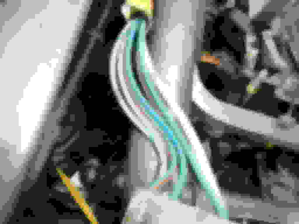
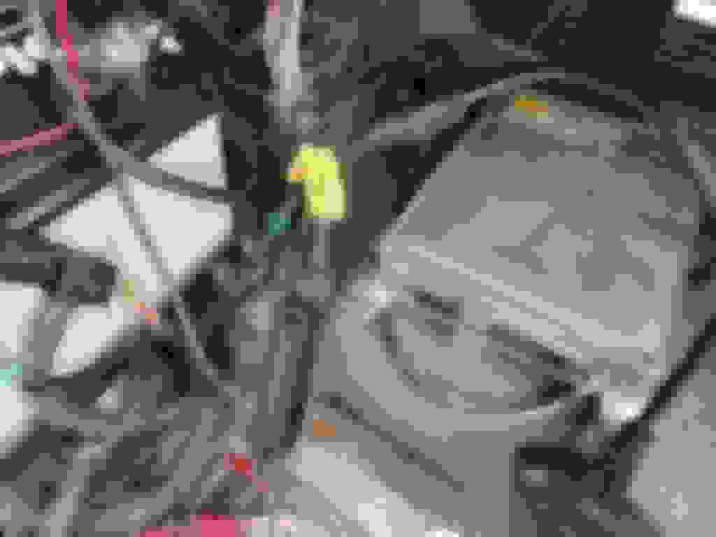
I started checking all wires between the ignition harness that connect to the Main Harness DAC 5592 connecting to the Fuel injection ECU in the trunk. I was having trouble accessing the release clip for the connector and decided to pull the ECU for access, What I found was that at some point at least one wire chaffed through the insulation and shorted out. That wire is broken and several others show melted insulation. There is green corrosion on the broken wire suggesting this was not recent. I checked online for a replacement. I did not find one. Next is to pull that harness and do a complete inspection and rebuild.
This will take me a while, so it will be a while before I post an update. The harness routes over the right rear wheel well, then to the center console and then I am not sure. Photos as I progress.
It's hard to tell by the photos,,, and what's even more the question is what caused that? Do you think and are you convinced it is all about the one chaffed wire? If so, you might not be in the worst-est spot. I haven't heard from Warren in a while - a forum member - he has a lot of electrical knowledge...
Call me crazy, but I would be thinking this. I can be a little lazy and cut corners more than many of the other fine chaps here - I should say that...
There are a lot of great products which makes it so you can pretty easily ONE BY ONE snip out the damaged or questionable sections of wire. Solder them or use a product that will self solder with heat, then heat shrink each splice.
How many do you really think you would be looking at repairing at the end of the day? 7, 8, 9, 14 individual wires in that bundle??? Might be worth thinking about. Rewiring the whole thing sounds daunting to me - and expensive...
Mike
The harness goes from the ECU in the boot as you describe, all the way to the RHS passenger footwell and through a grommet into the engine bay, without a break or connector. It is quite a big job to get it out and maybe not necessary.
If you have found the section with the problem, and you can see it seems OK each side of the bad section, then a very steady, one wire at a time, stitched in repair should do it. I think well worth trying first. Good luck.
 02-09-2021, 12:21 PM