When you click on links to various merchants on this site and make a purchase, this can result in this site earning a commission. Affiliate programs and affiliations include, but are not limited to, the eBay Partner Network.
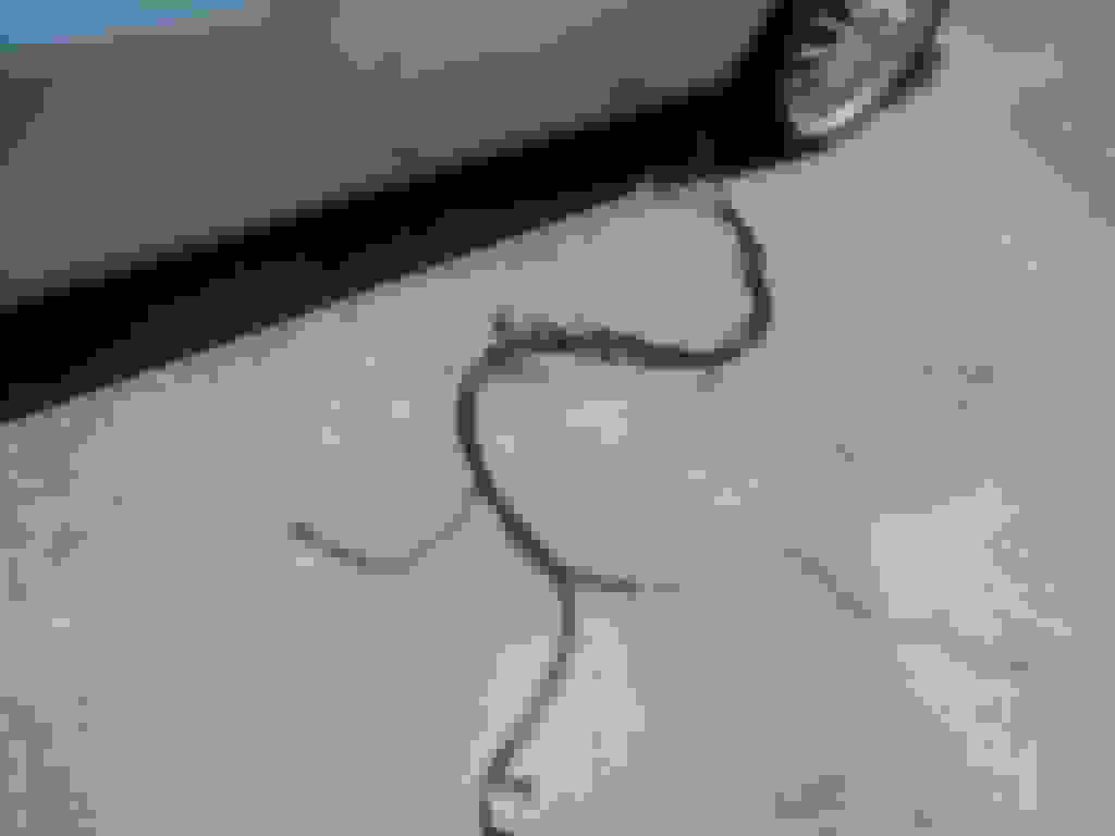
looking at the picture, it seems the broken wire has got very hot, given the 'pink ' colour to the copper that is exposed, and that the rest has gone green with corrosion , the surrounding wires have also suffered from the induced heat from this wire
this suggests to me that the wire has been exposed to unrestricted power loss to ground ( shorted out ) and from experience i would suggest this could be the whole length of the wire in that loom ??
unless you can identify the actual short to ground then the only real remedy is full length replacement as you surmised yourself
Mike
The harness goes from the ECU in the boot as you describe, all the way to the RHS passenger footwell and through a grommet into the engine bay, without a break or connector. It is quite a big job to get it out and maybe not necessary.
If you have found the section with the problem, and you can see it seems OK each side of the bad section, then a very steady, one wire at a time, stitched in repair should do it. I think well worth trying first. Good luck.
I agree.
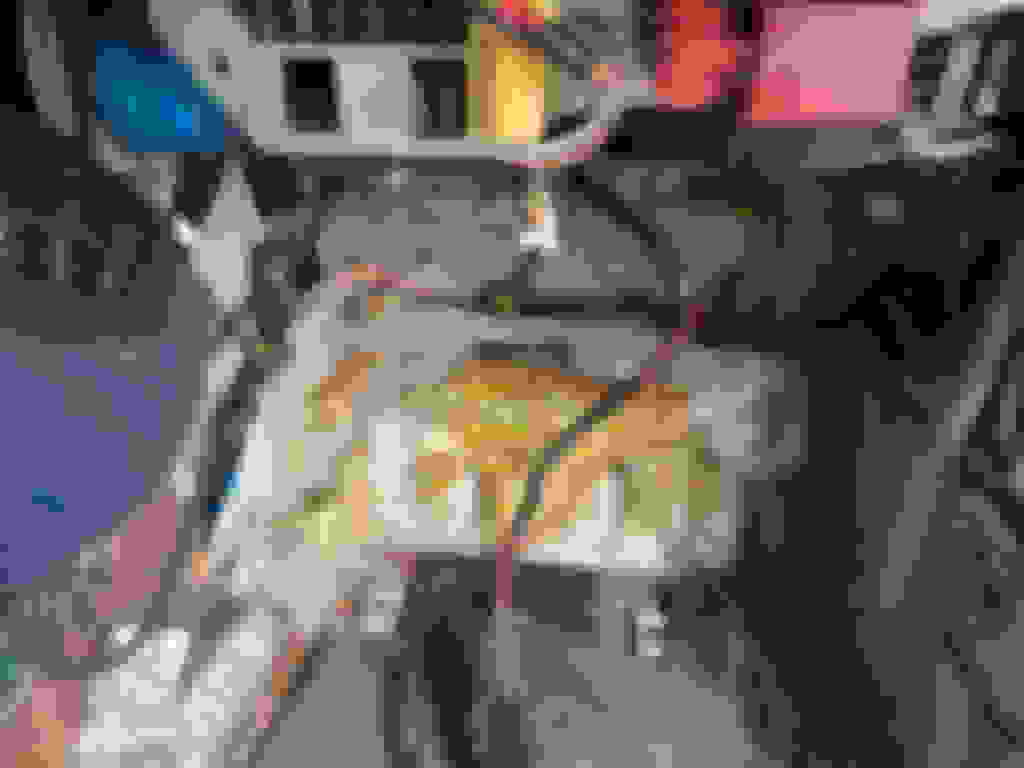
If anyone is interested I've attached a pic showing a full V12 ECU harness ready to install in the car. Removal-reinstallation is pretty invasive.
I pulled the main harness DAC 5592. The same melted wire was broken in two other places. The insulation was gone from that wire for most of the harness length. In several places, it had fused five adjoining wires together. This was apparently going on for a while. I pulled the harness through the triangular grommet just below the starter relay after removing the right wheel well splash guard and then routed the harness through the inner wheel well and into the right front foot well. The harness routes left across the front of the foot well and then aft along the right side of the console then right in front of the seat pan sandwiched in the space between the storage box that replaced the rear seat pan then under the right quarter window regulator and motor, then over the right rear wheel well to the ECU and fuel pump.
I had to remove the rear quarter window regulator and motor to gain access. to feed the harness over the rear wheel well because there is a square grommet that the main harness and the wiring harness for the rear lights both pass through.
I was extremely fortunate to locate a used DAC 5592 harness purchased from David Boger of Everyday XJ for $150. The replacement harness had a round grommet where the harness passes through the right footwell into the space between the right front inner and outer fenders. This grommet was missing and I think that it was here that the harness chaffed against the sharp edge of the metal and shorted out.
The wire Harness after removal from the engine bay before snaking into the right footwell. Triangular hole below the starter relay with rubber grommet removed Sound deadening removed from front of footwell rotated 180 degrees so that the part number can be seen. Wiring harness routed from inner fender wall across the firewall and down to run along the edge of the console. The used harness purchased had this grommet that was missing on the original. The grommet fits where the harness passes from the foot well into the space between the inner fender well. I believe that the wiring harness chaffed through from rubbing against the hole in the inner fender well because the grommet was missing. At some point in the car's history, the right front fender was replaced. Not sure why the grommet was missing. Wiring harness routed along the right side of the center console. Right rear quarter window regulator and motor that was removed to gain access to route the harness ro remove the harness into the trunk. This photo shows the main harness, the electrical harness for the power antenna and rear lights and the vacuum hose for the ECU where each passes through a square grommet as the harnesses pass from the area of the right rear quarter window and then over the right rear wheel well. This is where the harness passed from the right front footwell into the space between the inner and outer right front fender. Because this grommet was missing, I think the harness chaffed through the insulation on the burned wire, shorting out.
This shows the harness where it enters the engine bay with the triangular grommet reinstalled and before reattaching the starter relay bracket.
The wire goes to pin 24 of the ECU which the schematic says is O2 Sensor B Bank (assuming I am counting correctly). I checked it at the broken wire less than 6" from the connector. But it is not a green wire, but a black wire based upon the few sections of the wire that still have insullation. There is a black ground connecting both sensors and sensor shields to ground and to pin 23. I am going to look at the main connector at the ECU to see if it splits apart so that I can look at the wires inside.
I have not started it yet. I had pulled the battery tray to address corrosion and just reinstalled it this morning. Having rain in south Louisiana, so it will be tomorrow.
Yeah Man,,, take your time...
And thanks for reporting back.
About both questions,,, I was just wondering...
I tried to start the car today, but encountered another problem. Before installing the replacement used main harness, I had checked each pin of the ECU connector to the end of the wire and did not encounter a problem.
Without the key in the ignition, the fuel pump is running. I pulled the Main Relay, but the pump was still running and I pulled the Red Stripe Pump Relay and still had a running pump. I disconnected the brown and slate wire from the pump, which shut off the pump
So the circuit is getting power from somewhere. More to come.
Here is what I found. The fried wire in the original harness now makes sense.
If you look at the schematic earlier in this thread, There are two brown and slate wires connected to pin 87 of the Pump Relay. One runs directly to the fuel pump. The other brown and slate wire goes to O2 sensors for A & B bank (one of the two wires for the black Bosch connectors. I disconnected the connector for the left side, pump still ran. When I disconnected the right side, the pump stopped. The other wire for the connector is a black ground wire, just like the one with the insullation melted. Since that wire connected pin 23 of the ECU to ground, I am not clear on why that section melted.
Appears to me that the A-Bank O2 sensor is defective. I am going to replace both. More to come.
New O2 sensors arrived last night. I did a sisde by side comparrison measuring ohms across the two wires in each rectangular connector and also the single wire. New and old sensors read the same (zero ohms direct connection and infinity measuring the single wire to both wires of the rectangular connectors). So, ruling out the actual sensors.
I connected the rectangular connector of the r/h sensor (A bank) to the harness and checked the fuel pump with the stethescope and it is running again, with neither pump relay or the Main Relay installed. Disconnected the O2 sensor again and the fuel pump stopped.
So I am back where I started.
According to the schematic, both Main Relay and Pump Relay get power from two of the brown wires that connect directly to the battery.
I am going to look next at the two relay connectors to rule out a short there. But I don't get why the replacement harness would have the same issue as the harness that I removed.
So, what am I overlooking here? The direct battery feed for the Main relay and the Pump Relay are the two seen at the right of the spur connections.
If I'm reading this right, when you plug in the A bank o2 sensor the fuel pump runs - even if the fuel pump relay is not in the socket.
Assuming you have the 3-wire o2 sensors, does the fuel pump run if just the 2-pin connector is plugged in, or the 1-pin connector?
I just pulled the wiring chart for my 1989 which I believe is the same for your 1990. I think you need to think about this from a different direction.
If the pump is running even without the relay in place, and happens when the A bank o2 sensor is connected, I would start looking to see if something is back-feeding +12 volts on the NS wire at the fuel pump relay. It should be easy enough to disconnect the o2 sensor connectors and see if the B wire has +12 volts or full continuity to ground. You need to check the connections of both o2 sensors independently.
If the B wires are correct (B should be ground) I would physically inspect the wire from the fuel pump relay to the fuel pump.
I checked the two O2 sensor single wires independently with the sensors disconnected. Individual wire had 1.01 vdc on r/h and 1.02 vdc on left. Bosch connectors had 13.02 vdc on r/h and 12.87 vdc on left and both (B) ground wires had continuity to ground.
I disconnected the brown battery spurs that connect to the Battery Cable at the Battery for both the Main Relay and the Pump Relay. Disconnecting the two spurs did not remove the power from th O2 sensors.
I'm going to disconnect the main connector to the ECU and report back after checking to see if that interupts the power to the O2 sensors.
Bosch connectors had 13.02 vdc on r/h and 12.87 vdc on left and both (B) ground wires had continuity to ground.
The 13 volts on on the Bosch connectors - was that with the fuel pump relay in place?
If yes, do they still show 13 volts with the fuel pump relay removed?
Thorsen;
I took additional voltage readings and prepared the table giving side by side comparison of the results. Pin numbers without entries had zero volts. The voltage draw will drain the battery overnight, so I have it hooked up to a charger. Unfortunately, that resulted in some fluxuations of the battery voltage read at pin 23 (which is the O2 sensor shield ground wire)
Notice that the Main Power Feed for the ECU at Pin 22 shows zero volts through all of these tests.
I did not find how the power is getting to the ground wire at Pin 23 or why it fried the same wire in the original harness, The wire is 18 gauge, which is why it melted in the original harness.
Screw securing connector cover that protects wires. I removed the screw and the cover slides off to expose the wires I had to cut the tiewrap in order to slide the cover off Each pin is numbered on the black plastic near the wires I had trouble photographing the pin numbers, but you should be able to see them bewtter in this photo Table of voltage readingsat each pin, First column is with both relays and O2 Sensors disconnected, Key is not in ignition Pump is unplugged. Column 2 is with Relays removed, but O2 Sensors connected, Column 3 is only Main Relay. Column 4 O2 disconnected, but both Main & Pump Relays installed. Column 5 is with only the Pump Relay
I think you're getting closer. Here's the wiring diagram for the circuit we're looking at. The way it's supposed to work is that when the ECU tells the fuel pump to run, battery voltage hits terminal 87 of the fuel pump relay and energizes the pump - but it also sends battery voltage to the o2 sensors. Although terminal 87 looks like two separate items in the diagram, it's the same pin on the relay.
What sounds like is happening with your car is that when the fuel pump relay is out, battery voltage is still getting sent through the o2 sensor wires which energizes the fuel pump since they're all on the same circuit.
Here's the last thing for you to test. Fuel pump relay out, both o2 sensors connected, does terminal 87 of the fuel pump relay socket have battery voltage?
With both O2 sensors connected (all three wires each) pin 87 of the Fuel Pump Relay socket does not have voltage, however the pump wire has battery voltage.
I notice a difference between the 1990 schematic and the 1989 schematic you attached. Your schematic shows an EFI Main Switching Relay not depicted on my schematic for 1990.
With both O2 sensors connected (all three wires each) pin 87 of the Fuel Pump Relay socket does not have voltage, however the pump wire has battery voltage.
I don't see how pin 87 of the fuel pump relay doesn't have voltage but the fuel pump wire does - since the fuel pump wire connects to pin 87 of the fuel pump relay. Unless you have wiring issues.
Luckily the fuel pump wire is short and easy to trace. Carefully inspect the entire length of the wire - it's getting 12 volts from somewhere...
I went back and retraced my steps and this is what was found.
I systematically disconnected the four main battery spurs and still had battery voltage at pin 23 of the ECU (black O2 Sensor Ground), but with O2 sensor disconnected, no voltage at Fuel Pump brown and gray wire. With O2 sensor connected, there is power at pin 87 of the Main Relay (black base), but not at pin 87 of Fuel Pump Relay (Red Base) with Black and Pink wires at Fuel Pump Relay pin 87 AND there is power at the fuel pump Brown and Slate wire..
With the O2 Sensors disconnected, still have battery voltage at what I think is the ground wire at the square 2 wire sensor for the A-Bank O2 and at pin 23. I will cut the boot at the A Bank and confirm, or will run a wire from the connector to near pin 23 and verify continuity. The schematic shows only the two sensor grounds and Pin 23 of the ECU going to the same ground connector. Being that the black ground wire is only 18 gauge or smaller, and fried on the original harness, I hesitate to fry the wire on this replacement harness and allow the continuous battery drain.
When I look at the table I posted a few posts ago, only the wire at pin 23 at the ECU had battery voltage continously with key off, Battery Spurs Disconnected and Relays removed. I am going to unwrap the wiring at the fuel pump back to see what it reveals.
Looking at the schematic, I have been assuming that the black relay connector is the Main Relay connector and the Red connector is the Pump Relay connector, but that does not match the schematic based upon the color of the wires at the two connectors.The Red relay connector has the three KB Pink and Black wires at pin 87 of the black base that the schematic identifies as the Main Relay connector.
I have also been assuming that the relay with the red diagonal stripe Bosch number 0 332 014 112 is the Pump Relay and the Main Relay with the internal diode is part number 0 332 014 113.
Can anyone please look at their car and determine if the Red Stripe Relay is plugged into the RED relay connector?
Of course with neither relay installed I still have to figure out where the power to the O2 ground wire is getting its power from.
 03-31-2021, 12:49 AM