
89 XJ-S V12 Wiring harness diagram
#21
 03-19-2015 | 10:23 PM
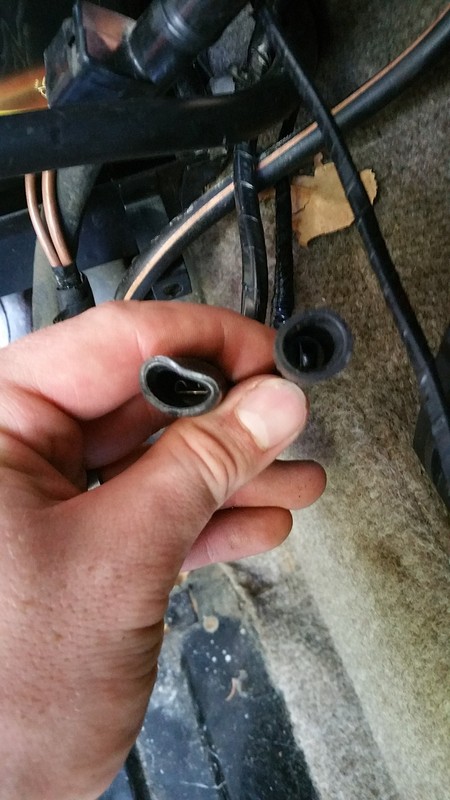
I'm old enough to realize how dumb I am. I don't understand the why's of what I about to write, but tokyodon may have the answer. The wire I bought from Harleys was a very small coax wire. It was about 24-26ga stranded center.
The coax has something to do with hertz. The "sensors" put off some sort of high frequency that can disrupt the signal on surrounding wires somehow.
I am a builder. I don't know why, but we cannot (or aren't supposed to) put low voltage, and high voltage wires in the same pathway/box.
Again, not sure what goes on with the hertz, but there is a guy on another forum, that is a electrical engineer, and as best he could in laymans terms, explained what was going on. All I know, is that someone built a harness for my car prior to me buying it. It had shielded twisted pair, and it simply would not run. The wire I bought from Harley literally looked just like a TV cable wire, only small. Like 1/8" diameter small. I am going to be near there tomorrow, and will see if I can stop by, and confirm for you what I know worked on my car.
Thanks so much guys, let me know what you find! I'm going to try and get all of the other wires run this weekend.
#22
03-20-2015 | 05:57 PM

Senior Member
Joined: Mar 2014
Posts: 137
Likes: 33
From: nevada
I appreciate all of your help and guidance here. If you are near them (please don't go out of your way!) and can confirm what you purchased, I will buy exactly what you got. I am a firm believer in experience, and since you have gone through the exercise I am grateful and appreciative to reap the benefits of your headache. If they can somehow look up your invoice or something and give you some details about what you purchased, that would be an enormous help. I'm not afraid of trial and error, but if I can get the information ahead of time that's all the better.
Thanks so much guys, let me know what you find! I'm going to try and get all of the other wires run this weekend.
Thanks so much guys, let me know what you find! I'm going to try and get all of the other wires run this weekend.
#23
03-20-2015 | 07:23 PM
Veteran Member
Joined: Dec 2013
Posts: 1,078
Likes: 398
From: Greer SC
#24
03-20-2015 | 07:34 PM
Veteran Member
Joined: Dec 2013
Posts: 1,078
Likes: 398
From: Greer SC
I feel reasonably sure we are looking a RG58 stranded center coax. Check this out:
RG58 Flexible Coax Cable Black PVC Jacket
RG58 Flexible Coax Cable Black PVC Jacket
#25
03-31-2015 | 12:48 PM
I didn't see your latest reply until now, Gene. I'm not sure if that's what is on my car currently, but it sure looks like the right stuff. Even if the wire in there now is just shielded wire, this will at least work in the same way that the shielded wire does. Thanks for the info, I'll get a couple lengths of that.
I have completed most of the rest of the wiring, The wires up from the amps and the ignition coils are soldered. Just have the sensors on the top of the motor left (ambient air, coolant temp, crank position, engine speed) and the wiring will be complete.
*edit*
Found some RG58 stranded center coax at the local electronics supply place for $0.70/ft. I'll pick some up tonight. I hope this does it!
Last edited by xjsman89; 03-31-2015 at 01:11 PM.
#26
04-01-2015 | 09:58 AM
Veteran Member
Joined: Dec 2013
Posts: 1,078
Likes: 398
From: Greer SC
Its all good, lol. All I know is my car had a new made harness from a unnamed supplier. They installed a shielded twisted pair wire, and it wouldn't start. Something to do with hertz, RF? The wiring diagram, even on the later cars shows the wires being shielded, but cut a original harness open, and its coax. Starting in 90, it was coax to the amps as well. That, coupled with reversed polarity in the harness of the rear sensor, as well as the sensor being .046 away from the flywheel, the car just wouldn't run. It was a mess. If you look on the plug of the sensor, it has a + sign on one side. Trust me, it matters. Keep us posted
#27
05-17-2015 | 02:00 PM
I've made some progress. The harness is (theoretically) complete with coax in the right places. I put some oil down the plug holes to lubricate the top end. New plugs are gapped and installed, newer coils and wires are in place, and everything on the top of the motor is back together. I have both gas tanks out (lots of rust) but am trying to get it to start with some 91 in a 5 gallon gas can for now just to see if it will run before I wash out/coat the tank with rust inhibitor. I've put on a new fuel filter and changed the oil/oil filter as well. She's cranking now at least, but not firing.
The problem that I'm having now is no spark. I really don't like the thought of my harness that I just re-did being wrong, but I suppose it's possible. I don't have any spark coming out of the coils (tested using an inductive spark tester. Checked the tester, it works on my Olds.) at all. A buddy of mine had a set of newer coils and wires that he gave me, and I tested it with both the new and old (original) coils with the same result.
Is there anywhere that I can look for a potentially simpler fix before I take this new harness apart? I couldn't find any ignition fuses that could be blown. I was working on the interior and I believe I unplugged the inertia switch, could that be a source?
Is anyone familiar with what voltages I should see coming out of the connector to the coils? I could test that as well to make sure my harness is working (or not working) like it should. Maybe I crossed a couple wires or something?
Thanks in advance, as always!
Last edited by xjsman89; 05-18-2015 at 09:28 AM.
#28
05-18-2015 | 05:59 AM
Veteran Member
Joined: Dec 2013
Posts: 1,078
Likes: 398
From: Greer SC
#30
06-10-2015 | 08:45 AM
I've got an update with my situation, and another request for input.
I found my initial problem with no spark, which has fixed part but not all of the issue. It started with only having 12v with key on across the power/ground of amp B, and not amp A. Further testing revealed that I didn't have 12v at the ECU either. In trying to diagnose the problem I tested continuity of all wires going to the ECU (from the ignition harness, anyway) and found that they are all good until it came to ignition/key on testing of power wires. I looked further back in the harness and found that I wired a couple leads incorrectly, and I wired amp B directly to the ignition power instead of branching to the ECU, both amps, both coils, etc. With that problem fixed, I have come to my next problem.
The car has spark and tries to fire, but you can tell that it isn't consistent. A few cylinders here, one or two there, etc. Upon further investigation with an inductive spark tester I have found that I have strong spark coming out of Coil A (lower) but intermittent spark coming out of coil B (upper.) I have 12v with key on to both amps (across power/ground) and coils (across ignition power to the amp signal), but still have intermittent spark out of the upper coil only.
Does anyone have any ideas as to what could be causing this? My only thought is the Green and Green/Purple wires going from the ECU to the amp could be suspect since I have 12v, but apparently one coil isn't getting the correct/consistent signal. Is this where I should be hooking up an O-scope and checking the wave, or should there be a constant voltage while cranking?
I have tried two different coils with no change, a newer one and one of the coils original to the car. I swapped the wiring harness to the lower coil (the one that we know is working normally with strong spark) and the problem followed the plug, not the coil.
Getting closer, but still looking for some guidance! Thanks!
Last edited by xjsman89; 06-10-2015 at 08:50 AM.
#31
06-10-2015 | 11:06 PM
Veteran Member
Joined: Dec 2013
Posts: 1,078
Likes: 398
From: Greer SC
When I went through all of this with my 89 XJS Marelli car, it really came down to two problems. First, the rear crank sensor had somehow had its polarity reversed, and second, the rear sensor was too far away from the crank. The first was easy once I found the problem, and the second wasn't too bad, just slow. I had to file the mounting boss until I got .020 clearance between the flywheel and "sensor".
My symptoms were during initial cranking, I would get really good fire from both coils. But at 3-6 seconds, I would get irratic spark from the B bank coil, and then lose spark altogether.
The Marelli ECU seems pretty tough. It has built in tables that must be within the working parameters, or it won't work. This means that the front and rear "sensors" have to be good, as well as properly gapped. These little fellers are 26-28 years old now, and the magnets get weak over time. Not sure if any of this helps, but keep it up, you'll get it.
#32
06-11-2015 | 07:38 PM
Thanks for the info. I suppose I might have reversed the polarity of one of the sensors, I think I got it right but I'm not positive. I tested the voltage across them with key on and didn't get anything to check polarity with. If I bumped it until the crank was at TDC, would I see a voltage then to check polarity with? The diagram shows the negative (shield) on one side of the TDC and the other side of the flywheel sensor... I wonder if that's for the sake of the diagram or if they are actually showing which side is grounded. I wish I had a car to test it on! I guess I could reverse the wires and see if the car starts?
#33
06-12-2015 | 01:33 AM

Veteran Member
Joined: Jan 2012
Posts: 13,632
Likes: 9,478
From: France
Excuse my asking if this has already been covered, but have you tried swapping the amps? If the fault moves with the amps, then it is the amp at fault. A poor spark on one bank with the Marelli system can be caused (as well as by the other things you are testing for) by a faulty amp. Also a faulty amp plug will cause it.
As I said, apologies if this has already been covered.
Greg
As I said, apologies if this has already been covered.
Greg
#34
06-12-2015 | 11:01 AM
Veteran Member
Joined: Dec 2013
Posts: 1,078
Likes: 398
From: Greer SC
I don't think the amps are the problem here. If you look closely at the crank sensors, they have a + symbol on them. These aren't sensors!!! They are a small magnetos that produce AC voltage. The computer uses this AC voltage to compute timing and pulse rate for the Lucas ECU to feed the injectors. When my car had the rear crank "sensor" reversed, it produced a weird firing. Once repaired, it fired right up. I had one of the vendors that builds wiring harnesses tell me it didn't matter, but I now know this simply isn't true. Makes me wonder....
#35
06-12-2015 | 11:12 AM
Excuse my asking if this has already been covered, but have you tried swapping the amps? If the fault moves with the amps, then it is the amp at fault. A poor spark on one bank with the Marelli system can be caused (as well as by the other things you are testing for) by a faulty amp. Also a faulty amp plug will cause it.
As I said, apologies if this has already been covered.
Greg
As I said, apologies if this has already been covered.
Greg
I will try to get down to the sensor and see the positive markings to check polarity, thanks for the tip. The only things that I can see easily (from the top side, anyway) are the ends of the extenders, not the actual sensors themselves. I was also checking for voltage in DC, not AC. I forgot that they were AC sensors. I will check the AC voltage under cranking and see what we get. Is this best done with an O-scope?
#36
06-12-2015 | 08:00 PM
Veteran Member
Joined: Dec 2013
Posts: 1,078
Likes: 398
From: Greer SC
A oscope is what is recommended. You don't have to get to the sensor, just the plug. If you put a analog meter across the two terminals of the "sensor", you should get a sweep of the gauge when you spin the engine over. A digital meter is useless here. The factory manual shows what the oscope should look like with a correct signal. Thats how I found my second problem. It just didn't look anything at all like what the manual showed.
I can really understand your situation. I bought my car on eBay as a non running project that had been at the hands of some real butchers when it came to the harness. Then they had a "new" one built by a guy that builds harnesses. When it didn't fix it, they cut into the "new" harness, trying to get it running. It was a mess made messier. Building anew harness was all I knew to do. Anyway, after maybe 40-50 hours of trial and error, the car still wouldn't run. It was somehow a fluke that I saw the + sign on the sensor pigtail, and then realized they had to be wired with correct polarity. Because I was chasing ghosts it seemed, I somehow came across the info on another site that suggested the clearance of the "sensors" to the flywheel, and the fingers on the front. As best I could, I filed the mounting bosses to get as close to .020 as I could, although the front one I simply couldn't because the fingers were different. I got the tightest tolerance to .020, but the others were .027, and .034 if I remember correctly. Anyway, these two things sort of happened on the same day, and when I tried it that day, it fired right up!
I wish I could offer more help, but its about all I can tell you. Check, recheck that Marelli harness. It will happen.
#37
06-13-2015 | 01:55 PM
She's far from complete, but getting there. I'll keep posting with progress!
Last edited by xjsman89; 06-13-2015 at 02:01 PM.
The following users liked this post:
Greg in France (06-14-2015)
#38
06-13-2015 | 05:06 PM
Veteran Member
Joined: Dec 2013
Posts: 1,078
Likes: 398
From: Greer SC
#39
07-13-2015 | 09:54 AM
I got the gas tank back on Friday, put it in, and drove the car a couple times this weekend. She only has a 1 mile trust radius right now so I didn't drive her very far, but that's something right? It was great to get her on the road again. I've forgotten how much I enjoy driving this car. Now to get her tagged and insured so I can actually drive around on public roads!
The guy who has the gas tank has had it for a while, and there are a couple small details that I have forgotten with respect to putting it all back together. Mainly I have these two spade terminals:
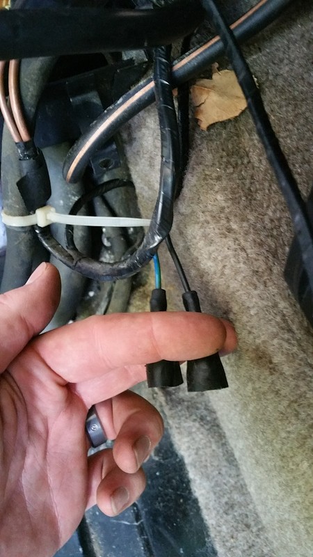
One black and one blue wire. They're in the same loom as the fuel sender wires, at least on my XJS. The wires look like they want to curve back into the little cubby behind the rear tire to the right of the battery. I don't remember what they go to and for the life of me I can't find where they plug into by just looking back there. If anyone remembers and can give me quick pointer, that would be excellent!
The guy who has the gas tank has had it for a while, and there are a couple small details that I have forgotten with respect to putting it all back together. Mainly I have these two spade terminals:


One black and one blue wire. They're in the same loom as the fuel sender wires, at least on my XJS. The wires look like they want to curve back into the little cubby behind the rear tire to the right of the battery. I don't remember what they go to and for the life of me I can't find where they plug into by just looking back there. If anyone remembers and can give me quick pointer, that would be excellent!
Last edited by xjsman89; 07-13-2015 at 10:05 AM.
#40
08-20-2022 | 10:37 AM

Junior Member
Joined: Jul 2022
Posts: 3
Likes: 0
From: Pennsylvania
I have a 1985 XJS and someone had cut off many of the wires in the engine compartment. There is a single heavy-gauge white wire with blue tracer which has a connector and it is just floating around inside. There are a few other wires which have been cut off. Also, which wires go to the oil pressure sensor and light? I'm sorry i bought this car, but would like to resurrect it. It has low miles and a good engine. The interior is a mess, no gauges work, windows don't work, but I don't care about that now, as long as it is driveable. I should have gotten the old Corvette.