A/C compressor help/wiring
#21
 04-10-2016, 12:08 PM

#22
04-10-2016, 12:21 PM


Veteran Member
Wire from fuse is going to socket #30,
socket #87 is a green/white wire.
Is schematic wrong?
Also, does it matter?
I tested the really earlier when working on wiring. When A/C was switched on I was getting 12v from the 85 and 87 socket, with AC switch off I only got 12v to the brown/slate wire which is #30.
It seemed to work earlier but after I ran a new wire from the brown/green wire leaving the relay it stopped working.
i must be doing something stupid and/or wrong.
#23
04-10-2016, 12:25 PM

Veteran Member
Andy
The relay is just an electrical switch, with two separate parts: A low amp solenoid activated part that when it gets current throws a high amp switch. So when the low amp pin gets feed from the aircon switch it activates the solenoid in the relay that clonks the high amp switch in the relay to send a high amp current to the compressor clutch.
So the aircon control should send 12 volts to the relay, ignition on. The relay itself is a switch that uses the low current from the aircon control to switch high amp current to he compressor. Therefore the relay should have 12 volts to one side of the HIGH amp part, all the time. This is your permanently live pin 30. The wire from the relay to the compressor carries the 12 volts that is always at pin 30 to the compressor. This wire should be attached to the pin opposite pin 30 on the relay, this is (over here) pin 87.
The wire from the aircon cabin control should be attached to one of the pins on the axis at 90 degrees to the pin 30 high amp pins. The other one should go to earth.
So if the relay works OK, and there is always current to pin 30, then you need a low amp feed from the cabin control to pin 86 (or the pin opposite it, pin 85, the relay does not care) and an earth from the other. Then you should find the pin opposite pin 30 (pin 87 over here) gets live when the aircon is switched on by the cabin control.
This link explains it a bit:
http://www.12voltplanet.co.uk/relay-guide.html
This diagram shows the schematic, but somewhat confusingly, in real life the pins are at right angles to one another, as in this photo on the left:
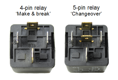
Schematic
Make & break relay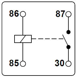 The most simple form of relay. The circuit between terminals 30 and 87 is made on energisation of the relay and broken on de-energisation, known as NO (or vice-versa for a NC relay).
Greg
The relay is just an electrical switch, with two separate parts: A low amp solenoid activated part that when it gets current throws a high amp switch. So when the low amp pin gets feed from the aircon switch it activates the solenoid in the relay that clonks the high amp switch in the relay to send a high amp current to the compressor clutch.
So the aircon control should send 12 volts to the relay, ignition on. The relay itself is a switch that uses the low current from the aircon control to switch high amp current to he compressor. Therefore the relay should have 12 volts to one side of the HIGH amp part, all the time. This is your permanently live pin 30. The wire from the relay to the compressor carries the 12 volts that is always at pin 30 to the compressor. This wire should be attached to the pin opposite pin 30 on the relay, this is (over here) pin 87.
The wire from the aircon cabin control should be attached to one of the pins on the axis at 90 degrees to the pin 30 high amp pins. The other one should go to earth.
So if the relay works OK, and there is always current to pin 30, then you need a low amp feed from the cabin control to pin 86 (or the pin opposite it, pin 85, the relay does not care) and an earth from the other. Then you should find the pin opposite pin 30 (pin 87 over here) gets live when the aircon is switched on by the cabin control.
This link explains it a bit:
http://www.12voltplanet.co.uk/relay-guide.html
This diagram shows the schematic, but somewhat confusingly, in real life the pins are at right angles to one another, as in this photo on the left:
Schematic
Make & break relay
The most simple form of relay. The circuit between terminals 30 and 87 is made on energisation of the relay and broken on de-energisation, known as NO (or vice-versa for a NC relay).Greg
Last edited by Greg in France; 04-10-2016 at 12:57 PM.
#26
04-10-2016, 12:44 PM
Veteran Member
On the solenoids I have, anyway, the low current side that switches the high current side, functions fine whichever of the low current pins is live and earth. The solenoid, in other words switches the same regardless of which of its two terminals is live and earth. After that, as far as I can tell, the wiring will not "know" what the relay pin is doing. If the relay has a diode in it, then maybe it will only switch when the low current feed is to one particular pin low current pin.
greg
#27
04-10-2016, 12:50 PM
Veteran Member
Mac
On the solenoids I have, anyway, the low current side that switches the high current side, functions fine whichever of the low current pins is live and earth. The solenoid, in other words switches the same regardless of which of its two terminals is live and earth. After that, as far as I can tell, the wiring will not "know" what the relay pin is doing. If the relay has a diode in it, then maybe it will only switch when the low current feed is to one particular pin low current pin.
greg
PS - I assume the diode is in circuit to prevent current going back to the Climate Control ECM
Last edited by Mac Allan; 04-10-2016 at 12:57 PM.
The following users liked this post:
Greg in France (04-10-2016)
#28
04-10-2016, 01:04 PM
#29
04-10-2016, 01:07 PM
Veteran Member
Unless the schematic is wrong, it should be at 86.
Could you post a higher resolution photo of the wires going into the relay socket?
#31
04-10-2016, 01:46 PM
#34
04-10-2016, 04:12 PM
No voltage at pin #20. I followed the test procedure in manual and neither of the A/C ECU's I have are putting out 12v at #20.
I think what happened is that I hooked up my compressor wire incorrect earlier and then proceeded to blow both of my A/C ECU's while testing.
We'll see, a new ECU is on the way!
I think what happened is that I hooked up my compressor wire incorrect earlier and then proceeded to blow both of my A/C ECU's while testing.
We'll see, a new ECU is on the way!
#35
04-10-2016, 04:50 PM
Veteran Member
No voltage at pin #20. I followed the test procedure in manual and neither of the A/C ECU's I have are putting out 12v at #20.
I think what happened is that I hooked up my compressor wire incorrect earlier and then proceeded to blow both of my A/C ECU's while testing.
We'll see, a new ECU is on the way!
I think what happened is that I hooked up my compressor wire incorrect earlier and then proceeded to blow both of my A/C ECU's while testing.
We'll see, a new ECU is on the way!
Sorry about that, wish I could help more.
#36
04-14-2016, 05:48 PM
#37
04-14-2016, 11:49 PM

Veteran Member
Join Date: Mar 2008
Location: Pacific Northwest USA
Posts: 24,822
Received 10,871 Likes
on
7,150 Posts
#38
04-15-2016, 04:54 AM
The new A/C ECU sends a signal through green/brown wire to A/C relay under hood, which then sends 12v through the green/white wire to compressor.
On my 89 the green/brown wire from the A/C ECU, or pin 20 on the ECU, wasn't activating when the fan switch was turned on because I'd attached the compressor wire to the wire going this wire, TO the ECU.
On my 89 the green/brown wire from the A/C ECU, or pin 20 on the ECU, wasn't activating when the fan switch was turned on because I'd attached the compressor wire to the wire going this wire, TO the ECU.


