When you click on links to various merchants on this site and make a purchase, this can result in this site earning a commission. Affiliate programs and affiliations include, but are not limited to, the eBay Partner Network.
After a great summer without any problems about two weeks ago the inevitable happened. I was waiting for the traffic light to turn green and the engine just stopped working out of the blue, and after that it just wouldn't start again. Some friendly bystander offered to push the Jag to a safe parking lot (I'm sure he still regrets it probably and having back problems now) and eventually the Dutch AAA arrived.
Apparently the ignition coil doesn't get any spark. The coil itself does work, so it must be something between the ECU and the ignition coil. After a lot of hassle we managed to park the Jag back in my workshop and I started looking for the problem. I used a lot of sources to find out what could cause it, video's from 'Living With a Classic', the sticky doc 'So Ya got a HE V12 that wont start' and several threads on this forum. I am definitely not an experienced mechanic so I really take my time and do everything step by step and really enjoy doing so.
So far I've checked the Coolant Temperature Sensor with my multi-meter and it works properly. I also bridged the plug towards the CTS just to make sure, but obviously it didn't start. Today I wanted to see if there could be internal damage to the cable between the ECU and the CTS-plug. I've looked online and saw that ECU pin number 5 and 19 need to be measured, but that was for an HE-version. My ECU doens't have the same cable plug as that version, but the cables leading straight into the ECU.
Long story short: how can I check the continuity between the CTS-cable and the ECU? Is it possible to unplug the ECU in a different way? Also, since I am again not an experienced mechanic and English is my second language please have some patience with my way of asking questions and the extra clarification I need on simple stuff, I'm learning slowly but steadily!
The Jag is a 1978/1979 pre HE (Vin 101442). I recall having starting issues before, whereby it just wouldn't start until a couple of minutes later or just take it's time in general. On other days it would start even quicker than my daily car, so maybe it's inconsistency with starting might point towards the right direction?
(P.S. Any other recommendations on solving the non-starting issue are more than welcome!)
Unfortunately not as approachable as a HE!
Last edited by TheDrivingDutchman; 10-22-2022 at 06:26 AM.
Hi, first thing to note is that the ignition and the fuel injection systems are independent of each other , with the sole exception being the rotor arm has a magnet underneath it that switches the 2 groups of 6 injector firing , therefore if you have no spark its just a case of checking through the distributor, coil , ballast resistor , ignition amplifier and associated wiring. If you have not got a factory workshop manual(xjs or xj12 will do) then get one! It gives a step by step guide on fault finding but most likely on the pre he set up is the ignition amplifier, these gave trouble even when new due to heat build and Jaguar introduced a modified distributor pick up and amplifier which from memory were not interchangeable.
For future reference regarding ecu wiring, the grey plastic cover on the ecu slides out to enable the harness to be unplugged from the ecu.
Hope this helps
Thank you very much for your reply! Today I have a few hours to kill so I will have a look. I indeed do have the workshop manual as well, will have a look at it.
Just a quick question: when the ignition coil does work but doesn't get a spark, would that mean that the distributor can't cause the problem since it comes after the ignition coil? Or do I have the order mixed up?
The distributor pick up works in conjunction with the coil and amplifier to create the spark so , although unlikely, a distributor pick up fault would mean no spark from the coil. This is covered in section 86.35.29 , all you need is a multi meter and a bit of patience! From experience the most likely fault is amplifier followed by ballast resistor, then coil then pick up module in that order, plus the fact the wiring is over 40 years old and will have been subjected to extremes of heat!
A word of warning, if you do start to work on the internals of the distributor take particular care when removing or working around the injector trigger board that sits under the rotor arm, the plastic screws have a habit of breaking off in the distributor and the trigger boards go brittle with age and when faulty can cause the car to run on just 6 cylinders or not run at all.
Once you have a good spark from the coil then , as Grant Francis points out, a new set of good leads and new oe distributor cap can transform a car. There are a lot of v12’s running around that are not firing on all twelve cylinders ! Also worth checking is the timing rotor wheel to make sure all of the 12 rods are still there,I had a case years ago where a rod had fallen out of the rotor and the car had been running around for quite a while on 11 cylinders .
The Opus pre he set up may have been state of the art technology in the early 70’s but for long term reliability the Lucas CEI system ,as fitted to the HE ‘s prior to the computerised Marelli set up , is a very worthwhile upgrade.
Good luck.
The Plastic Wheel inside the distributor is the trigger for the coil.
Providing the Coil has Volts at the +ve terminal during crank.
The spark FROM the coil goes to the cap, then via the rotor to the required spark plug terminal.
The SMALL carbon brush inside the cap centre post, is common to just "fade away", and then the spark FROM the coil has nowhere to go.
As long as you have spark OUT of the coil, the problem is 99% downstream from there.
HT leads are always a go to, due to age, quality, and heat.
Thanks for the clarification Grant, it makes sense to me now. I took off the distributor cap and saw this underneath:
They seem quite fine to me so far. But as you said, I am definitely replacing all the HT leads. (I tried to measure them but couldn't get a clear reading from my multi-meter, so might as well make sure and replace them anyway). Would you advise to replace this distributor cap as well just to be sure?
Originally Posted by Scd
The distributor pick up works in conjunction with the coil and amplifier to create the spark so , although unlikely, a distributor pick up fault would mean no spark from the coil. This is covered in section 86.35.29 , all you need is a multi meter and a bit of patience! From experience the most likely fault is amplifier followed by ballast resistor, then coil then pick up module in that order, plus the fact the wiring is over 40 years old and will have been subjected to extremes of heat!
A word of warning, if you do start to work on the internals of the distributor take particular care when removing or working around the injector trigger board that sits under the rotor arm, the plastic screws have a habit of breaking off in the distributor and the trigger boards go brittle with age and when faulty can cause the car to run on just 6 cylinders or not run at all.
Once you have a good spark from the coil then , as Grant Francis points out, a new set of good leads and new oe distributor cap can transform a car. There are a lot of v12’s running around that are not firing on all twelve cylinders ! Also worth checking is the timing rotor wheel to make sure all of the 12 rods are still there,I had a case years ago where a rod had fallen out of the rotor and the car had been running around for quite a while on 11 cylinders .
The Opus pre he set up may have been state of the art technology in the early 70’s but for long term reliability the Lucas CEI system ,as fitted to the HE ‘s prior to the computerised Marelli set up , is a very worthwhile upgrade.
Good luck.
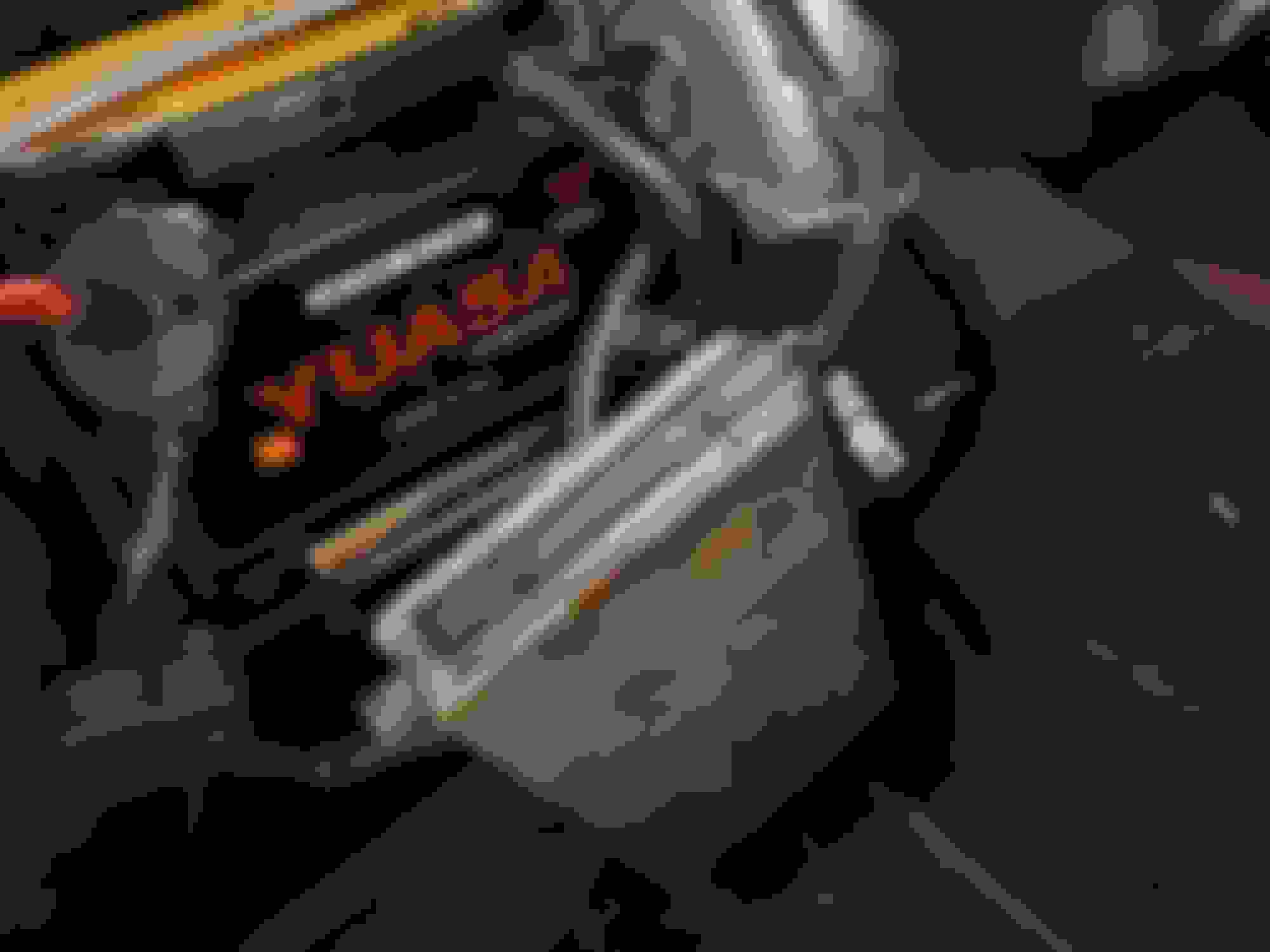
Thanks again for your reply! I found the section that you mentioned, I'm going over them one by one. I wasn't able to track down the ballast resistor though, should it be located near the ignition coil? As per the ignition amplifier on the front; I opened it up to measure it but unfortunately didn't get any further than this:
What would be the best way to measure it, as I can't get to the connecting wires underneath? Or am I making it more difficult than I should?
Hi, yes you are making it a bit more difficult than it should be, certainly no need to dismantle the Amplifier to test it. The Amplifier lead should have one connection going to the ballast resistor and another to the pick up module in the distributor.The ballast resistor should be mounted on the side of the throttle pedestal , this is assuming you have the original set up. A lot of pre he ‘s have been modified with non standard systems so perhaps a general photo of the distributor and surrounding area would help to identify what set up you have. With the standard set up you should be able to test everything with a voltmeter on the ballast resistor and coil + and - terminals and then using the resistance setting on your multi meter check the coil , ballast resistor and distributor pick up as per the manual .
From looking at the last photo it would seem you have the later set up with the Amp mounted on the radiator top panel and the long lead then should run through the centre of the engine with one connection to the distributor and the other to the ballast resistor, although I don’t recognise the shiny part at the bottom of the photo which has 2 red connectors going into it? I am beginning to think you may have a non standard set up!
Hi, yes you are making it a bit more difficult than it should be, certainly no need to dismantle the Amplifier to test it. The Amplifier lead should have one connection going to the ballast resistor and another to the pick up module in the distributor.The ballast resistor should be mounted on the side of the throttle pedestal , this is assuming you have the original set up. A lot of pre he �s have been modified with non standard systems so perhaps a general photo of the distributor and surrounding area would help to identify what set up you have. With the standard set up you should be able to test everything with a voltmeter on the ballast resistor and coil + and - terminals and then using the resistance setting on your multi meter check the coil , ballast resistor and distributor pick up as per the manual .
From looking at the last photo it would seem you have the later set up with the Amp mounted on the radiator top panel and the long lead then should run through the centre of the engine with one connection to the distributor and the other to the ballast resistor, although I don�t recognise the shiny part at the bottom of the photo which has 2 red connectors going into it? I am beginning to think you may have a non standard set up!
Hey, thanks for your quick reply. Good to hear that it's simpler than dismantling the amplifier to test it. So if I'm understanding you correctly, the module I marked in red below should be the ballast resistor, as it's mounted on the throttle pedestal? I was quite confused as it also says 'Amplifier' on the side, so I probably got it mixed up with the Ignition Amplifier. If the ballast resistor indeed is an original one then I should be able to test everything according to the manual like you said!
As per the Amplifier on the front, it is indeed mounted just behind the grille actually. I'm not sure if that's the standard place to put it but it seems better than in between the 'V'. The shiny module with the 2 red connectors going in is the horn by the way (probably aftermarket).
(Not sure what the previous owner had in mind with all those wires)
I'll have another try tomorrow, I'll keep you updated!
Hi, looks like you are getting there! You have correctly identified the ballast resistor, its has ‘Amplifier’ marked on one side to indicate where the connection from the Amplifier is plugged in ! The system looks standard so you should be able to work through the manual and find the fault, I would expect the fault to be either a wiring issue or the Amplifier.
Good Luck
We're getting there, step by step! Today I measured the ballast resistor on both sides. On the Amplifier side it got -3.08, -0.24 and -0.24 (from top to bottom). So then I measured the supply to the SW terminal, which gave the readings as seen below. So then I can conclude that the ballast resistor doesn't seem to be the problem, but one of the three wires (right?).
I checked the blue/white wire to the relay, which had continuity. So I guess that does that mean it could be the relay itself? I checked the manual as well and the white/twisted blue wire goes to the rev counter, which is interesting as the needle from the rev counter would jump up and down a few weeks before the engine stopped. So that's interesting I guess.
I'm not sure where the white wire goes, I figured I would check the relay and rev counter first. Would you guys suggest that I replace the relay and work from there?
Hi, a simple check would be , with ignition on, to check you have 12 volts ( battery voltage) at each of the terminals of the Amplifier side of the ballast resistor. If not then the problem is either the direct feed from the ignition switch or a faulty resistor.
if you have 12 volts on the Amp side, reconnect the socket to the resistor then unplug the small connector that comes out of the distributor and goes into the Amp lead. Then with ignition on check voltage at + terminal on coil, you should have 4 to 6 volts. A reading higher than this means either a faulty coil or Amp .
You said the coil was good so a simple check for the Amplifier is , with ignition on, check voltage between the coil - terminal and earth.should be 0 to 2 volts. If you have 12 volts the amplifier is faulty.
The relay in the photo you refer to is the starter relay and this will only give voltage when the starter is engaged.
The white wire in the photo with the ? mark is the direct 12 volt feed from the ignition switch.
Again good luck
Well, it seems that the amplifier is faulty indeed! It reads almost 12 volts between the coil - terminal and earth. Thanks again for all the clear explanations, you really helped me out! I will be ordering new HT-leads, distribution cap, rotor and an ignition Amplifier soon.
One last question: would this DAC2673 fit on my pre-HE? It seems to have less outgoing cables than the one I currently have. (I searched this forum for the answer and there were also some suggestions of replacing the ignition module inside the amplifier, but a quick Google search tells me that the suggested AC Delco part won't fit in my Amplifier as seen below.) So I guess it's time to replace the whole module. Not sure if the DAC2673 will fit mine (Vin 101442) though!
Hi, good you have found the problem. The Amplifier part number you need is/ was DAC1371, whether you will be able to find one is another matter, which is why a lot of uk pre he’s and E types end up getting converted to the Lucas constant energy system which is what the Amp you are referring to(DAC 2673) is for. This Amp is not compatible with your existing set up.
If you cannot find an original Amp then you either go totally aftermarket as a lot of owners in the USA do, or the Lucas HE route.
if you decide on the Lucas you can either buy kits from several UK suppliers which use the HE bits inside an Opus housing to give the original look. If you are not bothered by originality then fit an HE distributor but with your vacuum unit and trigger board . Unfortunately either way is not going to be cheap, to such an extent that you may be able to pick up a complete but rusty HE XJ12 for not a lot more and that would give you an abundant supply of other mechanical parts.
The joys of owning a V 12!
All the best Simon
Well, I suppose I should see it as an investment! I actually just found a new OEM DAC1371 Amplifier in the US and ordered it straight away. It does cost a lot but that's indeed the price of wanting a V12. Still worth it! (Indeed I would have preferred an old and rusty XJ40 on the side, if only I had more space...)
Thanks again for everything Simon, I'll keep you posted!

 10-22-2022, 06:16 AM