When you click on links to various merchants on this site and make a purchase, this can result in this site earning a commission. Affiliate programs and affiliations include, but are not limited to, the eBay Partner Network.
Both Transistor legs are as follows
Centre pin B
Outside pin C
Other outside pin E
ZTX650
Red Probe to B and Black Probe to E about 0.6V - 0.75V
Red Probe to B and Black Probe to C about 0.6V - 0.75V
Swapping Probes so Black to B should give no reading or open circuit - correct open circuit 0V
C to E one way will read 0.6V and open circuit the other way - average was 0.25V BOTH ways (high was 0.29 and low 0.21)This was on both diodes
ZTX750
Exactly the same but the probes are swapped, so Black Probe to B and Red Probe to E will give 0.6V etc.Same as above - both read the same.I have no idea which as which.- I read them from underneath the circuit board just in case that makes a difference Are these the diodes? Tested the 6 soldering joints.
Both Transistor legs are as follows Centre pin B Outside pin C Other outside pin E
ZTX650 Red Probe to B and Black Probe to E 0.6v Red Probe to B and Black Probe to C about 0.6v Swapping Probes so Black to B should give no reading or open circuitCorrect NO voltage C to E one way will read 0.6V and open circuit the other wayCorrect
ZTX750 Exactly the same but the probes are swapped, so Black Probe to B and Red Probe to E will give 0.6V etc.
Black Probe to B and Red Probe to E 0.003v Black Probe to B and Red Probe to C about 1.47v Swapping Probes so Red to B should give no reading or open circuit0.6V one way and 0.003v C to E one way will read 0.6V and open circuit the other way0.6v one way and 1.06v
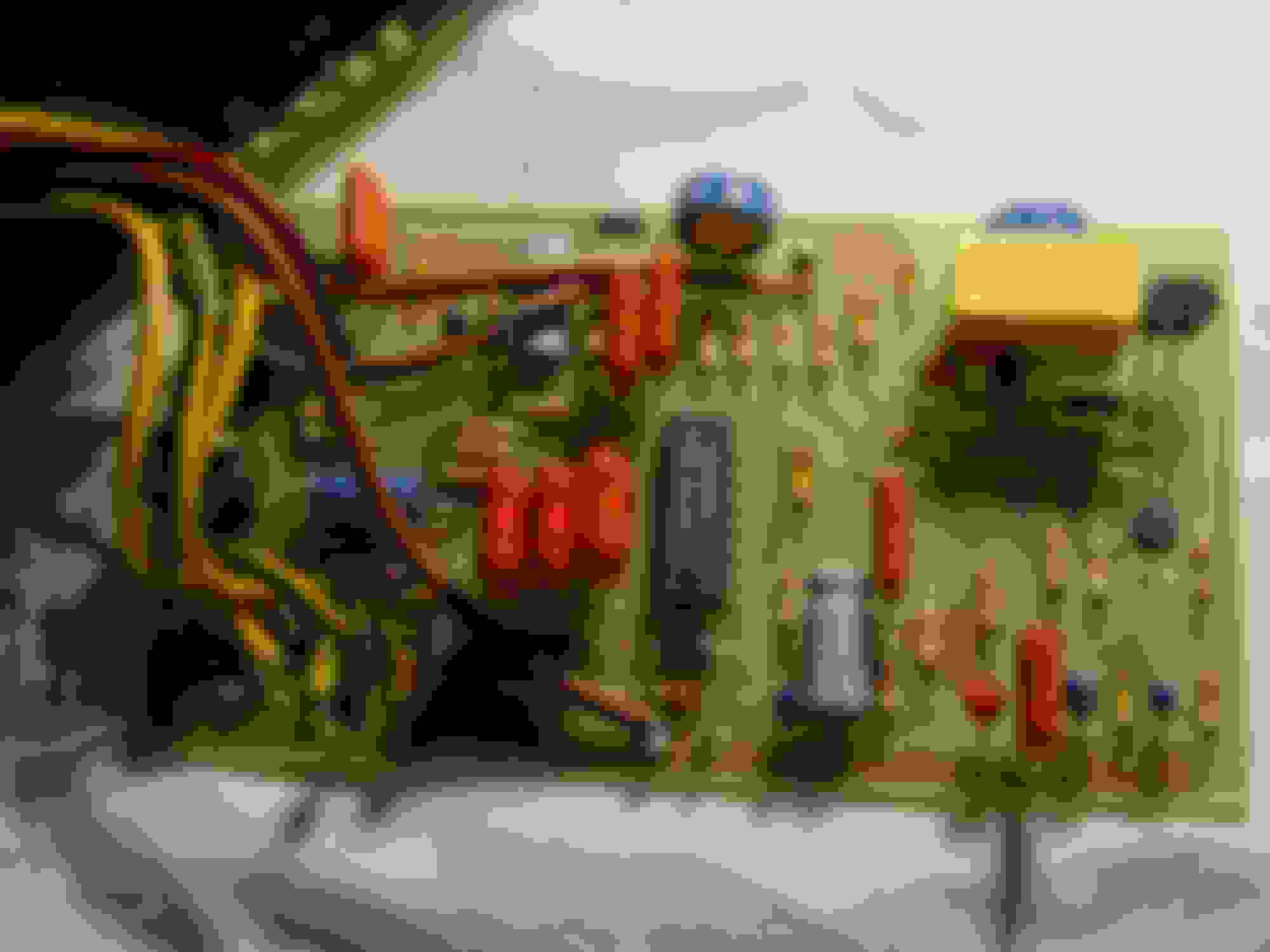
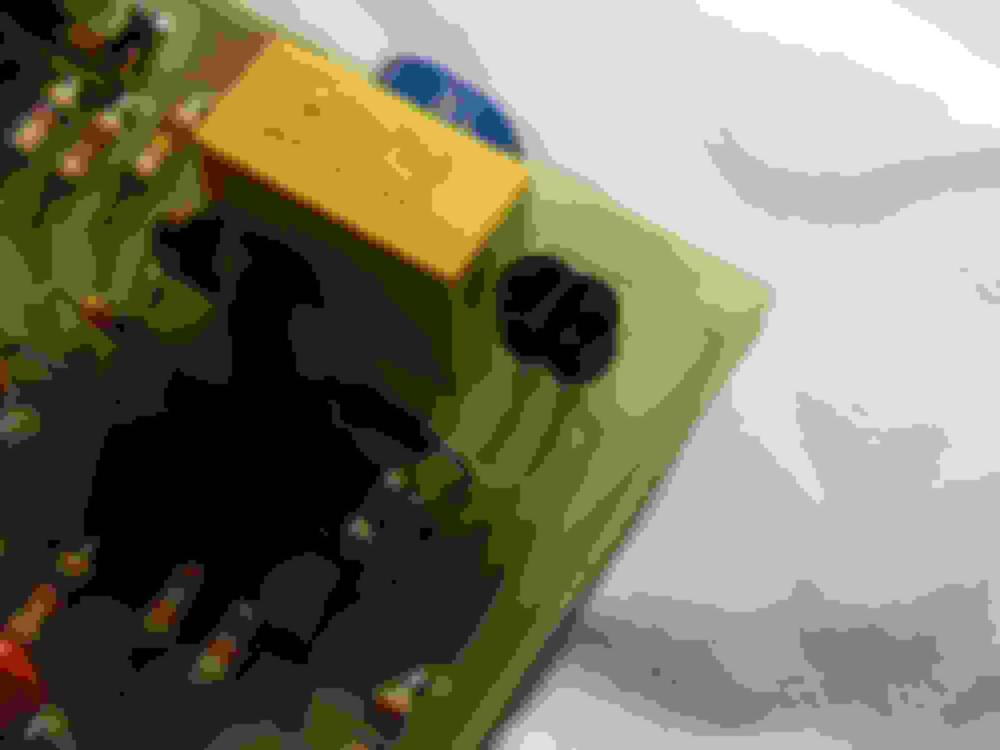
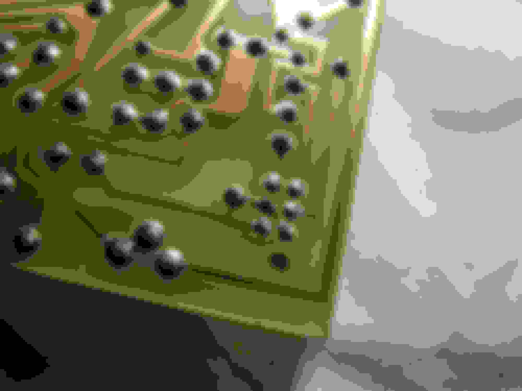
The ZTX750 is bad and will need to be replaced. While you are at it test the diodes circled in red, they should test the same as the transistors 0.6V one way and open circuit the other. Post the voltages for each diode so I can see what they are.
Ok they are good. get another ZTX750 and hopefully that will fix your problem.
To replace the transistor cut the legs off, makes it easier to de-solder. Put solder on the iron tip before you put the tip to the work then pull the legs out with pliers.
When you install the new one make sure it goes in the correct way.
I have done A/C to a buddy’s XJ-SC V12 ‘85. He told me cruise control had stopped working and that the bellow was cracked. Easy to change while I had the compressor out, so I sourced a used unit.
Now fitted, and still no CC
I measure 22-23 ohm from middle connector pin to each of the 2 side pins, and both solenoids operate with a 9V battery.
When I activate the vacuum supply solenoid, the vacuum is not sucking in the bellow. Is the other solenoid normally open and thereby dumping the applied vacuum until it is activated ?
With engine running and CC switch in ON position I have 0V on all pins in the connector.when stationary. Does that sound right ?
All fuses under LH (driver) knee pad checked for continuity.
I have not read manuals or been very systematic, sorry. It’s raining, and I expected it to be a 10 minutes job...
Edit: Forgot to mention my own XJ-S does not have CC, so there is no reference available...
Last edited by leo_denmark; 05-30-2019 at 09:34 AM.
Yes one solenoid is NO and the other is NC so voltage needs to be applied to both to hold vacuum.
All which pins the ones at the bellows or the ones on the CC module?
Thanks Warren.
I�m working in R&D developing solenoid valves, so the terms NC and NO are clear to me, but I didn�t want to risk getting less answers by using them in my question...
I haven�t located the CC module yet, so I�m measuring at the bellow connector. I guess next step is to make a small test lamp setup as described in earlier post and go for a drive.
Leo, I haven’t located the CC module yet passenger side foot well look up, its all there. At the back, black box, two plugs, one big multi, the other a single. hope that helps.
Duke, to get that old ZTX out cut the legs off tin your soldering iron tip then put it on a solder pad and pull the leg out. Do this for the others re-tinning your iron between each.
When you have them all out you will need solder wick to remove all the solder from the board holes before you try to install the new ZTX. Again tin the iron tip as this puts flux on the iron tip. then put the solder wick on the board and touch it with the iron. Be careful not to leave the iron on the PCB too long or you will lift the pads off the board.
Thanks Warren.
I�m working in R&D developing solenoid valves, so the terms NC and NO are clear to me, but I didn�t want to risk getting less answers by using them in my question...
I haven�t located the CC module yet, so I�m measuring at the bellow connector. I guess next step is to make a small test lamp setup as described in earlier post and go for a drive.
It is on the passenger side under the shin trim, a black box about the size of a 20 cigarette packet, and has a label on it saying "econocruise".
Thanks Warren.
I�m working in R&D developing solenoid valves, so the terms NC and NO are clear to me, but I didn�t want to risk getting less answers by using them in my question...
I haven�t located the CC module yet, so I�m measuring at the bellow connector. I guess next step is to make a small test lamp setup as described in earlier post and go for a drive.
I have been repairing electronics most of my life so tend to reel things off without thinking sometimes as I have been doing it so long. lol
You will have no voltage at the bellows pins until the CC is activated. This will not happen until the car is travelling over 40km/h. I would suggest removing the CC unit and checking both ZTX transistors, they are quite susceptible to failure as any high current draw from a short or jammed solenoid valve will have them fail.
I will see how far I get into the fault finding, the car is being picked up tomorrow. Faulty CC-module sounds plausible. It’s not that easy to analyze things, that needs to be moving at 40+ kmh to start working...
Leo
Last edited by leo_denmark; 05-31-2019 at 09:36 AM.
Econocruise box located and opened. Looked very fine. No testing done to the diodes and transistors.
Connectors was clean, and the fuse was also OK. I cleaned the ends and holder, just in case...
Test drive: no change.
The issue will then most likely be the transistors or the brake switch, which I will check next. If that is not the cause I will tell the owner, that I didn’t manage to fix it this time. He says it’s ok, he’s not using it often. I would, I love to use CC and relax my right foot on long drives...
Thanx for all your input !
 05-05-2019, 12:00 AM