When you click on links to various merchants on this site and make a purchase, this can result in this site earning a commission. Affiliate programs and affiliations include, but are not limited to, the eBay Partner Network.
Since the recent acquisition of my '93 XJS 4.0 coupe I've been hearing a relay clicking behind the glovebox every 60 seconds or so, and two clicks about 3 seconds apart every time I apply the brakes. Any time this relay behind the glovebox is energized it momentarily pulls the voltage down from 15 to 13 volts and all interior/exterior lights dim briefly, so it must be pulling some serious current. Under moderate-hard braking both the "Anti-Lock" and "Brake" dummy lights illuminate so I was clued in to a potential ABS issue.
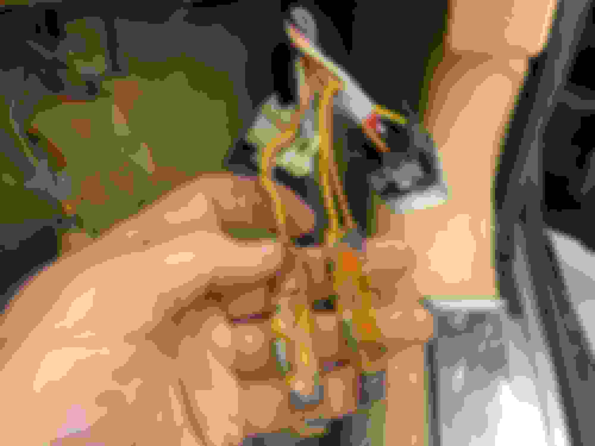
What I found behind the glovebox was a yellow relay labelled "ABS" with some interesting mods. The solid white wire and blue wire have been spliced together with a diode in between. A white/purple wire is then spliced into the other end of the solid white wire via another diode and a section of the blue wire. I have, as of yet, been unable to locate the other ends of the blue and white/purple wires.
Two other relays have been spliced in a similar arrangement; a diode and what appears to be a resistor between the splicing of the yellow and brown wires on both.
I am unsure of the function of any of these relays or what the purpose of these mods to the wiring might be other than to mask an expensive ABS issue. I suppose the first step is to revert the harness back to how it should be and see what is revealed.
All of my previous experience with the XJ-S is pre-ABS so any help here is greatly appreciated. My manuals are all for the V12 HE models so I lack the 4.0 supplement and wiring schematic. If someone could provide an electronic copy of the wiring diagram I could probably sort this out relatively easily.
Jaguar used those wired diodes on a number of the car relays. I haven't looked up the wiring diagrams but they are probably original rather than modifications.
Drop me a PM with your email address and I'll send you the files for the 4 litre.
As noted, those are reverse current protection diodes from when inductive loads switch, and were probably external because at the time, they weren't sourcing relays with them mounted internally:
From the 1993 Model Year Update PDF:
I would think the only one that should click from time to time is to engage the pump relay which refills the pressure in the "bomb" reservoir. So a question might be WHY does it need to be refilled because generally yours supposed to get I think as much as 20 pedal presses out of the braking system with no power too it before the bomb is blead of it's boost ability. The pressure switch would be what tells the relay to activate. So that's where I'd be looking. Is my pressure bomb not able to carry the charge of nitrogen pressure (like an old well pressure tank dying) or is there an issue with my combined pressure switch. Just best guesses.
Note that the Yellow Pump Relay has a diode/resistor combination across pin 85 & 86, and then an external diode to the switch inline on the White Purple wire.
~Paul K.
Last edited by FerrariGuy; 12-10-2022 at 02:10 AM.
My knowledge of electrics is pretty poor but I do know that a diode only allow current to flow in one direction. If you follow the ALBS wiring diagram along the wires you can see that the diodes are essential in turning the system on and off under the various stages of operation. Quite clever really.
Thanks everyone for the advice and the documentation. It did cross my mind that the inline components could be factory, but after seeing the mismatched wires I put it out of my mind. Since my purchase I've been trying to decide if the brake pedal feel isn't just a bit too firm. FerrariGuy's hypothesis about the accumulator failing would explain both the frequent relay triggering and the firm pedal. I ordered the GM substitute accumulator others have had success with on the forum. $93 vs $700 from Jaguar. Will report back.

 12-09-2022, 03:52 PM