When you click on links to various merchants on this site and make a purchase, this can result in this site earning a commission. Affiliate programs and affiliations include, but are not limited to, the eBay Partner Network.
I just completed a test on the Y/W wire from the engine bay to the trunk of car. TEST DONE WITH TPS DISCONNECTED FROM LOOM
The wire is not shorted to power anywhere.
I ran a wire over the top of the car from Pin 7 of the ECU harness and the Y/W wire had continuity. No shorts anywhere.
I peeled back the insulation on the Y/W wire at the ECU plug and this is what I saw.
The color does not show up well in the photo but it is the Y/W wire. With the Y/W wire complete I still had the voltage shown.
Next I cut the Y/W wire and connected the DVOM to the part of the wire going to the ECU and this is what I saw Voltage reading from ECU on the cut Y/W wire
DVOM connected to cut Y/W wire going to the ECU
Since the voltage is coming from the ECU I believe I have a problem at the ECU. Should I open the ECU to see?
From the trunk to the front of the car the Y/W wire has continuity.
More thinking before plugging another ECU into the car.
That YW wire at the rear. Open up the loom, about 6" or so from teh Multi plud, enough to repair this wire after what i suggest.
Cut that wire.
Volt test each cut end, TPS unplugged.
Which end has volts, Engine bay, or ECU. Just in case there is a strange pick up somewhere.
If that volts is from the engine bay, there is an issue there I reckon.
A very dim, and I mean VERY DIM bulb tells me that the Pin #7 YW is the 5v reference, and should show 5V at the ECU cut end.
As with the wires at #5 and #21, being the 5V reference for the CTS and ATS.
My notes have no more info, its just the Grey Matter remembering a very long time ago.
Grant, Sanchez
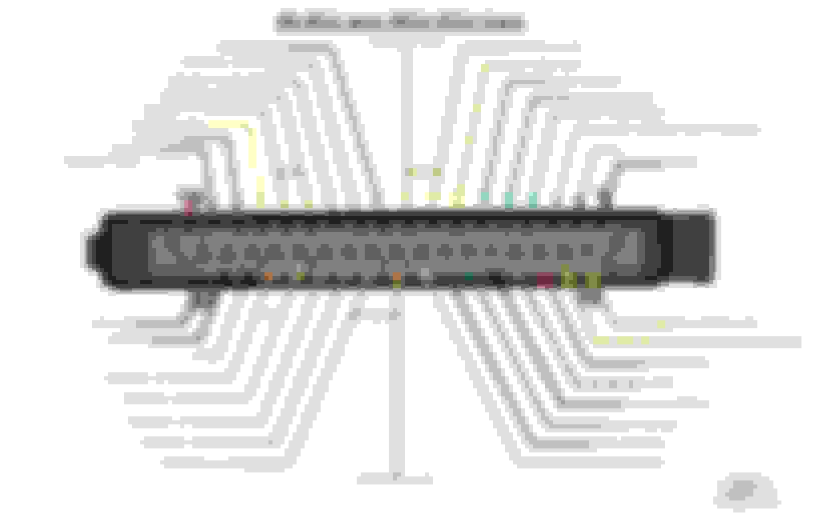
I have just dug this out, which is quite a clear diagram. Pin 7 is for certain the throttle pot wiper signal going FROM the TPS TO the ECU. The 5 volt input to the TPS comes from pin 20.
I fully concur with Grant's suggestion to make 100% sure that the pin 7 wiper signal wire (YW) is not picking up a short anywhere.
Pin 20 (not pin 21) is the 5 volts to the TPS and the ATS.
Pin 5 as Grant said, is the
input volts to the CTS
Thanks Greg. I have it. This morning, using the above diagram I started to look at each circuit from the ECU connector.
I found it on the Jag-lovers forum under the post "INJECTOR NOT OPENING"
There are very clear instructions how to test the various circuits.
I checked, doublechecked and triplechecked the Y/W circuit and there is no problem with the wire from the the ECU Pin 7 to the engine bay and it is free from shorts.
The 3.45 volts I see on the Y/W wire is coming directly from the ECU. I cut that wire about 4 inches from the ECU plug and tested it there.
I will be systematically going through the various circuits to see if I find anything.
I am in the process of revisiting my homemade injector harness connections. I have a dumb question. my query is about the connector in the middle of the diagram.
The connector shown in the diagram above is which half?
Is it the half of the connector wired to the injector harness or the half coming from the loom on the right inner fender?
It does say "12v Power from main relay"
I used this and numbered the half of the connector going to the injectors.
Does it matter? It's dark outside now so I can't check whether there is a difference in both halves.
Also, I have 2 resistor packs and on the 200m scale the impedance on both units ohm out the same 5.5 m ohms.
Ben: Based on the diagram I have the injectors wired correctly.
Grant,Greg, Ben:
I received the "LOANER" ECU (DAC4585) today. Whether the ECU is good or not, I don't know. The owner does not know either.
*The Y/W wire on the loom is good. No shorts, no bad insulation etc. The voltage I mentioned on the Y/W wire is definitely coming from the ECU. As stated earlier, I cut the Y/W wire about 3 inches away from the ECU plug and with the key on I get 3+ volts on the wire coming out of the ECU with the TPS disconnected. With the loaner ECU connected, the Y/W wire which I cut from the loom at the ECU I now get 1.7v. I reconnected the Y/W wire and I measure 1.7 volts in the engine bay.
I also believe that I have a bad TPS but that should not prevent an injector pulse from occurring. I will deal with the TPS issue later. I have to get a new TPS.
BTW: No vendor has the adapter for the Red TPS and the OEM (black) TPS cost more that I paid for the car. (I am thinking 1987 Ford Mustang 2.3L TPS)
The other option is to buy the Red TPS, and figure out a way to get it to work.
*As stated earlier, I have spark. The engine runs with starting fluid. When the engine runs the TACH works. That tells me that a pulse is present. My analog voltmeter connected to the DWW also shows that an pulse to Pin 18 is present. While cranking the engine the needle goes back and forth (how accurate? I don't know). I have 2 AB14s and they both do the same thing. They both have new ignition modules and the condensers have been removed.
I connected a length of speaker wire from the DWW output at the AMP directly to Pin 18 as shown in the photo below. Still, NO JOY. Drilled a hole on the connector casing and went directly to Pin 18
* I went through every circuit from the ECU connector using the diagram that Greg sent me and everything is as it should be. All circuits are in good condition. All grounds are clean and tight in the trunk and the ground circuits to the ECU are present at the appropriate pins.
* Up front the fuel injector harness is connected to the correct wires on the plug. With the key on I have 12v on all 8 wires and 12 v on all 24 injector terminals.
*I have 12 v at all 8 terminals on the resistor pack. I have 2 resistor packs and they both show the same readings when I ohm them out.
* I guess I am missing something simple and I might be overthinking this whole issue.
I have another loaner ECU 16CU coming tomorrow DAC4118.
Any suggestions as to why the ECU is not pulsing the injectors?
I can't help thinking that we're missing something basic - temperature sensor? does the fuel pump even run ??
You shouldn't have any volts on the wiper at all unless the throttle is open - that 1.7 voltage is still there with TPS disconnected - what happens if you ground the signal and then release ?
Ben, that voltage is coming directly from the pin 7. I have the TPS wiper wire cut at the ECU. Nothing connected to it. The Y/W wire from the point where I cut it in the trunk to the Engine bay test good. No short to ground.
The CTS circuit is also good. I installed a new sensor and I also tested the CTS circuit by jumping the terminals with a paper clip.
Every circuit from the ECU plug to the front of the car all test good. No shorts to power, no shorts to ground.
Based on what I am seeing neither the TPS or the CTS circuits should prevent the ground path from the ECU to the injectors from happening.
* The 6cu ECU had a reading of 3.43 volts at Pin 7 and the 16cu ECU has a reading of 1.7 volts on pin 7. These 2 readings were taken at the Y/W wire which is cut so it is isolated from the rest of the car.
Tomorrow I will install a second 16cu ECU and see what is happening at Pin 7.
I still think that even if there is a problem with the TPS signal, that should not prevent the ECU from firing the injectors. This is where I test Pin 7 The Y/W wire is cut`
Wish I could be more use here, I'll see if I can get power onto my spare and see what volts I have on pin 7.
I'm not sure how the ECU decides to fire them together - rate of rise or voltage change - have you tried feeding pin 7 the 5 v source from pin 20 - not sure you'd be able to hear anything from the back though - maybe put the connect at the ECU then disconnect TPS and put the +5V to the signal wire direct - on the wires to the ECU.
On my spare 16 CU I have a standing voltage of 1.34 Volts on pin 7 but it provides negligible current to TPS ground so I think this could be is an impedance thing and a red fish ... I'll try to connect it to a TPS and see what it does ...
Ben. Appreciate your efforts.
I forgot to answer one of your queries regarding the Fuel pump.
Key 'on' pump turn on, then shuts off> normal
Engine cranking pump turns back on.
I have removed the pump relay while I perform all of the tests.
I do not want the pump running until I get the injectors to work.
I cleaned out the main tank and the fuel sump so I have no fuel in the car and running the pump with no fuel is not a good thing.
I don't think the fuel pump has to be running for the injectors to function. Am I correct?
BTW: If I connect my test light to ground and I probe the DWW connector, every time I probe the DWW connector I hear all the injectors click.
Sanchez
The pump does not have to be running for the injectors to click. A dry pump will fail in about 15 seconds, even if it takes a week or two to actually fail, so be careful.
As the injectors click when the DWW sis grounded, Are we missing a GROUND connection from the ECU? The ECU earth connection is pin 1 and on the above diagram, and this is working I think, but the injector earths are pin 35 and the one next to it. Maybe verify these are good grounds? Worth checking the pins, the plug connector, the ground wire to where ever it goes?
Greg. All the ground circuits function as designed. I checked the grounds on Pins 1, 16, 17, 34, & 35 to G6 and they all have continuity.
CTS circuit is also good. I read that we can sometimes get confused with the CTS and ATS circuits. However, my CTS had a white connector and the ATS had a black connector.
I had to replace the CTS connector and CTS because when I disconnected it the pins were rusted out completely. I will revisit the CTS circuit to make sure the 5v reference wire is in the proper position. Does it matter on which terminal of the CTS the 5v reference goes? The reason I am asking is the diagram shows the Y/B wire(Pin 19) as the TPS/CTS ground signal and Pin 5 as the CTS input signal.
Thanks Grant, I will check that out.
In one of your posts you stated the following: "That signal wire from the ign amp unlt only takes over once ignition pulse is available. There is a supplemantary wire from the starter relay to "wake up" the ECU during cranking, and that can be a dud due to dirty contacts inside that starter relay".
In the diagram above (post #162) from Greg, I see a W/R or a R/W wire going to pin 26 that says 'start signal from starter relay'. I guess I should see battery voltage on that wire and at Pin 26 with the key 'ON'.
It never crossed my mind to check that circuit from the starter relay back to Pin 26.
In the diagram above (post #162) from Greg, I see a W/R or a R/W wire going to pin 26 that says 'start signal from starter relay'. I guess I should see battery voltage on that wire and at Pin 26 with the key 'ON'.
You should see battery voltage on that wire and at Pin 26 with the key to 'START'.
I did the test with a TPS connected to my spare ECU and the voltage present on pin 7 dropped to 0.34 as it should so the standing voltage on pin 7 I had when disconnected is within spec once a TPS is connected (my TPS is mounted and 'adjusted').
 10-16-2021, 07:15 AM