When you click on links to various merchants on this site and make a purchase, this can result in this site earning a commission. Affiliate programs and affiliations include, but are not limited to, the eBay Partner Network.
I have started to wire my fans and realized that I don't know what I'm doing, so its time to ask for help. I see three ways of doing this, and I'm not sure which is best. There is a wiring diagram that came with the fans, there is another similar but not identical one that Thorsen posted, or there is a separate control module that he ended up using. I'm going to disregard the separate module for the time being. I'm sure its great, but its out of stock and I want to get the car going.
So, the main difference I see between these diagrams is what happens with the wire from pole 86. It either goes to the ignition or to ground. Why? If it goes to the ignition I assume that the fans will only run when the ignition is on. Is that correct? If it goes to ground does this imply that the fans can run with the ignition off if the sensor calls for them? This seems like it could be a good thing, more post shutdown cooling, but maybe I'm wrong and it won't run after shutdown.
So far I have the fans wired to the relays and to ground, the sensor wired to the relays and to an override switch which is wired to ground. I also have the battery positive wires to the terminal by the cam cover, but I need to get another connector before they can be fitted up.
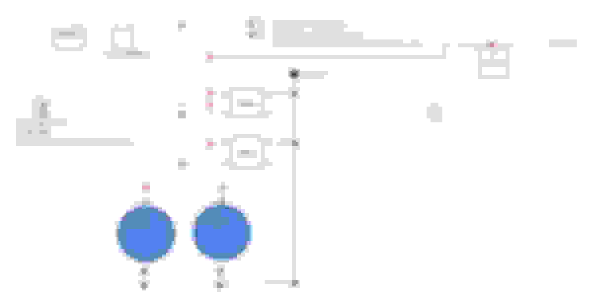
Here are the diagrams:
Think of 85 and 86 as the on/off control for the relay. If 12 volts flows into one of those and finds ground on the other one, it turns the relay on.
30 and 87 are what is switched. In this example you have 12 volts on 30 waiting to go to 87 when the relay is turned 'on'. 87 sends power to the fans.
In the Spal diagram, when the key is on 12 volts flows into one of the 85 or 86 terminals. When the temp switch closes and grounds out, the path through the relay is complete and turns the relay on. When the relay is on, power flows to the fan.
If you wire up 85 or 86 to the ignition key, the fan(s) will only run when the key is in the ignition.
If you wire up 85 or 86 to the battery, the fan(s) will run when ever the temp switch is closed.
My reference is to wire it up to the ignition key so the battery isn't drained.
I just noticed that in my diagram there is a missing diode or relay in the AC circuit. The way it's drawn now will back-feed 12 volts to the AC compressor.
What year is your car? On my 1989 there is already a switch in the water pump "in" fitting. That switch gets ignition key power and when the switch closes, it lets power flow to terminal 85/86 of the fan relay. But you can use the 12 volt power from this switch for what you're trying to do.
Ok, I'm still confused. I found the two wires going to the temperature switch, presumably I want one and not the other. But which? Or I could go back to the diode, and delete some wiring. Or? The car is an '87.
I've been looking at the diagram and I'm not sure what comes from the ignition and what doesn't. Anything that goes to ground obviously doesn't, but electricity is not my strength (clearly). 90 is the fan switch, 91 is the blue diode that looks like but isn't a relay, 133 is the fan relay, 134 is the fan motor. Now I'm pretty sure I don't want the brown wire going to the fan relay, that's going to be 12v and I've got that elsewhere. So one of the wires going into the diode seems likely, but how do I identify which one?
I have stayed out of this, as others are advising you.
I did mine and many others, the VERY simple Aussie way.
One fan is thermo only, RH
The other fan is A/C only, LH.
NO diode, etc etc, just a stand alone wiring system, 2 relays, 2 thermo circuit breakers, wire and terminals, that was simple to do, WORKS, and even simpler to troubleshoot IF its ever needed.
If you want instructions and a "mud map" (trust me the "mud map" will be a "mud map"), just ask, I will write it up and attach here. The drawing will be ROUGH, one eye and some shakes, will do the trick.
Gareth
You DO need the two wires that go to the water pump inlet switch. One carries the current TO the switch (and is live when the ignition is on) the other one carries it to the relay to activate the relay you should hve fitted (which the high current part of actually sends the current to the fan). Thus, when the temp switch in the inlet closes, the fan starts, activated by the relay which itself is activated by the temp switch.
Last edited by Greg in France; 07-31-2021 at 01:48 AM.
I get how the original system works, but I don’t think I need to use it. I have two new relays, one wired to each new fan. They are wired to the battery post, the new temperature sensor in the radiator, and an override switch. I wasn’t planning on using the original inlet sensor, so I thought that the wire going to it could be my source of an ignition signal. When the ignition is on, the relay gets power, when the temperature sensor closes, the fans come on.
So what I should do is connect the battery, turn on the ignition, and see which of those wires has voltage right?
I get how the original system works, but I don�t think I need to use it. I have two new relays, one wired to each new fan. They are wired to the battery post, the new temperature sensor in the radiator, and an override switch. I wasn�t planning on using the original inlet sensor, so I thought that the wire going to it could be my source of an ignition signal. When the ignition is on, the relay gets power, when the temperature sensor closes, the fans come on.
This would work, if, repeat if, the new temp sensor isearthed; that new sensor has one wire because as the contacts close it sends the signal to earth via the sensor body, thus triggering the relay. The problem might well be that if the sensor is fixed into the radiator somehow, there will not be an earth, or at best a very poor one, as the radiator is rubber insulated and the earth path will be via the coolant.
Therefore, I believe it will be a better and more reliable installation to use the OEM pump inlet wiring as follows:
Where the relay terminal that currently goes to the new sensor is, instead make that go to a good earth on the body, forgetting the new sensor.
Then connect the output (switched live) wire from the OEM pump inlet switch to the relay.
Thus, when that OEM switch closes, the relay gets trigger power (live 12v to the OEM switch, switched to the second OEM switch output wire which you have connected to the relay, thus giving trigger power to the relay) and the permanent earth (the one you have just fixed per my first bullet point) completes the circuit, switching the high current to the fan.
Ok, I will go figure out which wire has power. I'll need to know that either way. I thought that the sensor grounding through the radiator might have been an issue, but there is continuity between the radiator and the body. I'm not sure where its contacting, but it is. I'll measure the resistance, to get a sense of the quality of the connection, rather than just the existence of the connection.
The small pipes on the top panel, maybe.
Touching of the radiator frame and the engine oil cooler.
I dont remember any other metal nearby.
Coolant path is common, thats how the low coolant light works, coolant on the probe, lights out, coolant leaves that probe, lights on. The probe is rubber bung insulated to the header tank.
Anyway, if thats the sensor you want, so be it. Simply run a dedicated earth wire from the frame of the radiator to the car body, done and dusted.
Last edited by Grant Francis; 07-31-2021 at 09:33 AM.
If I'm doing it correctly, which I think I am, I measured about 750 Ohms between the radiator and the body. Its also no longer sounding the buzzer when the meter is set to continuity. So I will use the factory switch. With the battery connected and the ignition on, I get 11.8V between the battery terminals and 10V to the light green wire. Nothing to the green brown wire.
So, using the wiring colors from the Spal diagram, Yellow (87) goes to the battery terminal, red (30) goes to the fan. That's done. Grey (86) was supposed to go to the sensor with an override switch in the middle. Orange (85) is supposed to go to the ignition, which is where this all started. I think I want to wire the sensor and the override switch to one terminal (85 or 86) and ground the other. Right? Does it matter which one? I suspect it does, and that I want power coming in to 85 and going to ground through 86, but I'm not certain. I think we're almost there, I'm not feeling quite as stupid as I was yesterday.
85 or 86, it matters NOT. They are simply the in and out of the relay coil, and either way will work just fine.
My teachings from the late 60's was:
30/51 Battery +ve
85 switched volts to activate that relay
86 Relay earth.
87 TO the unit being powered by that relay.
There is obvious variations, but I am too old, and lazy, to learn new ways, HA.
My Thermo fan rel;ays were all wired:
30/51, Battery power from the firewall +ve post, via a circuit breaker.
85 = Ign power supply.
86 = Relay earth VIA the factory switch in the water pump. The 2nd wire of that switch went to a convenient earth nearby. I also ran another wire from 86 relay, inside the cabin, to a toggle switch, just in case I wanted to earth that relay and run that fan, never used it. Earth wire into the cabin is safer, in my opinion, than a +ve wire.
87 = Power TO the fan.
Other fan wire simply earthed nearby anywhere.
Im in exact same situation.
I have spal fan, new thermo switch (which i installed where the air pump sensor was) , but i have single SPAL fan to replace mechanical one, i will keep AUX one for now as it is
I guess, i have even less electrical knowledge then author.
So, i i have 2 ways of doing that, now i will be talking only about 85 and 86, as other two are straight forward.
1. as per manual, 85 goes to new switch , 86 goes to ignition live, which i can take from OEM water pump switch. (one of two wires that has 12v when ignition is on )
2. as per your suggestion, 85 to ground, 86 to oem switch live? but how will it work, if that oem live wire always has 12v when ignition is on? what did i miss here?
Bonus question,
One fan is thermo only, RH The other fan is A/C only, LH.
can you explain the benefit?
if i connect my new electric fan to new switch, then big electric fan will start at 185 and small one will start at whatever is oem temp is, but thats good, its like dual fan setup on modern cars, when one fan starts first and 2nd one when needed.
if i connect new electric fan to OEM switch, both fans will start at same temp (not bad as well, however from what i saw, oem switch turns on quite late, not sure how many degrees)
The relay for my RH fan is Ign activated, BUT withoiut an earth path that relay is dead. When the Temp Switch closes contact, the earth path arrives, the relay clicks, the fan rotates.
Yours being a ragtop, and a later car, my memory is that the fan wiring for the LH fan was altered, and I know not (memory sucks at the moment) what they did.
My Ign Feed to that relay was from an Ignition Relay I installed under the bonnet in the WHITE wire TO the Ign Coil, giving a good clean signal TO that coil, AND, removing some laod from an OLD Lucas Ign Switch Electrical Section.
LH fan is ON when the A/C is ON. Thus supplying an air flow through the condenser to cool the cabin. This was preciously done by the engine driven fan. Without good air flow over that thing, the A/C has issues.
THe big fan relay which you need to install is triggered by the switch on the water pump inlet. The downstream wire from this switch is re routed to the main fan relay as it's trigger
The big fan relay power feed comes from the firewall post via a fuse you need to installl
The small fan is triggered by the Aircon compressor. You need to wire this up to the OEM relay if not there already OEM
The small fan power feed is from the OEM relay and needs no change
I have a diagram at home (grants diagram) if you need it
Last edited by Greg in France; 06-07-2023 at 06:12 AM.
 07-25-2021, 10:23 AM