Electronic door locks not working after car washed.

#42
 03-12-2014, 02:55 PM
i feel that i have made some progress now,
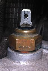
old sending unit was bad. 10 ohm resistance at 50* explains the constant gauge peg i had with the old sending unit. now for my random gauge spikes
i took the cluster back out. with it sill hooked up i was able to re-create random spikes by pressing on the laminated circuit near the temp gauge
took it out and although there was a slight amount of de-lamination in the corner the copper seems all intact and the only traces the de-lamination covered was ground past the temp gauge and and positive for the dash lights.
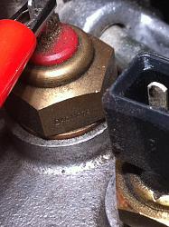
i had noticed some perforation the the copper trace on the ground of the gauge last time but shifted the washer to grab some fresh copper

what i did not notice last time is below that was a nut, so where its perforated is where the contact of the nut is from the bottom side so even though i shifted the washer the contact point is still the same so i added a small washer on top of the bottom nut under the laminated circuit to give more contact surface

added a grounding wire on top

found a suitable ground under the dash and ran a wire up to the cluster

i can no longer re-create the spikes of the gauge the way that i could before. so we will give it a few days before i call that fixed
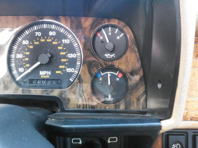
the gauge sit reads right about the top line of normal without some resistance added between the sender and the plug
update:
i wanted to get that old pot outta there so i would know if i had any more jumping of the gauge or anything like that i would know it was not the cause. and the pot was way to big to try to dial the gauge in just right a very slight adjustment of the pot would cause a big swing of the gauge. plus the pot was dirty (bad spots in the swipe the reason it was in the junk box to start with) so i first threw a 10 ohm resistor between the wire and the gauge and it put me just a touch above the n at normal operating temperature so i grabbed a 5 ohm and added it in series and it put me just a touch below the N and as my thermometer was showing me at 176* i figured that was just about right so i made up a little harness with the two resistors soldered into it.

gauge reading with my 15 ohm harness installed at 176*F
mine never gets up to 190 it seems to run between 170-180
old sending unit was bad. 10 ohm resistance at 50* explains the constant gauge peg i had with the old sending unit. now for my random gauge spikes
i took the cluster back out. with it sill hooked up i was able to re-create random spikes by pressing on the laminated circuit near the temp gauge
took it out and although there was a slight amount of de-lamination in the corner the copper seems all intact and the only traces the de-lamination covered was ground past the temp gauge and and positive for the dash lights.
i had noticed some perforation the the copper trace on the ground of the gauge last time but shifted the washer to grab some fresh copper
what i did not notice last time is below that was a nut, so where its perforated is where the contact of the nut is from the bottom side so even though i shifted the washer the contact point is still the same so i added a small washer on top of the bottom nut under the laminated circuit to give more contact surface
added a grounding wire on top
found a suitable ground under the dash and ran a wire up to the cluster
i can no longer re-create the spikes of the gauge the way that i could before. so we will give it a few days before i call that fixed
the gauge sit reads right about the top line of normal without some resistance added between the sender and the plug
update:
i wanted to get that old pot outta there so i would know if i had any more jumping of the gauge or anything like that i would know it was not the cause. and the pot was way to big to try to dial the gauge in just right a very slight adjustment of the pot would cause a big swing of the gauge. plus the pot was dirty (bad spots in the swipe the reason it was in the junk box to start with) so i first threw a 10 ohm resistor between the wire and the gauge and it put me just a touch above the n at normal operating temperature so i grabbed a 5 ohm and added it in series and it put me just a touch below the N and as my thermometer was showing me at 176* i figured that was just about right so i made up a little harness with the two resistors soldered into it.
gauge reading with my 15 ohm harness installed at 176*F
mine never gets up to 190 it seems to run between 170-180
Last edited by Ezrider; 03-12-2014 at 04:54 PM.
The following users liked this post:
sthames42 (03-16-2014)
#43
03-12-2014, 04:44 PM
INFO THANKS TO AllanG
This is the temp gauge on my XJS at a measured 190F

95 XJ6 with DAC 2583 (which is an Elmwood 81EL074 sensor. Elmwood are out of business) FEED voltage = 9.22v with engine running which I found odd.
94 XJS with DAC 11079 (B+ FEED VOLTAGE 14.22v)
DAC2583 | DAC11079
68F = 865 Ohms | 67F = 1370 Ohms
81F = 635 Ohms | 78F = 1003 Ohms
94F = 465 Ohms | 94F = 665 Ohms
104F = 388 Ohms | 104F = 529 Ohms
133F = 222 Ohms | 130F = 222 Ohms
158F = 143 Ohms | 160F = 150 Ohms
180F = 100 Ohms | 180F = 125 Ohms
190F = 90 Ohms | 190F = 100 Ohms
I hope you don't mind that i re-arranged some of the info from your post just to make it easier to reference without scrolling as much
This is the temp gauge on my XJS at a measured 190F
95 XJ6 with DAC 2583 (which is an Elmwood 81EL074 sensor. Elmwood are out of business) FEED voltage = 9.22v with engine running which I found odd.
94 XJS with DAC 11079 (B+ FEED VOLTAGE 14.22v)
DAC2583 | DAC11079
68F = 865 Ohms | 67F = 1370 Ohms
81F = 635 Ohms | 78F = 1003 Ohms
94F = 465 Ohms | 94F = 665 Ohms
104F = 388 Ohms | 104F = 529 Ohms
133F = 222 Ohms | 130F = 222 Ohms
158F = 143 Ohms | 160F = 150 Ohms
180F = 100 Ohms | 180F = 125 Ohms
190F = 90 Ohms | 190F = 100 Ohms
I hope you don't mind that i re-arranged some of the info from your post just to make it easier to reference without scrolling as much
Last edited by Ezrider; 03-12-2014 at 04:46 PM.
#44
03-13-2014, 09:24 AM
Glad the info was helpful and hope your problem is solved

#45
03-13-2014, 11:16 AM
Allan, I'm confused on the FEED voltage. I take it this is not in reference to the hot lead going to the gauge? According to the Elec Guide this is +12v from the ignition and that is what I've been using to test on the bench.
Is the sender not simply a thermistor that alters the GROUND resistance? If so, how does FEED voltage relate to it?
Thanks so much for providing the resistance levels.
BTW, if I sound like a complete novice it's because I am.
Is the sender not simply a thermistor that alters the GROUND resistance? If so, how does FEED voltage relate to it?
Thanks so much for providing the resistance levels.
BTW, if I sound like a complete novice it's because I am.
#46
03-13-2014, 12:23 PM
Allan, I'm confused on the FEED voltage. I take it this is not in reference to the hot lead going to the gauge? According to the Elec Guide this is +12v from the ignition and that is what I've been using to test on the bench.
Is the sender not simply a thermistor that alters the GROUND resistance? If so, how does FEED voltage relate to it?
Is the sender not simply a thermistor that alters the GROUND resistance? If so, how does FEED voltage relate to it?
And yes the sensor does just alter resistance as a function of temperature. But sensors also have a dissipation factor that can change performance based on the power applied. I noticed this when I measured the resistance with the engine off (12.7v) and saw that it changed as soon as I cranked the engine.
I'm not sure if it's a factor in this case but I just found it odd that the feed voltage on my XJ6 was 9.22v
#47
03-16-2014, 11:27 AM
Ok, first I want to say you were right, Allan, right from the beginning. My problem was not the sender and not the gauge. Just like you EZ, my problem appears to have been connectivity. When I bench tested both the original gauge and the used one I just bought, with the original sender, I got perfect readings. I put the instrument pack back together and did a careful check of all connections and tested again with the gauge in the pack and got perfect readings. Put the pack back in the car, and the original sender, and the gauge works great! So clearly this was a ground connectivity issue. While I may decide to add an additional ground in the future, it appears I don't need one right now.
Afterwards, I tested the replacement sender on the bench with the other gauge. Boiling water pegged the needle at H. Needle was at N when the temp was about 85F. Now I understand why so many people were talking about putting a resistor inline after replacing the sender. I never made the connection before.
I want to stress here, for anyone else that hits this problem, when I put the instrument pack back together, I carefully tested the connectivity between plug connections and terminals in the flexible circuit. By this, I mean connecting the ohmmeter to the terminal posts--not the screws--and checking the readings for connectivity to other posts in the circuit as well as the plug connection tabs. I mention this only because I noticed much black buildup on some of the connections and assume this could have interfered with connectivity. While you may indeed have needed an extra ground, EZ, which is how many besides you have solved this problem, I have to wonder if the problem may have been simple connectivity in the flexible circuit. I still don't know what my original problem was. Only that, in the end, I cleaned all the connections, posts, and screws, carefully tested for connectivity, replaced the pack, and voila!
My tach is again not working but this happens whenever I take out the instrument pack. So far it has always started working again within a few days. I'm going to give it a week before I take out the pack again. From looking at the flexible circuit, I can't tell where the tach is grounded. I can see B+ and coil but the ground is unclear. I'm assuming the ground may be internal to the pack. If so, I'll have to take it apart again and test the gauge by grounding the body and jumping to the coil. Never done that so I hope I don't have to.
But the big problem is solved. $70 it turns out I didn't need to spend but the lessons were worth it and probably a bargain after all.
Thanks again to everyone.
#48
03-18-2014, 05:31 PM
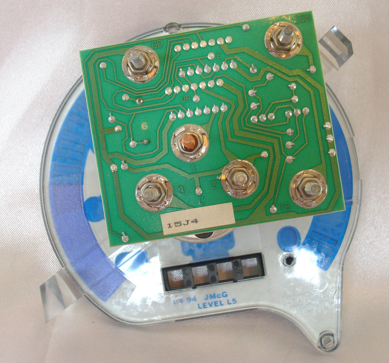
Ok, I'm still having a problem with the tach not working. Going to give it till the end of the week before taking the pack out again. As I said, I'm having trouble figuring out how the tach is grounded. Here is a pic of the flex circuit:

I would like to test the tach while still in the instrument pack by applying B+ and GND from my bench DC power supply and shorting to the COIL. Can anyone tell me how the tach is grounded? I cannot tell from looking at the back of the pack.
I would like to test the tach while still in the instrument pack by applying B+ and GND from my bench DC power supply and shorting to the COIL. Can anyone tell me how the tach is grounded? I cannot tell from looking at the back of the pack.
#50
03-19-2014, 12:06 PM
I managed to find a picture of the back of the tachometer which clearly shows the ground connection to be what I thought was a connection to a signal light but appears to actually be a ground for the signal lights which wraps around back to P1 of the 14-way just as you indicated.
I am going to take out the instrument pack and test the tach by apply B+ and GND directly to the terminal screws and jumping to the coil. I assume this will tell me if my problem is the tach. If it works, I again have a ground problem in the flexible circuit.
If you see any flaw in my logic or procedure, please let me know.
#51
03-19-2014, 03:57 PM
I am going to take out the instrument pack and test the tach by apply B+ and GND directly to the terminal screws and jumping to the coil. I assume this will tell me if my problem is the tach. If it works, I again have a ground problem in the flexible circuit.
If you see any flaw in my logic or procedure, please let me know.
If you see any flaw in my logic or procedure, please let me know.
A couple of continuity checks I would do if you haven't already. They are less likely to cause issues than applying power directly to the PCB.
1. Check the continuity of the wire from the coil to the instrument pack.
2. If that's ok, check the continuity of the track on the PCB from Pin1 to the tach ground connection.
You seem to have power and gnd to the PCB as your other instruments/warning lights are working so my guess is a wiring issuer an internal issue with the tach.

Thread
Thread Starter
Forum
Replies
Last Post
BrentGardner
XJ XJ6 / XJ8 / XJR ( X350 & X358 )
28
04-26-2024 03:08 AM
FS[SouthEast]: GenRad GDS-510 scan tool
johnnie ryall
PRIVATE For Sale / Trade or Buy Classifieds
6
10-19-2015 09:44 PM
msdg137
XK8 / XKR ( X100 )
7
09-16-2015 06:24 AM
Currently Active Users Viewing This Thread: 1 (0 members and 1 guests)