
Ever see these intakes
#21
 03-11-2017, 09:02 AM


Veteran Member
Thanks Warren. So what do you do about the guide, grind away the whole lot poking into the manifold, thick piece and thin piece I can see?
If so, doesn't that reduce the guide length and if it does, does it matter that there is more of the valve stem exposed, and less guide to support the stem?
Greg
If so, doesn't that reduce the guide length and if it does, does it matter that there is more of the valve stem exposed, and less guide to support the stem?
Greg
The following users liked this post:
ronbros (03-11-2017)
#22
03-11-2017, 01:49 PM


Veteran Member
Join Date: Jul 2010
Location: Austin tx and Daytona FL.
Posts: 7,362
Received 1,236 Likes
on
943 Posts
I am referring to the intake port from the valve to the manifold flange. An ideal intake port is a ventui, so it does need to narrow, this increases the velocity of the air, but it needs to be sized correctly for the valve train, too big and it will reduce the force of air into the cylinders at low to mid rpm, too small and it will reduce air at all rpm.
A duct will only flow as much air as the smallest cross section will pass, (ie the valve guide area) so making the intake manifold larger will have NO effect on how much air we can get into the cylinder.
The problem with the V12 is the port at the guide is a little too narrow at 29mm and has a great big valve guide blocking a portion of the passage (see photo). So we need to open this area out BUT NOT TOO MUCH. From calculations 31mm (754mm�) is a good port diameter for the narrow bit with stock valve train (ie valve diameter & lift also = valve curtain area).
I hope I have answered your question.

i been thinkin about this subject! LOL.
OK, is the inlet port on the pre HE the same as the HE head???
if so then the reason for the socalled venturi at the guide area for the pre-he was to try to induce some swirl of air flowing into the cylinder bore?
but does not contribute much for homogenus tumble and mixing of mixture.
if the HE uses it for same theory, that means that some swirl will allready be present at about 50% lift, then the May chamber shape will really have some serious swirl effect! but not for cylinder filling for swirl and tumble in the bore!
now on to what i did with my pre-he inlet ports and valve bowls, at the pinch point(venturi)! not sayin its perfect, but only used common sense port/flow ideas, 22yrs ago there was NO internet(worth ash$t). and getting any knowledge out of England was a joke!
realized that pre-he inlet and exhaust valves were recessed about .050 thou. deep into head surface, so i milled/planed the head surface down to the valve seat level, NOW that put both my valves at equal hite and NO shrouding!
so when valve starts opening air flows quickly, and fill is much greater window the full length of inlet phase/time!
i removed guides(standard operation), opened port and bowls/venturi about 1/16" all the way thru,tapered the guides, polished/shaped things like any common cutter marks, blending all the way thru.
thats standard procedure on hi-performance heads! been doin it since 1950s.
for the manifolds an plenums, i sent to company in NY , for what is called EXTRUDE HONING, thet took out all the internal humps,bumps and injector casting flash ,and opened plenum and runners about 1/8". a subject A.Scott says not needed!
port matching was a PITA getting it as close as i could.
anyway does any of this help,DONNO, but if i had it to do over i just stroke the son of a B$$tch to 84MM , balance it! and be done with it.
lest you may forget a piston moving down on inlet stroke,with 84MM sucks alot more AIR than the teeny/wheeny 2 3/4" stroke 5.3L at the SAME RPM!
also you are trying to fill the cylinder, the chamber only is to direct the air in! along with some semblence of combustion control! now thats a good one,LOL.
BUT YES, im getting anxious for WARRJON to show his build up and see what results he comes up with,, torque and HP, dynod! just his 6.0L stroke is a big torque producer!
#23
03-11-2017, 03:11 PM

hey guy, thats basicly what is said at post #4.
long runners, as close to length that would fit under hood, large plenum volume, TB at front.
and factory did the best they could with money available!
and remember this is not a race car engine, it was designed for smooth power delivery, and economy! and a V12 will never ever be an MPG king.
long runners, as close to length that would fit under hood, large plenum volume, TB at front.
and factory did the best they could with money available!
and remember this is not a race car engine, it was designed for smooth power delivery, and economy! and a V12 will never ever be an MPG king.
hey guy, I was just trying to state that even in the new manifold design, seen in the picture, they still had to put baffles inside the plenum to equalize the air flow down each runner... and I must
apologize for restating what you wrote in post #4.

The following users liked this post:
ronbros (03-11-2017)
#24
03-11-2017, 04:13 PM
Veteran Member
Join Date: Jul 2010
Location: Austin tx and Daytona FL.
Posts: 7,362
Received 1,236 Likes
on
943 Posts
Thanks Warren. So what do you do about the guide, grind away the whole lot poking into the manifold, thick piece and thin piece I can see?
If so, doesn't that reduce the guide length and if it does, does it matter that there is more of the valve stem exposed, and less guide to support the stem?
Greg
If so, doesn't that reduce the guide length and if it does, does it matter that there is more of the valve stem exposed, and less guide to support the stem?
Greg
hi greg, actually if you reduce the length of guide you let more air thru the pinch point along with necking down the stem area between guide and valve underhead,all is good!
some race engines put in all new guides with a smaller stem diameter, just to increase the volume of that port to valve bowl area, along with making the valves much lighter in weight!
of course using a hi quality material, titainium, super steels, and some steels i'v never heard of, another is Sodium filled are lighter and tougher!
i have never seen,in person, a Gp44 or TWR cylinder head but i know they are much bigger ports and valves.
but with big cubic inches you need more air flow!
did i mention my valves now are .050 thou. deeper into the cylinder bore, give thought how much more air can enter cylinder, only restriction is the bore side,in one area.
Last edited by ronbros; 03-12-2017 at 12:16 PM.
#25
03-11-2017, 04:14 PM
Veteran Member
Thanks Warren. So what do you do about the guide, grind away the whole lot poking into the manifold, thick piece and thin piece I can see?
If so, doesn't that reduce the guide length and if it does, does it matter that there is more of the valve stem exposed, and less guide to support the stem?
Greg
If so, doesn't that reduce the guide length and if it does, does it matter that there is more of the valve stem exposed, and less guide to support the stem?
Greg
Remove all of the aluminium boss but do not remove the any of the valve guide. The port can be widened and the roof raised at the guide to increase the cross sectional area to 754mm�. The valve guide diameter is 12.75mm and sticks into the port about 8.7mm giving an area of approx 111mm�.
So port diameter should be ((110 + 754) / 3.14) sqrt x 2 = 33mm diameter
Any bigger than 33mm at the guide will IMO hurt power through the whole RPM range without valve train modifications, ie larger valve higher lift.
All of this also assumes a good 3 angle valve job first.
The following 4 users liked this post by warrjon:
#26
03-11-2017, 04:19 PM
Veteran Member
Norm has finished the bottom end but I'm the hold up with the heads.
I have bought new vacuum motors for my flowbench as I need to modify it from a leaf blower.
#27
03-11-2017, 07:29 PM
Veteran Member
In my above post the 33mm diameter at the valve guide is a best guess based on some know ratios and a good place to start.
The port needs to be flow tested to verify my theory.
I am building a new flowbench and will flow test my heads before I remove ANY material from the valve guide area. I will be testing for flow at max lift and beyond (9.5mm to 10.5mm). The reason for this is if the valve continues to flow more air beyond maximum lift then the port is too big for the valve train. So either increase valve diameter/lift or reduce port size. If the port is too small then the flow will stagnate at some lift before maximum, it will then be gradually opening the port and testing until I get full flow at max lift.
I will fill the intake port entry with epoxy to bring it back to 33mm ID which is what the intake runners are.
I will document everything I do so anyone wanting to modify a set of HE heads has a good starting point.
As I am using the stock valve train for cost reasons, so lets see how it can be optimised for best power / torque.
Last edited by warrjon; 03-11-2017 at 07:32 PM.
The following 4 users liked this post by warrjon:
#28
11-08-2017, 02:33 PM

Now days this sort of thing is made in China or Thailand for peanuts. Look at the price of aluminium radiators for example.
http://www.made-in-china.com/product...st_Header.html
http://www.made-in-china.com/product...st_Header.html
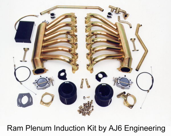
Aj6 eng. Ram Plenum tuned length induction system kit for the V12 produced during 1986-92. This beefed up a standard engine by nearly 70 b.h.p. but was too expensive to manufacture. Close to 600 b.h.p. was possible from a race engine. We first started producing our large throttles for this application
no longer available... sad... every one likes 70 more HP....
maybe we can talk him out of the Drawings for this design...
no longer available... sad... every one likes 70 more HP....
maybe we can talk him out of the Drawings for this design...
Last edited by LongJohn; 11-08-2017 at 02:36 PM.
#31
11-09-2017, 01:17 AM
Veteran Member
This:
V12 ARCHIVES / AJ6 Engineering
And I agree, we should all ask Roger to restart production!
Greg
V12 ARCHIVES / AJ6 Engineering
And I agree, we should all ask Roger to restart production!
Greg
#32
11-09-2017, 03:17 AM
Veteran Member
This:
V12 ARCHIVES / AJ6 Engineering
And I agree, we should all ask Roger to restart production!
Greg
V12 ARCHIVES / AJ6 Engineering
And I agree, we should all ask Roger to restart production!
Greg
The following users liked this post:
Greg in France (11-09-2017)
#33
11-09-2017, 03:31 AM
Veteran Member
Thanks Warren. So what do you do about the guide, grind away the whole lot poking into the manifold, thick piece and thin piece I can see?
If so, doesn't that reduce the guide length and if it does, does it matter that there is more of the valve stem exposed, and less guide to support the stem?
Greg
If so, doesn't that reduce the guide length and if it does, does it matter that there is more of the valve stem exposed, and less guide to support the stem?
Greg
Exhaust valve guide was cut back to the guide boss, intake guide was left untouched, guide boss was cut back to aide flow.
The following 2 users liked this post by warrjon:
Greg in France (11-09-2017),
xjsv12 (11-09-2017)
#34
11-09-2017, 06:35 AM
Production in the UK would be very expensive and that�s the reason why Roger stopped making them if the posts above are correct.
Labour in the more modern factories in China is productive and 10% of the cost of Europe. All the tubes and bends required are easily and cheaply available. Look at the prices for Chevy extractors I sent in the link in my post above.
The jigs for these intake manifolds and extractors need to be sent to China.
This:
V12 ARCHIVES / AJ6 Engineering
And I agree, we should all ask Roger to restart production!
Greg
V12 ARCHIVES / AJ6 Engineering
And I agree, we should all ask Roger to restart production!
Greg
#37
11-10-2017, 01:41 AM
Veteran Member

Thread
Thread Starter
Forum
Replies
Last Post
Currently Active Users Viewing This Thread: 1 (0 members and 1 guests)