When you click on links to various merchants on this site and make a purchase, this can result in this site earning a commission. Affiliate programs and affiliations include, but are not limited to, the eBay Partner Network.
That steel ring is welded in.To remove the large shaft that goes thru the lower bushings, either the front suspension has to come out of the car, or the back end of the front suspension has to be lowered by unbolting the rear mounts and rotating the suspension down from the front mounts. The engine also has to be disconnected from its mounts and supported with a crossbar across the engine bay. Otherwise the shaft won't clear the engine when they are driven out to the rear.
That steel ring is welded in.To remove the large shaft that goes thru the lower bushings, either the front suspension has to come out of the car, or the back end of the front suspension has to be lowered by unbolting the rear mounts and rotating the suspension down from the front mounts. The engine also has to be disconnected from its mounts and supported with a crossbar across the engine bay. Otherwise the shaft won't clear the engine when they are driven out to the rear.
Maybe I should’ve mentioned mine is a V8 swap car. The only thing in the way of the lower control arm bolt is the inner tie rod as far as I can see. All the stuff you mention - is that just to make room for the bolt or is there another purpose for all that?
The rear end of the shaft has a hexagon end on it, rather like a thin bolt, but this does not undo, and do NOT try to turn the shaft using this end.. The shaft may well come out without any work on the subframe, if so lucky you, compared with your V12 bretheren. The shaft MAY be very tight in the subframe, or may knock out easily, depending upon the amount of rusting in that has happened. If it is stuck, the only solution is to whack the forward end with an FBH, many times. But as your spring pans looked in great shape, you may well be OK.
If you do remove the pin and renew the bushes, you MUST use metalastik brand only, (available from David Manners in the UK, if not elsewhere) anything else just gives up in weeks.
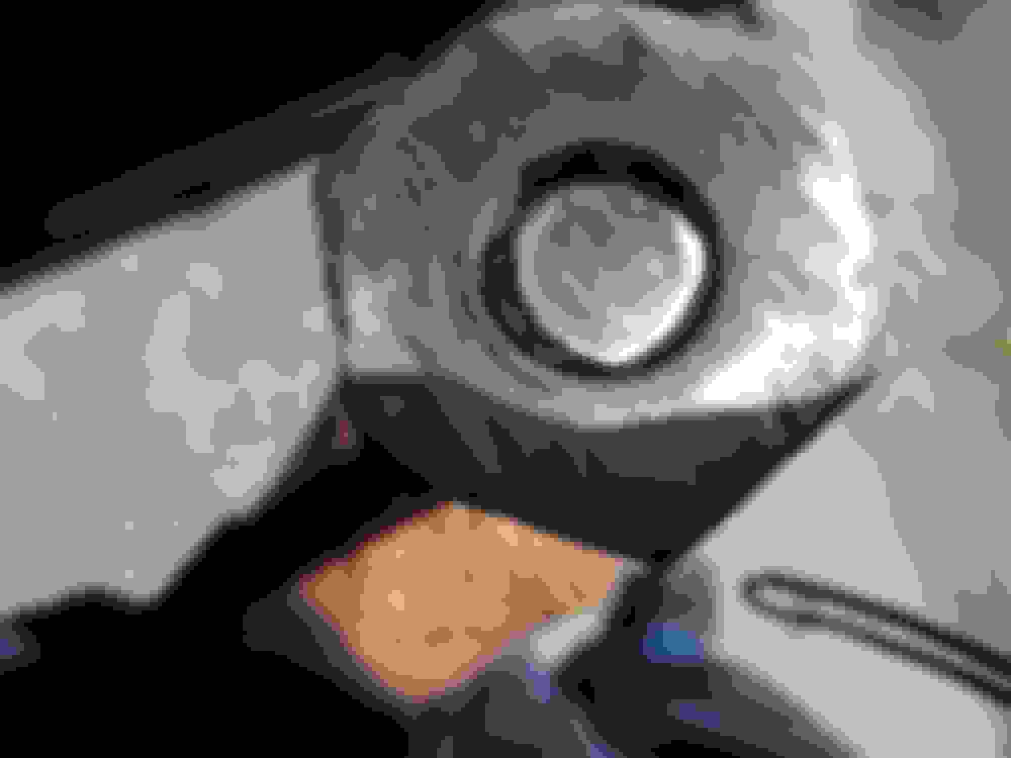
Also, check the raer end of the pin, as the hex end on it can come loose, it is a good plan to weld it on if it shows any sign of not being strongly attached, to be sure. As in this photo:
What shape are the lower wishbone bushes in? Post a photo, as it may not be necessary to change them.
Last edited by Greg in France; 02-19-2022 at 12:47 AM.
The rear end of the shaft has a hexagon end on it, rather like a thin bolt, but this does not undo, and do NOT try to turn the shaft using this end.. The shaft may well come out without any work on the subframe, if so lucky you, compared with your V12 bretheren. The shaft MAY be very tight in the subframe, or may knock out easily, depending upon the amount of rusting in that has happened. If it is stuck, the only solution is to whack the forward end with an FBH, many times. But as your spring pans looked in great shape, you may well be OK.
If you do remove the pin and renew the bushes, you MUST use metalastik brand only, (available from David Manners in the UK, if not elsewhere) anything else just gives up in weeks.
Also, check the raer end of the pin, as the hex end on it can come loose, it is a good plan to weld it on if it shows any sign of not being strongly attached, to be sure. As in this photo:
What shape are the lower wishbone bushes in? Post a photo, as it may not be necessary to change them.
Thanks as always Greg. I’ll try to grab a photo later today. These are the lower control arm bushings I purchased; I knew better than to go poly but these aren’t metalastik either: https://www.autohausaz.com/pn/C008673
Honestly doesn’t seem worth it then, and I’m working with the JCNA’s loaner timeframe anyways. I’ll still be doing the uppers and the sway bar bushings and sway bar end link bushings.
Ok I have both front springs off, so now I'm doing the sway bar bushings and end link bushings.
What's the best way to reinstall the sway bar bushings? The mounting holes in the body are in-line with each other but the bushing carrier holes are offset to twist the bushing forward so it's pointed slightly towards the front of the car. Best as I can tell there's two options: put the bushing in the bushing carrier, connect one of the carrier bolts to the body (loosely, I know nothing is supposed to be torqued down until the suspension is loaded), and then try to force/pry the other side of the carrier until the remaining carrier bolt hole lines up with the body bolt hole.
Or attach both bolts to the carrier and body without the bushing installed, and then try to slide the bushing into position.
I tried both methods yesterday, and both seem very difficult. The first option seems like the easier of the two, but I don't know how I can "pry" the mount enough to line up the second bolt hole. Everything is thoroughly greased up as well. And obviously the car is still in the air due to the spring job in progress. Any tips on how to tackle this?
Need some help understanding how exactly the two alignment rods or used upon spring installation. I think I know where they go but I don’t understand how they’re secured.
Here’s a video describing my question with visuals:
The spring pan bolts and nuts are 3/8ths UNF.
The guide rods screw into the wishbone, so the pan/spring combo is guided up them as you tighten the tool. Without them it would be impossible to align the pan holes with the threaded holes in the wishbone. Place one into one of the innermost holes on the wisdhbone and theb other on the middle hole on the opposite side. Once the pan is compressed up into position, screw in the other bolts to secure it, then unscrew the rods and replace them with their bolts.
I cannot follow your post no 30, post a photo of the problem if you are still unsure what to do.
Mr Anderson if you watch this (last few mins) you will see the guide pins as well as the correct use of the tool. Note they refer to the tool ad JD6F which as said before was the previous version--the 'G' version saw the addition of the collar that caused you so much concern.
Please watch!!!!!!!!!
The spring pan bolts and nuts are 3/8ths UNF.
The guide rods screw into the wishbone, so the pan/spring combo is guided up them as you tighten the tool. Without them it would be impossible to align the pan holes with the threaded holes in the wishbone. Place one into one of the innermost holes on the wisdhbone and theb other on the middle hole on the opposite side. Once the pan is compressed up into position, screw in the other bolts to secure it, then unscrew the rods and replace them with their bolts.
I cannot follow your post no 30, post a photo of the problem if you are still unsure what to do.
Got it, that makes much more sense - I could've sworn I read in an old thread that the locating pins were supposed to go through the two outermost holes; I must've misread something.
I figured out the sway bar bushings, just had to apply more force to line up the bushing carrier holes with the body holes.
Mr Anderson if you watch this (last few mins) you will see the guide pins as well as the correct use of the tool. Note they refer to the tool ad JD6F which as said before was the previous version--the 'G' version saw the addition of the collar that caused you so much concern.
Please watch!!!!!!!!! https://www.youtube.com/watch?v=tWYCJ6aGD0M&t=5s
Thanks; love the old training video. I'll have to watch some of the others on your YouTube page.
The spring pan bolts and nuts are 3/8ths UNF.
The guide rods screw into the wishbone, so the pan/spring combo is guided up them as you tighten the tool. Without them it would be impossible to align the pan holes with the threaded holes in the wishbone. Place one into one of the innermost holes on the wisdhbone and theb other on the middle hole on the opposite side. Once the pan is compressed up into position, screw in the other bolts to secure it, then unscrew the rods and replace them with their bolts.
I cannot follow your post no 30, post a photo of the problem if you are still unsure what to do.
Hi Greg, I’m trying to install the springs and frankly I just don’t understand how these locating pins work. I completely understand how they’re supposed to work on paper, but I can’t get the pan holes to line up with the locating pins.
I tried raising the lower control arm with a floor jack so its angle relative to the floor matches the spring pan’s angle relative to the floor, but the issue with that is the spring then has to be compressed much more before it reaches the locating pins.
The only other solution I can think of is combining the alternative “threaded rod” spring method with the legitimate Jag tool - that way I can start guiding the pan much sooner. The locating pins are only a few inches long, but the threaded rods are more like a foot.
Go back and look at the training video--you have one of the pins in the wrong position. These tools have been loaned out for years with no issues. Not sure what is going on here. You were offered a phone number to call for help.
Yes, the spring seats are at different angles. This is how it's *Supposed* to be, don't let that confuse you.
Take a look at these images and see for yourself how to install your springs. Admittedly, I didn't have the "Proper Tool" as you do, and had to do it the Shadetree way, but the principle is Exactly the Same! https://www.jaguarforums.com/forum/x...3/#post2369020
Notice the Golden Unthreaded Guide bolt position. As Coventry mentions, yours are not correct. Mine may not match the training video positions either, but this is how I got it done--Twice!
(';')
Go back and look at the training video--you have one of the pins in the wrong position. These tools have been loaned out for years with no issues. Not sure what is going on here. You were offered a phone number to call for help.
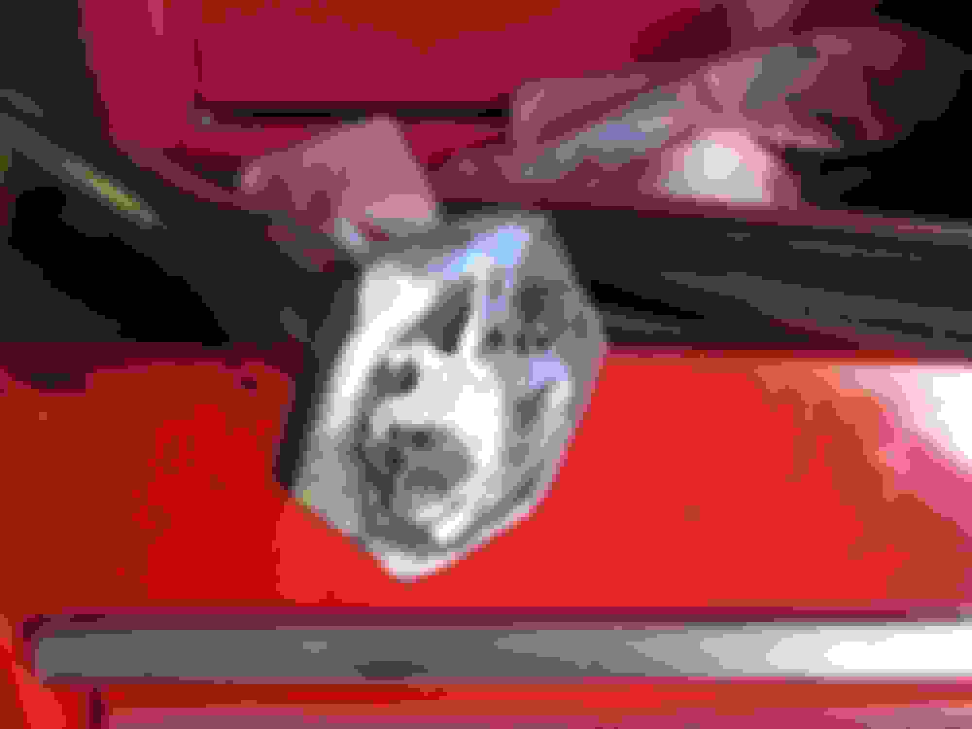
I must really be missing something then. In the video I grabbed this image:
It appears to me that the one on the right is in the innermost hole. That's what I did with mine.
The camera is at an angle, but it appears to me that the other rod is in the middle hole on the other side. That's also what I did with mine.
How are you interpreting this picture and/or my video?
Yes, the spring seats are at different angles. This is how it's *Supposed* to be, don't let that confuse you.
Take a look at these images and see for yourself how to install your springs. Admittedly, I didn't have the "Proper Tool" as you do, and had to do it the Shadetree way, but the principle is Exactly the Same! https://www.jaguarforums.com/forum/x...3/#post2369020
Notice the Golden Unthreaded Guide bolt position. As Coventry mentions, yours are not correct. Mine may not match the training video positions either, but this is how I got it done--Twice!
(';')
Thanks - in your photo it looks like both of your unthreaded guide bolts wen through the middle holes, which is totally doable. It's getting one of the guide bolts through one of the innermost holes that frankly seems impossible.

 02-18-2022, 04:33 PM