When you click on links to various merchants on this site and make a purchase, this can result in this site earning a commission. Affiliate programs and affiliations include, but are not limited to, the eBay Partner Network.
They look like a phillips head (screw) but they are not tapered like a phillips head, rather they are flat bottom (or at least I can figure out.
So if you try and remove them with a normal screw driver, doesn't always work
Bonnet catch mechanism with Pozi Drive bolt
M6 Allan thread installed (complete with bike brake cable)
Hi... I would like to know what you guys are talking about with the PoziDrives... New to me. Anyone have a photo of one and where in the car? I'd be grateful
Pozis are the exact type of cross-headed screws used throughout the XJS. They look like Philips cross-heads, but the profile is quite different and using a Philips driver on a Pozi-headed screw will not work.
Most of the pozidrives are either M6 (mostly) or M8. I have been putting Allan screws in
You can buy correct tooling bits for the pozi drives though
Cheers
Steve
Pozi-headed threaded bolts (as opposed to pozi-headed self tapping screws which are also used throughout the XJS) in the XJS usually, if not always on pre-facelifts, have UNF threads on them.
The only issues I have had in replacing the Pozi bolts with the Allan bolts is the car front seat rails to the chassis (near the centre consul). These don't seem to be metric or imperial, so the original stud went back in that spot. Mind you, I didn't want to stuff those threads up, so I didn't try too hard
Cheers
||Pozi-headed threaded bolts (as opposed to pozi-headed self tapping screws which are also used throughout the XJS) in the XJS usually, if not always on pre-facelifts, have UNF threads on them"
It is interesting, when I first started down the line - I purchased both imperial and metric. The metric seemed to be the better fit (the imperial did not fit at all). On quite a few occasions, I have removed the Allan bolts and reinstated the Pozi drive bolts, and then changed them out again later. There is no noticeable different between the 2 (don't seem to be damaging the threads).
I got the car to start!!
Added some fresh gas, reconnected the battery, turned the key and “Click”. The starter relay went click but the starter didn’t turn. I turned the key off, then back to on and I couldn’t hear the fuel pump running. So I pulled the starter relay, the main relay, and the fuel relay and took them inside to work on. With a 9V battery and an ohm netter I was able to check that all three were working. I cleaned the contacts and put them back in. This time the fuel pump came on when I turned the key. I ran it a few more times and then cranked the engine, it turned but didn’t start. A few more times and it ran very roughly at idle, but smoothed out with a bit of throttle. Encouraged, I decided to check the butterfly valves and idle control valves. The butterfly valves were very tightly closed with the throttle rods off, and they were pulling they valves even tighter. With this all adjusted properly so that the butterfly valves have a 0.002” gap, the car idled much better at about 650 rpm. It was still a little rough, maybe timing, maybe something else, but it was really loud! I turned it off and out my tools away, then started it up again. I’m amazed at how quickly it catches when you turn the key, but this time it ran badly. Worse than when I first got it to run with lots of blue smoke out the back and some coming up the sides of the engine.
Then I realised what I’d done. When I changed the oil a few weeks ago I hadn’t changed the filter, because I used cheap oil and have been planning on changing it again once the car was running. But I put the full amount of oil in, so now it has a quart too much or so. The level on the dip stick is 1/4” over full. So I’ll need to fix this. As to why it’s so loud? Someone either started to remove the exhaust of didn’t finish putting it back on. All four down pipe flanges have nuts on them, but the flanges are at least 1/2” away from the manifold, so there’s a huge gap! I suppose I should really pull it apart and fit new gaskets, but I’m going to try just tightening them up first, it should help a lot.
You talking about the manifold to catalyst/downpipe joint? I used 1/4 drive socket, very long extensions, one of those bendy joints, and a impact gun. You’re not supposed to use an impact gun on regular sockets but what are ya gonna do? Breaking the nut free with bendy joints in the extensions is difficult so that why I use impact gun... once they’re moving you can do it by hand no problem. Taking off the heat shields on the steering rack can help too. It’s all doable.
Made a bit more progress with the car. I decided to start working on the front suspension. All the bushings look original and quite worn, so they're all getting replaced. I'm going to have a shop replace the lower control arm inside bushings because I don't have the ability to unload the spring safely, but everything else I can do myself. The top wishbone was pretty easy. With the car supported properly and the wheel off, I put the jack under the lower ball joint and lifted until the upper bumpstops came off their rest. Then I undid the nut in the upper ball joint and lowered the assembly off the jack. With lots of help from the spring and a little from a crowbar, the upper ball joint popped out of its mount pretty easily. From there disassembling the upper wishbone and renewing all the bushing, ball joint and locknuts was very straightforward. The lower ball joint put up much more of a fight. First off, it's harder to get to, secondarily, I no longer have the spring to help me. Eventually, I removed the caliper and pulled the disk towards me to have maximum access. I removed the bottom cover on the ball joint and used a gear puller to separate the ball from the lower wishbone. This seemed like it wasn't doing anything until it suddenly popped out. Both the upper and lower ball joints were replaced with sealed new ones. The original lowers are rebuildable, but that seemed like an unnecessary amount of work, especially since the sealed ones last longer. Next I tackled the brakes. The pad had plenty of life left, but the disk was down to its minimum thickness. It wasn't undersized, but while I was doing all this work it seemed like a good time to replace it. The disks are attached to the inside of the hub, for the sole purpose of making it extra fun to change them. I undid the bolts holding the disk to the hub from the back. I'm so glad I bought an impact driver when I started this project, it makes things like that so easy. I pulled the hub off, dust cover, split pin, little crown thing that hold then pin to the nut, nut, washer. Then the hub itself. I put a flattened cardboard box underneath to catch any falling bearings, which was an excellent idea as the outside bearing immediately landed on the box. Much better than landing in gravel. The inside bearing came out fully assembled, which raises the question of were the rollers spinning or was the ring spinning? Apparently that can happen, but I didn't know that until after it was back together. I may need to revisit it. The new disk was fitted and torqued to the hub, then the hub was reinstalled. There's a rather complicated procedure for setting end float, or a much easier approximation. I went with the latter. While spinning the disk, torque to 25 ft lbs, then back off 1/6th of a turn. It seems to spin with the same level of slight resistance that I had before I disassembled it, so hopefully it will work. The caliper was next. All the seals (or are they just dust jackets?) on the pistons were torn, so I removed them, pulled out the pistons, removed the inner seals and cleaned out the caliper. There was some very light surface rust on one of the pistons, some very fine sandpaper cleaned it up quickly. New inner seals, new dust jackets, pistons back in, new pads, then back on the car. The hardest part was putting the bolts back in. They're hard to see and line up, but there are also several small shims that need to go between the caliper and the steering arm. Eventually I got it back together correctly I think. Finally, I fitted a new brake hose. The front brake fittings are some of the few metric fasteners on the car, just for fun. The inside end of the hose it fairly inaccessible, I can feel it but can't really see it. Eventually the nuts were undone, the old hose removed and the new one fitted. I still need to lock wire the caliper bolts and fit a new tierod end. Then the other side and the swaybar mounts and links.
Hi... I would like to know what you guys are talking about with the PoziDrives... New to me. Anyone have a photo of one and where in the car? I'd be grateful
JJJ
An cross-headed screw you see on the car will be a pozi, as opposed to a Philips. They look similar, but have different profiles and the screwdriver for one will not fit the other. The huge cross-headed screws that hold the engine bay bracers are pozi size 3 or 4s, but most screws on the car are pozi size 2s.
Made a bit more progress with the car. I decided to start working on the front suspension. All the bushings look original and quite worn, so they're all getting replaced. I'm going to have a shop replace the lower control arm inside bushings because I don't have the ability to unload the spring safely, but everything else I can do myself. The top wishbone was pretty easy. With the car supported properly and the wheel off, I put the jack under the lower ball joint and lifted until the upper bumpstops came off their rest. Then I undid the nut in the upper ball joint and lowered the assembly off the jack. With lots of help from the spring and a little from a crowbar, the upper ball joint popped out of its mount pretty easily. From there disassembling the upper wishbone and renewing all the bushing, ball joint and locknuts was very straightforward. The lower ball joint put up much more of a fight. First off, it's harder to get to, secondarily, I no longer have the spring to help me. Eventually, I removed the caliper and pulled the disk towards me to have maximum access. I removed the bottom cover on the ball joint and used a gear puller to separate the ball from the lower wishbone. This seemed like it wasn't doing anything until it suddenly popped out. Both the upper and lower ball joints were replaced with sealed new ones. The original lowers are rebuildable, but that seemed like an unnecessary amount of work, especially since the sealed ones last longer. Next I tackled the brakes. The pad had plenty of life left, but the disk was down to its minimum thickness. It wasn't undersized, but while I was doing all this work it seemed like a good time to replace it. The disks are attached to the inside of the hub, for the sole purpose of making it extra fun to change them. I undid the bolts holding the disk to the hub from the back. I'm so glad I bought an impact driver when I started this project, it makes things like that so easy. I pulled the hub off, dust cover, split pin, little crown thing that hold then pin to the nut, nut, washer. Then the hub itself. I put a flattened cardboard box underneath to catch any falling bearings, which was an excellent idea as the outside bearing immediately landed on the box. Much better than landing in gravel. The inside bearing came out fully assembled, which raises the question of were the rollers spinning or was the ring spinning? Apparently that can happen, but I didn't know that until after it was back together. I may need to revisit it. The new disk was fitted and torqued to the hub, then the hub was reinstalled. There's a rather complicated procedure for setting end float, or a much easier approximation. I went with the latter. While spinning the disk, torque to 25 ft lbs, then back off 1/6th of a turn. It seems to spin with the same level of slight resistance that I had before I disassembled it, so hopefully it will work. The caliper was next. All the seals (or are they just dust jackets?) on the pistons were torn, so I removed them, pulled out the pistons, removed the inner seals and cleaned out the caliper. There was some very light surface rust on one of the pistons, some very fine sandpaper cleaned it up quickly. New inner seals, new dust jackets, pistons back in, new pads, then back on the car. The hardest part was putting the bolts back in. They're hard to see and line up, but there are also several small shims that need to go between the caliper and the steering arm. Eventually I got it back together correctly I think. Finally, I fitted a new brake hose. The front brake fittings are some of the few metric fasteners on the car, just for fun. The inside end of the hose it fairly inaccessible, I can feel it but can't really see it. Eventually the nuts were undone, the old hose removed and the new one fitted. I still need to lock wire the caliper bolts and fit a new tierod end. Then the other side and the swaybar mounts and links.
Dude!!! You are the Man!
Good work and great descriptions! Really. Lol,,, like I was there myself (actually had a few chilling flashbacks haha)... Good stuff!
One thing I would say, and saves a lot O trouble, is one of those fairly inexpensive pinching ball joint poppers. Looks like a little claw with a 19mm bolt going thru the end to tighten down the pinching end... Jus say'n.
Oh, and careful. I could be wrong but I THINK that with both ball joints removed the ONLY thing holding the spring tension at that point is the lower shock bolt. A very little thing if you think about it. Again, jus say'n.
JJJ
An cross-headed screw you see on the car will be a pozi, as opposed to a Philips. They look similar, but have different profiles and the screwdriver for one will not fit the other. The huge cross-headed screws that hold the engine bay bracers are pozi size 3 or 4s, but most screws on the car are pozi size 2s.
Wow - that is good work.
Unlike JJJ I am completely lost.
I am planning to do this job one day and will save this info, thanks.
Did you change the----- I'm going to have a shop replace the lower control arm inside bushings because I don't have the ability to unload the spring safely, but everything else I can do myself.?
Dude!!! You are the Man!
Good work and great descriptions! Really. Lol,,, like I was there myself (actually had a few chilling flashbacks haha)... Good stuff!
One thing I would say, and saves a lot O trouble, is one of those fairly inexpensive pinching ball joint poppers. Looks like a little claw with a 19mm bolt going thru the end to tighten down the pinching end... Jus say'n.
Oh, and careful. I could be wrong but I THINK that with both ball joints removed the ONLY thing holding the spring tension at that point is the lower shock bolt. A very little thing if you think about it. Again, jus say'n.
Youĺre correct that the shock and inner bushings are all thatĺs holding the spring in, but this is the factory procedure. You canĺt get to the lower ball joint nut with the upper ball joint in position. Iĺm not sure if I could get a ball joint separator in there, itĺs really tight. And I already had a gear puller...
Does anyone have any tips for removing the sway bar mounts? I can put a wrench on them, but the bolt turns with the nut. I can see about half the bolt from above, and I do have a long extension, so I guess I’ll try that, unless anyone has a better idea?
Does anyone have any tips for removing the sway bar mounts? I can put a wrench on them, but the bolt turns with the nut. I can see about half the bolt from above, and I do have a long extension, so I guess I’ll try that, unless anyone has a better idea?
You can just get at the top of the bolt from above with a long socket extension and the airbox covers out of the way.
It’s been a few weeks since I updated this, but things have been progressing. The front right suspension has been rebuilt along with the brakes. I got the sway bar bushes out, had a hell of a time getting the new ones to fit and eventually realised that they were 3/4” XJ6 bushings rather than 7/8” XJS bushings. SNG apparently wasn’t paying attention when they packed the suspension rebuild kit. I got some polyurethane ones from XKs Unlimited, they arrived today along with new links, managed to destroy one thread on each side while disassembling things. I had a similar experience with the tie rod ends. Got the old one off, the new one has a different thread. Turns out there are three different parts depending on year, I had the most recent ones a need the middle ones. New new parts have arrived but I haven’t tried them yet because...
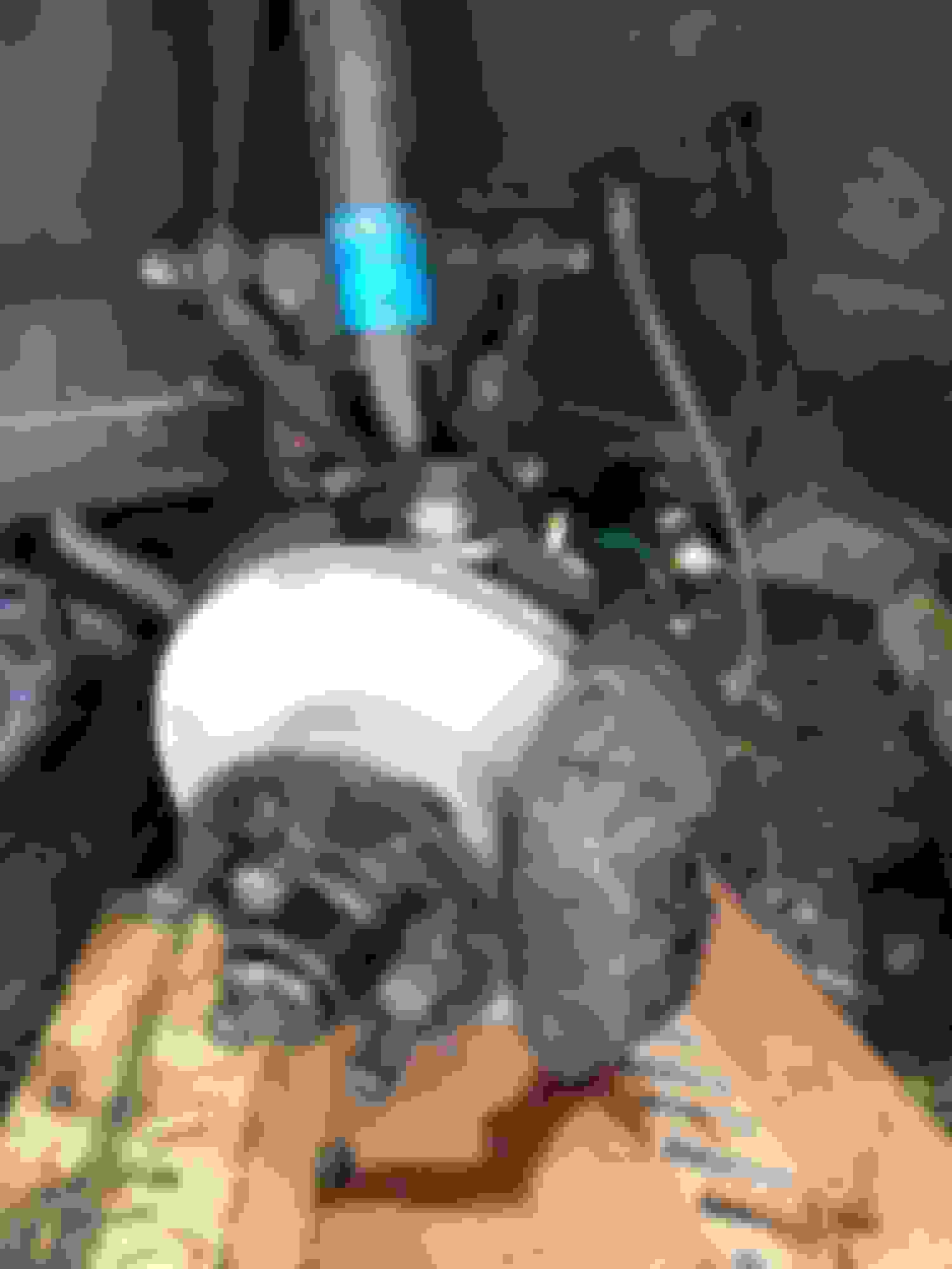
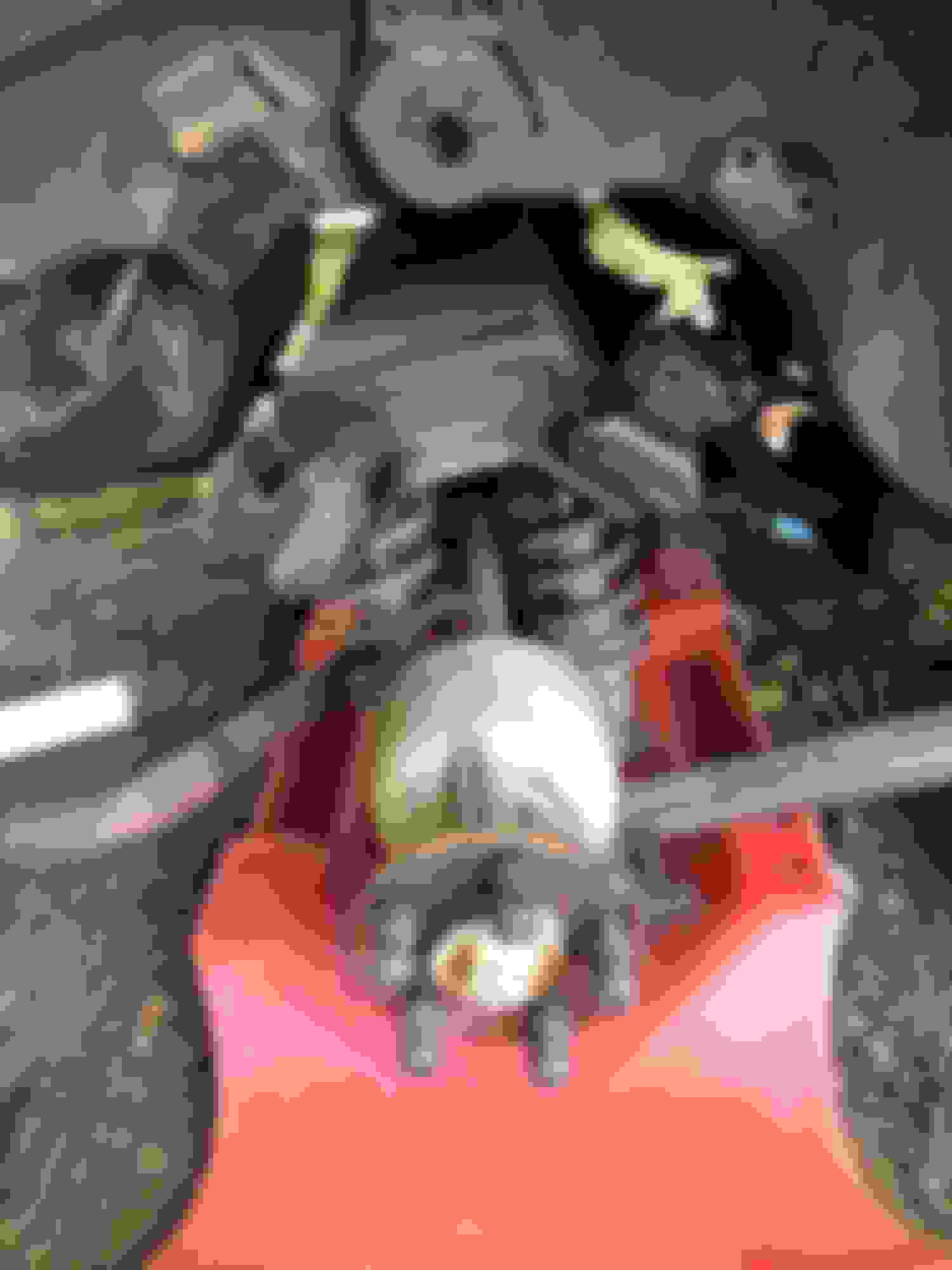
While waiting for front end parts I decided to tackle the rear brakes. Do date the rear axle is down, but still under the car. Once I’ve figured out how to undo the handbrake cable I’ll pull it out the side. It actually came out pretty easily. I was expecting the radius arms to put up a fight, everyone says they do, but they didn’t. One popped right off, the other started to tear and then popped off. The hardest thing was removing the flexible brake hose. I got the hard line detached, and could get a wrench on the locknut, but I didn’t have room to swing it. That ended things yesterday. This morning I went and bought a 15mm brake wrench. It didn’t quite fit, so I had to grind the outside a bit, but it worked eventually. Then eight bolts out, lower the jack, and I have a two wheel car! Now it’s time to go to my job. In the morning I’ll undo the handbrake and pull the rear end out the side.

 04-26-2020, 01:03 AM