When you click on links to various merchants on this site and make a purchase, this can result in this site earning a commission. Affiliate programs and affiliations include, but are not limited to, the eBay Partner Network.
Guys
A few months ago I learned that the red TPS (throttle position sensor) that fits under the capstan was NLA in its from Jaguar, and the models on sale although they look the same, are not of the same original OEM robust quality. The same going for the previous Bournes model TPS. My car has an OEM quality red TPS; but as that is now over 10 years old, a spare is an excellent idea. If the new TPS works well, I shalll carry the old TPS/capstan combination in the boot as a spare. It is a 15 minute job to swap them over. All the below operations were done on a spare capstan.
Now, being retired and liking a project, I am trying with my car to ensure I have in stock items which, if they fail, would mean the car is off the road. Most mechanical items are easily available; but electronic ones are becoming rarer; in particular the TPS is a vital part, so I started investigating Hall-effect versions, as used on all modern cars.
The TPS is actually a rheostat, that is to say a variable resistance, so as the capstan opens, the voltage sent back to the ECU varies upwards from its "throttle closed" voltage signal of 0.32v to 4.9/5v at wide open throttle. All such devices have a steady input voltage from the ECU (5v in the XJS 5.3 HE engine) and the rheostat modifies this according to the rorary position of the TPS and sends that voltage back to the ECU via a separate wire. There is also an earth wire.
In the OEM TPS, the variable resistance is achived via a "wiper" arm that touches a resistance coil, and as the wiper runs along the coil, the volts the arm sees changes with the position of the arm on the coil. The longer the effective length of the resistance the lower the voltage signal, the shorter the higher. Essentially it is a matter of how much voltage is soaked up by the resistance between the 5v input and the arm.
Again all good so far; but by its nature the arm and coil will wear as they rub against each other, consequently eventually the TPS will fail or become unreliable because it gives an inconsistent signal to the ECU. Modern cars overcome this problem by using 'Hall effect' TPSs. https://en.wikipedia.org/wiki/Hall_effect
These are named after a Mr. Edwin Hall who at Johns Hopkins University in the USA discovered that it was possible to use changes in the magnetic field of such a device to send a variable voltage signal; thereby eliminating any physical contact between the resistance and the arm. Such devices are therefore in principle more reliable and are designed for many millions of operations.
All modern cars use Hall effect TPSs and they are available in the aftermarket, particularly from motor racing component suppliers. One such being Variohm: https://www.variohm.com/products/rot...-rotary-sensor
I contacted this firm and was immensely helped by their very efficient member of staff namely: Mr. Ihsan Altintas; Office Tel: +44 (0)1327 351004: Email: Ihsan@variohm.com. They have a USA firm in the group. Between us we decided upon this one:
This item rejoices under the following reference number: 95269 1.00 EA 145.51000 /1 145.51 AM-RSS-U-111-2838- 90-37-50-R-CS (Jaguar v12 TPS) Non- contacting Rotary Sensor
This shows the sprung fork that needs to be connected to the throttle spindle. D-shaped indentation drives are also available.
Attached is a brochure about the sensors. The great advantage of them is that they are pre-programmed at the factory to the degrees of turn required from closed to wide open throttle (90 degrees in our case) and the closed and fully open voltage values (0.32 closed to 5v fully open in our case) and the rotation direction (clockwise). You still have to use a multimeter to set the closed position though, as the TPS spindle turns without stops though 360 degrees.
This TPS having been identified and bought by Madame for my Christmas present, the next problem is to connect it to the capstan spindle:
Undoing these 8mm headed bolts releases the capstan spindle
Bolts undone
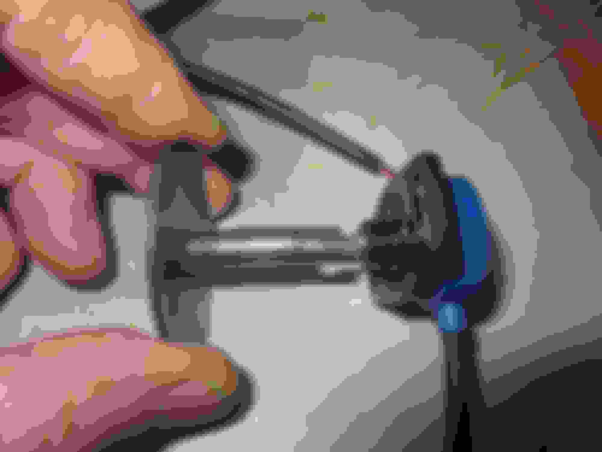
Spindle pushed out from below. NOTE from the factory the spindle is 39mm long with a D shaped end
Close up of the modified spindle. It has been shortened to 31mm and a 7mm deep 3.5mm wide slot machined into the end
Spindle reduced to 31mm long overall, a 3.5mm wide slot 7mm long has been machined in the spindle end. If a D drive TPS was selected, the shaft would have to be removed from the fixing disc and a longer D ended 8mm diameter shaft fixed to it, to engage into the TPS
Close up of the TPS sprung fork engaged in the modified spindle
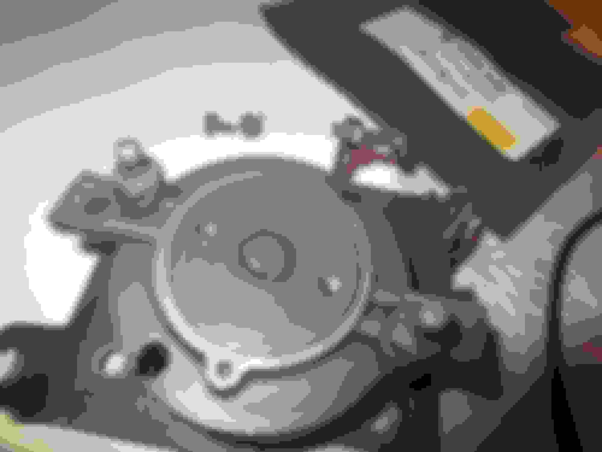
The spindle is then refited to the capstan and the TPS test fitted: Slotted and shortened spindle in the capstan, note the circular raised part of the capstan on the bottom plate
Test fitted, note the 3.5mm space between the TPS and the bottom plate, this is caused by a circular raised part of the capstan body.
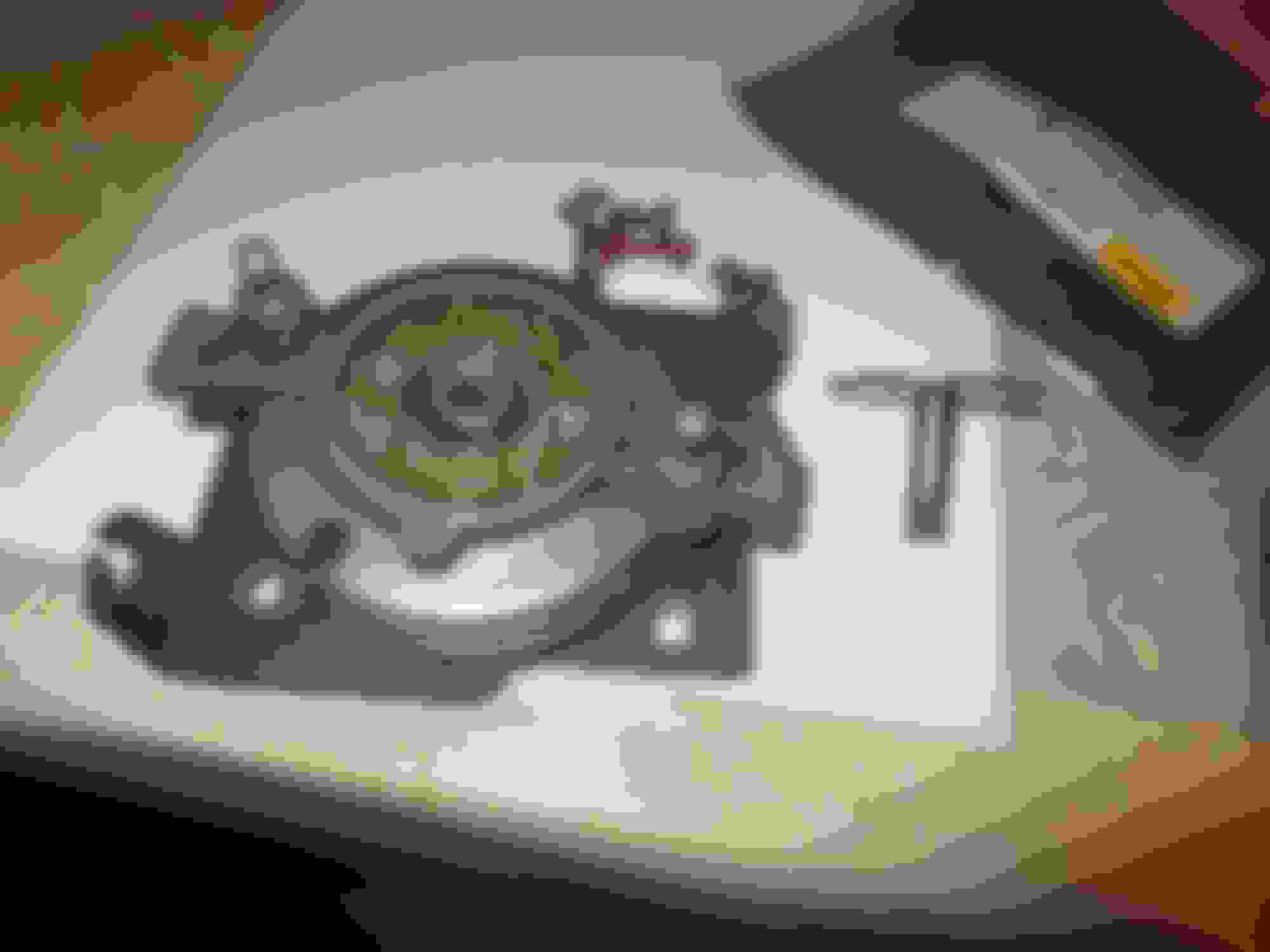
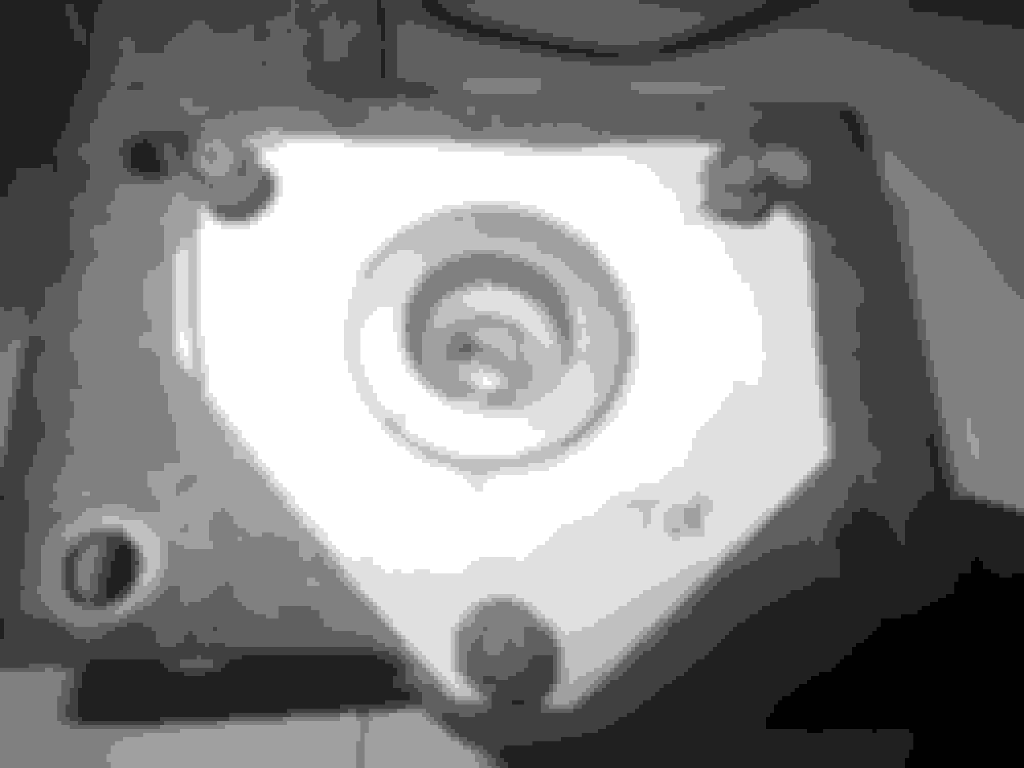
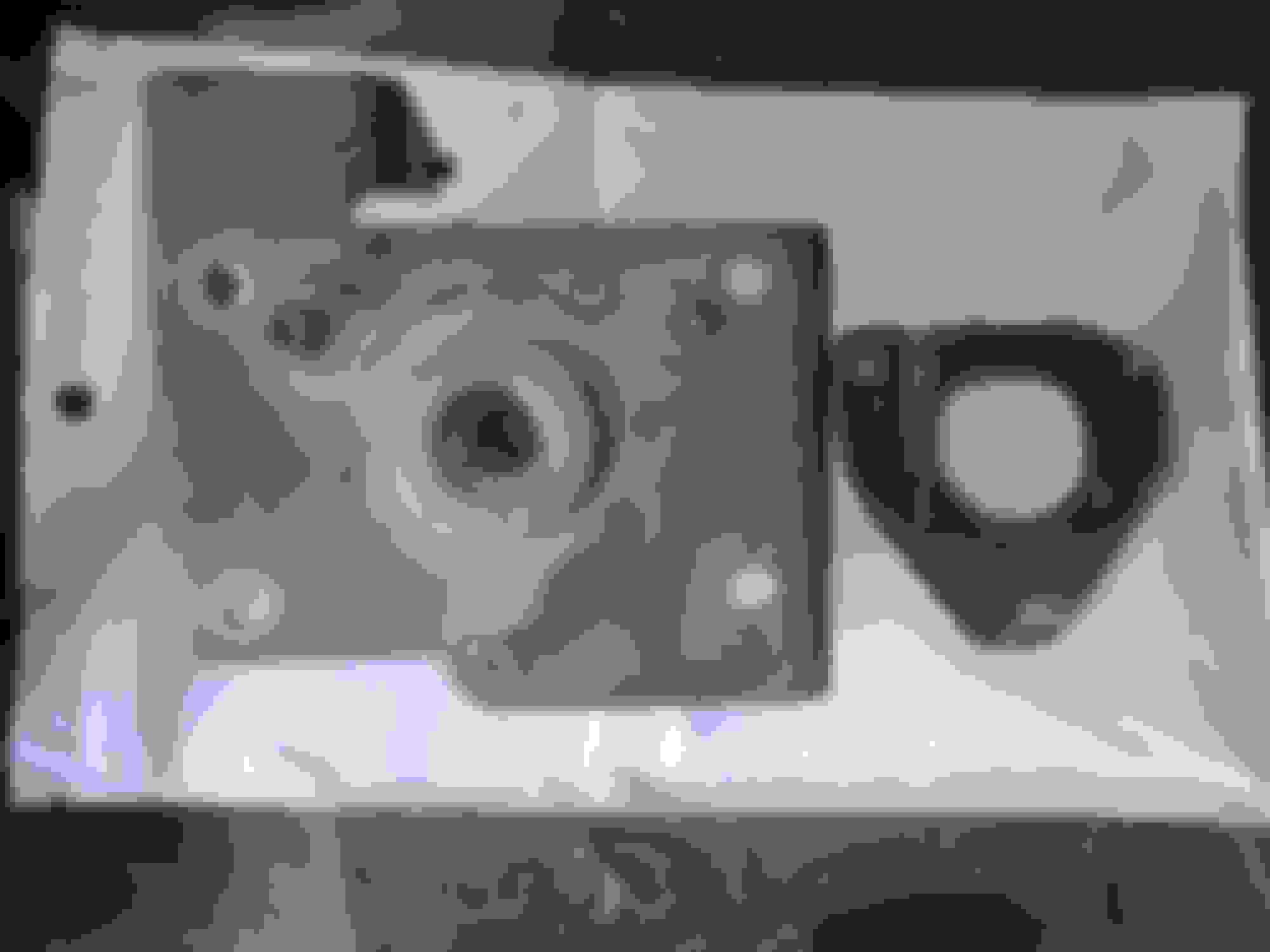
ALL 5.3 litre capstans have these screw holes, originally they directly fixed the Bournes TPS; when the later red TPS was used, Jaguar supplied a fitting kit that still used these threaded holes. This shows the template I have made to use to cut a 3mm steel spacer plate to fill up the space between the TPS and the bottom plate. The diameter of the middle hole is 30mm
When the plate is made and fitted, the TPS will be positioned using a multimeter, then two holes drilled in the base plate for the fixing screws for it. These will them be tapped for two 3mm fixing bolts
I have now got to buy 3mm steel plate to make the spacer and then the thing can be wired up. I found a suitable moulded plug so the original loom connector can be used.
More to ccome after it has been fitted and tested.
Last edited by Greg in France; 03-11-2023 at 03:33 AM.
TPS wire pigtail colours and their match to the OEM loom colours. We lack a definitive guide to the TPS wire colours (which from the TPS to the loom plug are NOT the same as the loom colours) and how they should be matched to the factory loom colours. Please refer to post 10 below for Bournes, OEM Red and the Variohm TPSs connection information.
Last edited by GGG; 03-21-2023 at 11:40 AM.
Reason: Text change at OP's request
So D shape is an option as well. Was there any reason not to go to d shape vs slot?
Hopefully this is the future. That mustang one I got works but not perfect.
Using a "D" drive version of the variohm TPS requires the OEM spindle to be removed and replaced by a longer one, as the OEM one is not long enough. The diameter of the spindle is 8mm. It can be removed from the disc part by grinding off the weld (see photo) and if needed, after that drilling it out. Then a longer shaft can be cut to length, trial fitted and the end "D-ed", and then welded to the disc. The spindle should be in place in the capstan, the disc fitted to the capstan, and then and the disc welded, to ensure it is true.
I though this might be more trouble than shortening the spindle, but experience has shown me that without access to machine tools, fitting a longer spindle is the by far easiest option. A nice stainless 8mm round bar would do it, and it is easily available.
Photo showing weld to be ground out to release the spindle: The weld between the two fixing bolts has to be ground out to release the spindle
I can tell you it is more trouble as I've tried lol. Slot it is yhen
I made a template of the required size of the plate to give me a flat surface under the capstan. Note that the large central hole is exactly 30mm in diameter:
The paper template shown in Post 1 above reproduced in 2.5mm steel plate
Template in steel alongside the capstan, the modified end of the spindle can be seen
Template in steel fitted to the capstan using the OEM TPS mounting holes
Note that altough the capstan bottom part is 3.5mm proud of the OEM plate, this plate is not 100% flat. So I used 2.5mm steel for the new plate and after test fitting added a touch of 'The Right Stuff' to the bottom of the capstan and then placed the extra plate on it, so any small gaps were filled up.
Plate fitted and a nice flat surface for the new TPS
Another shot of the plate in position
Note that on the top two holes in the photo there is not much clearance between the OEM holes and the edge of the plate. This is because the long tubular mounting spacers for the capstan have to be clear of the new plate to fit the capstan properly.
New TPS trial fitted, all perfect!
Close up of new TPS in place
Note that the final stage of the installation is as follows:
Using the loom and TPS colours connected up as per the colour chart in Post 5 above, the TPS must be positioned so that it reads 0.32v at closed throttle. Remember that the capstan is sprung to the throttles closed position. Thus I shall engage the TPS into the spindle, then turn it until I get the 0.32v reading. This must be done using a meter; but my understanding is that it will read zero until the correct point when it will immediately read 0.32v. The TPS is pre-programmed to read 0.32v at 0 degrees, changing upwards to 4.9/5v at 90 degrees of clockwise turn - corresponding to throttle closed and throttle fully open.
With the TPS at the 0.32v position, I shall mark the centre point of the TPS' two fixing slots.
These will then be drilled and tapped to accept a 4mm bolt.
Refit to car and check with meter
Tighten TPS fixing bolts.
The above photo shows the wing slots that must have fixing bolts to hold the TPS in the throttle "closed at 0.32v" position. The plate will be marked up in the centre of the slots and then drilled and tapped for 4mm fixing bolts. Note also that the new plate must be sufficiently wide so be able to accept the TPS fixings bolts in any position.
Note: I want to publicly thank my friend Jean-Jaques Loriau, chief of precision engineering company LORTEC of Toulon sur Arroux, France, for his patient help in making the spindle modifications and plate required to mount the new TPS properly.
Last edited by Greg in France; 03-20-2023 at 11:17 AM.
TPS pigtail to the OEM loom plug: how to match up the two.
The attached pdf shows the wire colours and the connections that need to be made to fit each of the Bournes, the Red OEM and the Variohm TPSs to the factory loom colours.
I ran into the same issue putting the ford mustang one on and used nuts grounded down as spacers but I do have some 1/4 aluminum stock left laying around so ill put it on the list.
Many years ago I bought a hall effect TPS for the 79 coupe.
It was from RS. It did not take much work to make it fit. RS-online.com
RS have offices in many countries.
They now sell Vishay TPSs for about US$75, but might not have the best model to suit in stock.
Other electronic outfits sell Vishay products.
In the datasheet should be one suitable.
Fixing the TPS in position:
I got the plate tapped and the TPS fixed to it. I found that I needed to put a very small 1mm washer under the TPS wings as when tightened without them the wings deformed slightly, so I cannot have been totally flat with the OEM protrusion. Using 3mm sheet for the plate would render the washers unnecessary
You can just see the washer under the wing slot
NOTE: The Variohm TPS is pre-set to order at the factory. As mentioned in Post 1 above, for the V12 5.3 you need a 90� clockwise sweep starting at 0.32 v and ending at 4.9v. There is no need to set up the TPS with a meter when you fit it. On ignition on, the chip in the TPS just starts at 0.32v, regardless of where you fix the wings to the capstan; HUGE advantage. To fix the TPS in position MAKE SURE that the capstan springs closed as easily with the TPS fitted as without. I found that placing it in position with the 4mm screws just slightly loose, operating the capstan a few times, tightening the screws a 1/4 turn between each operation, and it all tightened down with no jamming or slight resistance.
The 4mm screws give a touch of play that enables the TPS to settle to its best position.
Wiring up the TPS to the loom:
I wanted to use the OEM loom female plug, into which the OEM male TPS pigtail and plug fits, as this enables swift change-over to my spare capstan/OEM TPS if needed. At this point there are two things to consider:
If you have a RED OEM TPS to sacrifice, joining the wires from its plug/pigtail is straightforward, as the wires are very fine like the Variohm ones.
I had a Bournes unit that I sacrificed to get the pigtail/plug from, so I had to join the very fine Variohm TPS pigtail wires (maybe 1mm diameter) to the far thicker 4 mm OEM pigtail wires from my old Bournes unit. I did this first directly, but got duff connections that threw me into despair when the new TPS did not function properly on its first test!
The Franco/Oz hotline was red hot this morning, follow up to an email to the Wizard of Oz, and we deduced that it must be the joins, as sometimes I could hear the injectors click when I opened the throttles. So this is what I did:
I have some top notch silicone coverd wire in about 2 to 2.5 mm diameter. I cut a length of this in the required three TPS pigtail colours. These I joined to the Bournes pigtails, as they were sufficiently close in diameter to make a good twisted-together join and the the joins were made good with those heatshrink tubes with solder in them. Over this went two layers of heatshrink insulation.
Then the silicone wires were joined to the Variohm pigtails - again being closer to the same diameter, using the same system. Result, see photos here:
Bournes plug pigtails connected
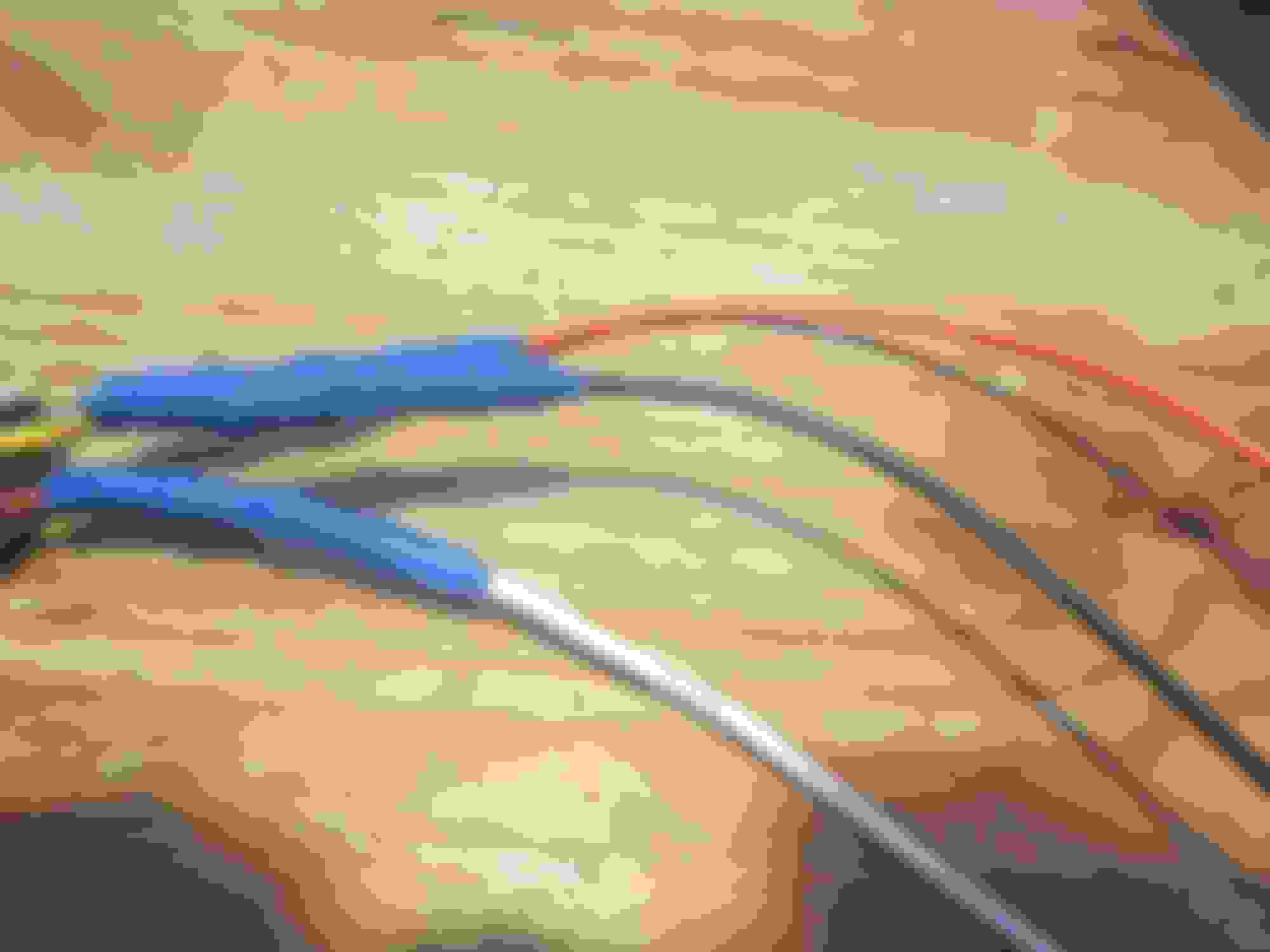
This pic shows the smaller diameter silicone wires the Bournes pigtails are connected to and the Bournes wire colours joining to the Variohm wire colours
Close up of the silicone wires loaded with the solder shrink tube and the two heat shrink outers.
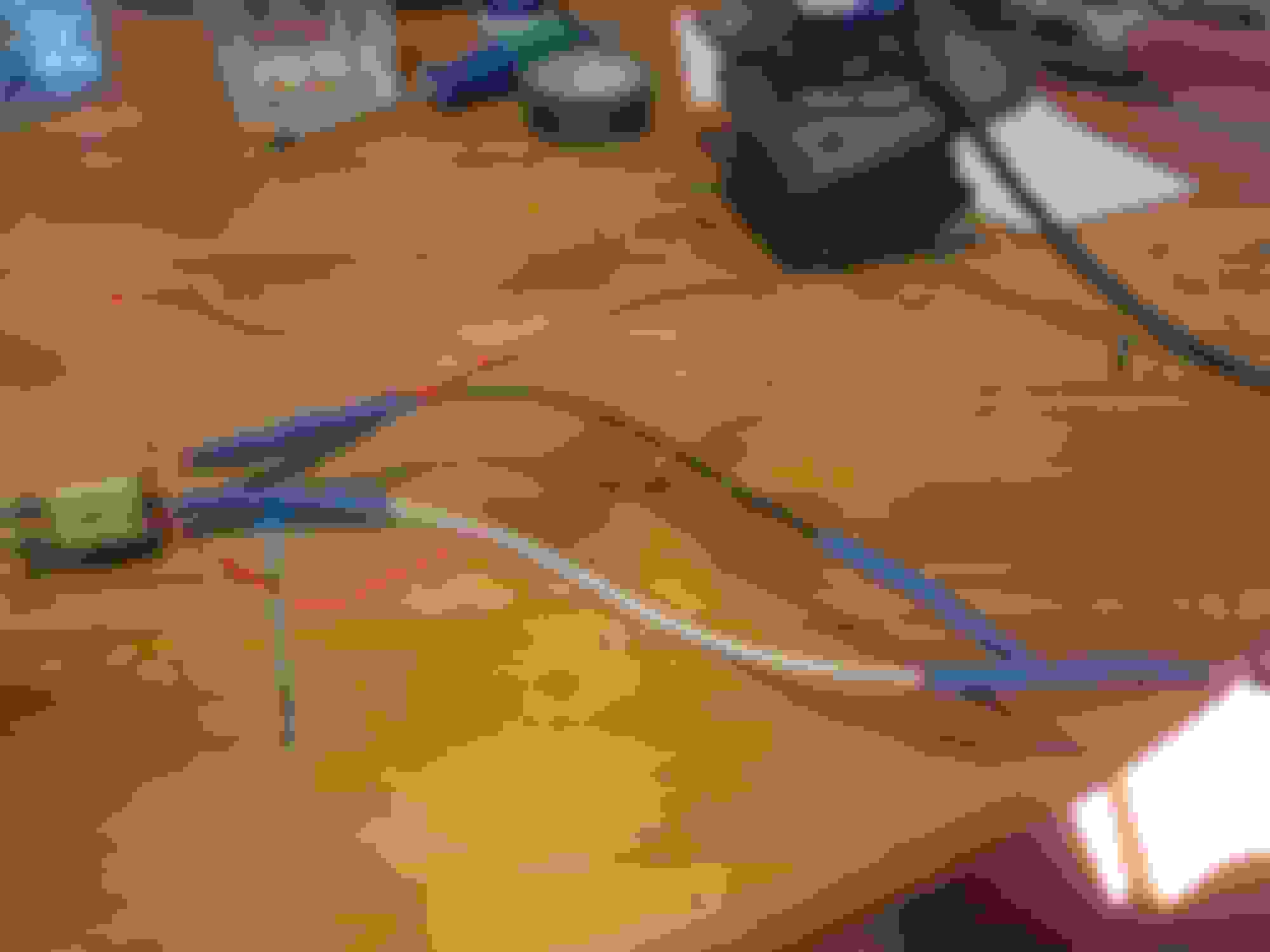
This shows the silicone and the variohm pigtails ready to be twisted together and then solidly attached using the tubes shown in the previous photo
The solder tube ready to be heat shrunk
This shot illustrates the Bournes/Variohm colours to be joined, as set out in the attachment to Post 10 above. NOTE the OEM Red TPS pigtail colours are NOT the same as the Bournes colours! Post 10 shows the correct connections to the OEM Loom plug for Variohm, OEM Bournes and OEM red TPSs.
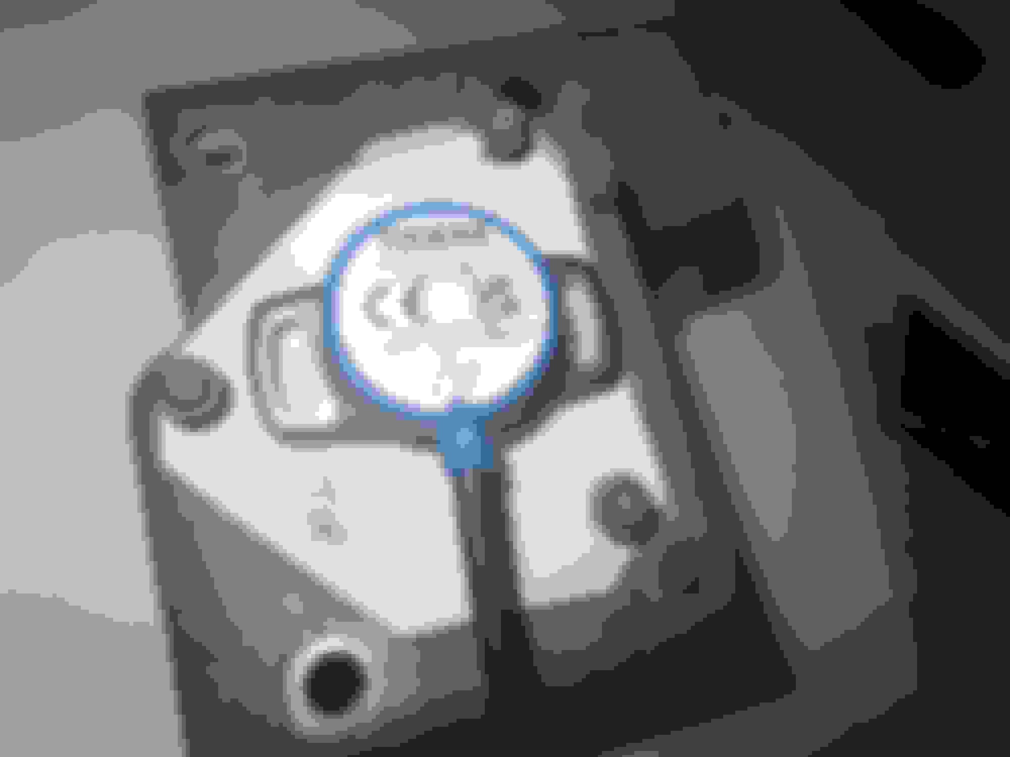
The three attached wires at the silicone/TPS joins were carefully wrapped together in self amalgamating tape: Blue box shows the self amalgamating tape wrapping the TPS/silicone joins. The red lines/circle shows the GiF patented two-capstan method of testing the system! The new Variohm TPS is connected to the loom, the throttle capstan is connected to the throttles but not the loom.
This time with better connections the static test was 100% successful! Ignition on, I started the car and then turned the two capstans in sync, and the car revved and ticked over absolutely perfectly. A HUGE relief after my previous attempt when the thing would not rev and generally acted up!
Tomorrow the road test, so fingers crossed...
Last edited by Greg in France; 03-22-2023 at 01:37 PM.
Further note on the OEM red TPS' performance:
When I unplugged the capstan with the OEM red TPS, I had my meter handy, so I thought I would test its voltage at the closed position.
This was a new OEM red TPS bought and fitted in 2011, since when the car has done maybe 30,000 miles. I had set it to dead-on 0.32v in 2011. The TPS had not physically moved at all.
It tested at 0.21v throttle closed! I was astonished. I unscrewed the wing fixings and had to loosen it from its position with some grips, so I was sure it had not moved. I reset it to 0.32 volts and tightened it down. Perhaps more worrying/interesting, the OEM TPS having been reset, topped out at 4.6v at WOT. This being below spec, though as the engine wil be at full rich at that point, I expect it does not matter.
I spoke to Grant about this, and he said that years ago resetting the TPS voltage was on the main dealers' major service list (probably at 25,000 miles or so). Now as this change cannot be because the TPS body moved, it must be caused by internal wear, which is where the Hall effect TPS will in theory anyway, be at a great advantage with no internal touching wear parts.
Anyway guys, I strongly recommend checking the OEM TPS closed throttle voltage every two or three years and adjusting as needed.
Finally, the Varioihm TPS will not need checking as it is programmed to the required voltage sweep; of course, like all electronic things, there is always the risk that the day may come when it just stops working! Hence the old capstan/TPS will be in the boot.
Last edited by Greg in France; 03-23-2023 at 12:25 AM.
Road test report:
Fitted the capstan with the new Variohm TPS today. Car started right up, ran perfectly from stone cold. On the road, quieter, smoother, felt faster too. At high revs far smoother, certainly les accelerator depression for a given speed.
I think that the ECU is getting more accurate signals, or a more accurate actual butterfly position as a result of a more accurate TPSvoltage signal, and this giving better fuelling.
Whatever the reason, this has made a very noticeable improvement and I am extrememy pleased. Definitely recommended! The fuel computer shows, if anything, slightly better MPG, but this is only over a 25 km test at all sorts of speeds.
I think anyone wanting to get the best out of the engine would find this a worthwhile upgrade. And apart from the work to install it mechanically, the cost of the TPS is les than available Lucas replacements, though there are cheaper ones advertised of unknown reliability.
Last edited by Greg in France; 03-23-2023 at 01:16 PM.

 03-10-2023 | 08:49 AM