When you click on links to various merchants on this site and make a purchase, this can result in this site earning a commission. Affiliate programs and affiliations include, but are not limited to, the eBay Partner Network.
I have been asked a couple of time about the LED conversion I did for my failed optic fibre lights. Here is a brief write up of how I replaced the optic fibre with LED's
I hope it helps, and if anyone has any questions don't hesitate to ask.
Won't let me upload the doc as it ios too big with the pics so here it is in full hand. Take 2
My optic fiber was about done for, a few of the fibres were broken so it was time to replace everything with LED's.
Self adhesive trip LED's were added to the panel behind the AC controls. These were wired into the dash light circuit so they work with the dash lights with dimmer function. Just be aware that LED's are polarity sensitive so if you wire then backward they will not work. These work directly off 12V so no need to add resistors.
I then drilled holes in the back of the fascia so the LED light illuminates the controls. I removed the black plastic by prising off the retaining clip on the metal centre.
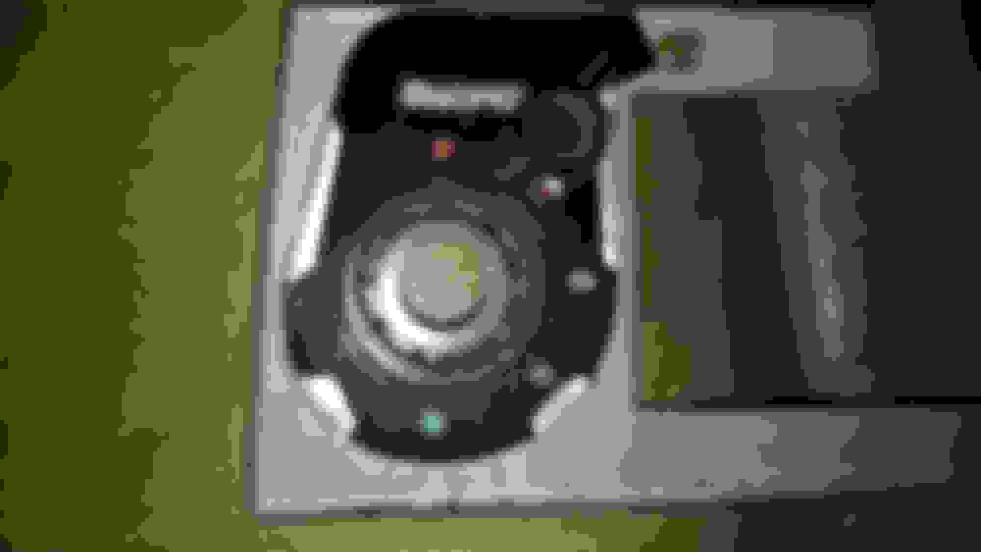
This is the rear of the ignition switch surround. Remove the fibre optic cable and a LED fits nicely in its place. Inside the heatshrink is a resistor to limit the current, if you do not add a resistor the LED WILL FAIL. Anything between 2 and 3K ohms will work 2.2K and 2.7K are standard values. The long leg of the LED is +. Then wire these into the instrument cluster light circuit.
 09-12-2019, 03:14 AM