I'm back to work on the Short in my ABS !!
#21
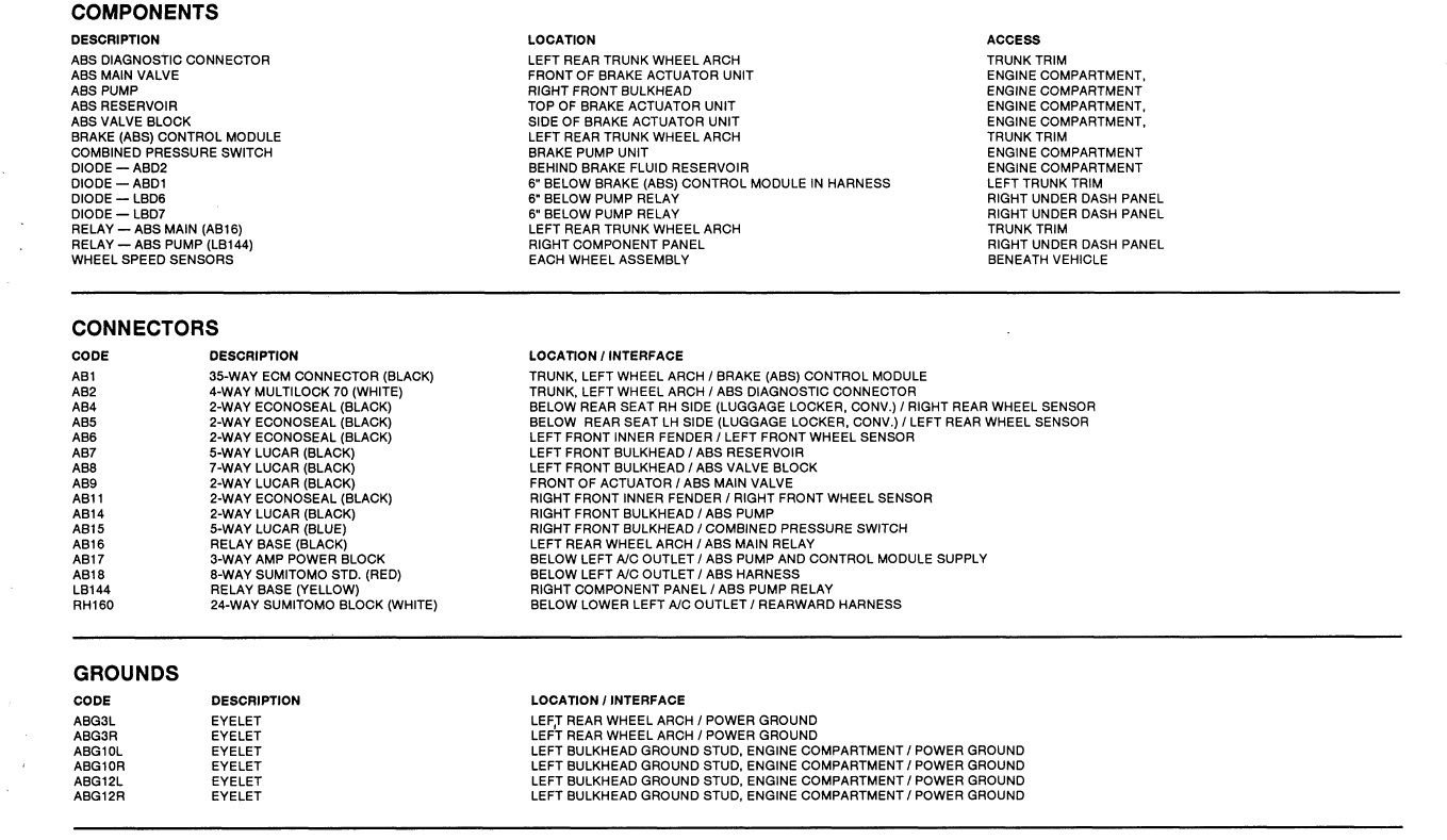
I meant, my Guru !!! Where is the diode located ?? Wiring shows 2 ABS relays. I could only find the one mounted on the left frontmost post near the water overflow and fill. That should be the main relay ?? So where is the pump relay ?? or vice versa ?? Looks like the other connects to the ignition somewhere. All else is functioning so I would "assume" the ECU is working OK. Seems like it has to be a pinched wire... ??
#22
#23
#24
In the abs wiring diagram (fig 27.1) the 30 amp fuse that is blowing is located in the center top and it's the one with the brown and orange wire which then goes to the relay DAC 4506, through the open/close then to the pump via the brown and orange wire. There is no continuity between the two as I would expect since the ignition switch is not on and the fuse does not blow until 10 seconds after the ignition is on. I think that would rule out the brown wire to the battery ?? but not the brown orange wire to the pump which also shows no continuity ??
#25
I don't understand what you mean by the NO wire has no continuity, where are you measuring NO to ground or end to end of the wire?
The NO wire is only a couple of inches long as the ABS relay is next to the 30A fuse. The NU (Brown/Blue) goes from the ABS relay to the pump. You said the pump runs for a few seconds is this correct?
The NO wire is only a couple of inches long as the ABS relay is next to the 30A fuse. The NU (Brown/Blue) goes from the ABS relay to the pump. You said the pump runs for a few seconds is this correct?
#26
What would the danger be of hooking up the brown wire that goes to the fuse that is blowing and hooking it up to the brown orange wire coming from pin 87 on the pump relay under the dash ?? Must be some way that I can narrow down where the heck the short is?? On the figure 27.1 it shows the brown orange wire going through a CP7 which is something ?? then one wire goes to the pump and the other to the main valve.... Could it be the brown wire coming from the battery spur that is pinched ?? Where do they connect to the battery ??? I could check continuity to the switch ??
#28
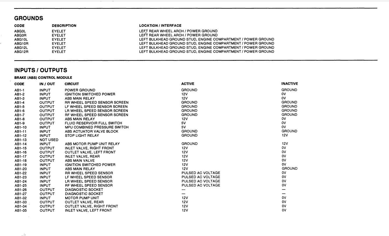
I cut the brown/blue wire from the pump and when I connect a meter to the loom side, it grounds out and I don't believe it should ?? The wire where I cut it is fine to where the brown/blue wire goes into the wheel well area on the driver's side and has continuity. The wire going into the wheel well grounds out ?? Where does this wire go as I don't believe it should ground out ?? Does it run under the center console to the ECU pin 32 ?? If so, should I check the continuity from there to where I cut it where it enters the wheel well on the driver’s side. ??
By the ecu, I found a seimens relay V23134_A55-X80. It has 85,86 power two 87s and a 30 between. I also have a spare that is the same but the two do not test out the same ??? How do I find out which one is correct ??
By the ecu, I found a seimens relay V23134_A55-X80. It has 85,86 power two 87s and a 30 between. I also have a spare that is the same but the two do not test out the same ??? How do I find out which one is correct ??
#30
#31
OK.. after tracing the wire to the console, I found where the brown/blue connects to a black via a diode. The diode does not have continuity in one direction but has a little bit in the reverse direction. my meter shows it to be: 5 17 with no . anywhere ?? So I would assume the diode is bad... Ebay and Amazon have them. It is a 3Amp 600V 1N5406. with the positive lead from my meter on the brown/blue side and black on black, there is no continuity but reversing the leads result in the other reading... Do I assume that there is some flow and in which direction... And would this be correct ?? While the diode is disconnected, I forgot how to check the wires to see if they are grounding out anywhere back to the pump...
#32
This is correct.
#33
I cut the brown/blue wire from the pump and when I connect a meter to the loom side, it grounds out and I don't believe it should ?? The wire where I cut it is fine to where the brown/blue wire goes into the wheel well area on the driver's side and has continuity.
with the positive lead from my meter on the brown/blue side and black on black, there is no continuity but reversing the leads result in the other reading...
??
with the positive lead from my meter on the brown/blue side and black on black, there is no continuity but reversing the leads result in the other reading...
??
The meter reading at CP7 reads ok is this with the NU wire cut?
#34
#35
#36
The black wire is ground and should be connected to the Brow/Blue (NU) wire via the diode, from what you said in your last post that diode is good and does not need to be replaced.
You did not answer my last questions.
Where did you cut the NU wire?
Which side of the loom had a short (continuity) to ground. The pump side or the car side?
You will not find this problem by just replacing bits, you need to work through each circuit in a methodical process.
You did not answer my last questions.
Where did you cut the NU wire?
Which side of the loom had a short (continuity) to ground. The pump side or the car side?
You will not find this problem by just replacing bits, you need to work through each circuit in a methodical process.
Last edited by warrjon; 04-24-2017 at 04:03 AM.
#37
Join Date: Nov 2013
Location: Inverell, NSW, Australia
Posts: 3,052
Received 1,442 Likes
on
898 Posts
A faultfinding tip - use an incandescent light bulb 20watts will do (in this situation) and solder a couple of wires to it with spade connectors on the other end. Remove the (circuit) fuse and insert the light.
The light will glow when there is a fault drawing excess current. Will prevent damage to upstream components and saves replacing fuses all the time.
The light will glow when there is a fault drawing excess current. Will prevent damage to upstream components and saves replacing fuses all the time.
Amidst the frustrations of tracking down the OP's issue, I could not let this pass without suggesting you be awarded this month's Golden Spanner Award for the Top Tech Tip. Comes with a lifetime personal supply of gremlins . . . LOL.
Cheers,
Ken
#38
Warren,
I understand but thought the diode might be bad no biggie to replace. After I unwrapped the brown/blue wire from the pump to the grommet, I cut the wire before the wire went through the grommet and it checked out fine to the pump. Then I checked the wire to the diode and it checked out ok.. no resistance anywhere. So I put them all back together and now have a wire with no resistance from the diode to the pump. Put almost everything back together except for a 3Amp fuse on the passenger side I found on the floor and started, drove forward and down the block and the anti lock light is on and there is no brake assist. No blown 30 amp fuses !! So need to go look and see where this 3 amp fuse is on the electric diagram ?? Ken
I understand but thought the diode might be bad no biggie to replace. After I unwrapped the brown/blue wire from the pump to the grommet, I cut the wire before the wire went through the grommet and it checked out fine to the pump. Then I checked the wire to the diode and it checked out ok.. no resistance anywhere. So I put them all back together and now have a wire with no resistance from the diode to the pump. Put almost everything back together except for a 3Amp fuse on the passenger side I found on the floor and started, drove forward and down the block and the anti lock light is on and there is no brake assist. No blown 30 amp fuses !! So need to go look and see where this 3 amp fuse is on the electric diagram ?? Ken
#39
Hey Warren . . . this is a GREAT piece of advice and should appear in all our workshops. For the sake of completeness, we should underline that is a 12Volt 20Watt incandescent - a 21W stop light bulb is ideal - limiting circuit current to a max of around 2A. I have several of these (and 12V 60W headlight bulbs for 5A) soldered to either 3AG or Spade fuses.
Cheers,

Ken
Cheers,
Ken
I used to work as a bench tech for Marantz, learned this trick from one of the other techs, been using ever since 35years now.
#40
I would be looking at the loom where it goes through the grommet, if it's going to short anywhere that's where it will be.


