
pickup coil

#82
 06-09-2012, 04:47 AM


OK.
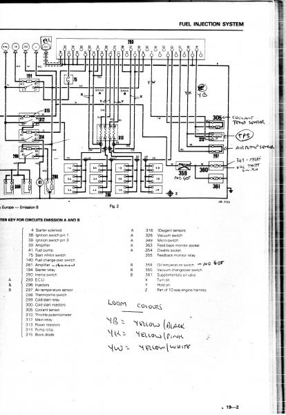
My wiring "pin outs" from the factory books I have on hand, and what I have used on many over the years, is
ECU pin:
7 = TPS wiper.
19 = TPS centre, and also ONE terminal of the CTS.
20 = TPS end, and also one terminal of the ATS.
5 = 2nd terminal of the CTS.
21 = 2nd terminal of the ATS.
It is that simple, and if wires are crossed havoc follows??.
#83
06-09-2012, 06:12 AM
#84
06-09-2012, 06:50 AM

#86
06-09-2012, 07:55 AM

M90, this all started a long time ago when you replaced the Bournes pot with the Mustang pot. We've pretty definitively ruled out the CTS so it's got to be the pot. I have a spare Bournes pot I can send you for troubleshooting if you want -although it seems like more of a wiring issue than the pot itself. PM me if you're interested.
#88
06-09-2012, 05:47 PM
Pm replied, but I advise before I send you the pot to triple check the wiring, and also when you reinstall my pot to check it again to make sure everything is going to the correct pin. I almost wonder if you're simulating a WOT condition by either sending afull 5v to the ECU or no signal at all (not sure which would simulate full throttle).
#90
06-10-2012, 02:18 AM

Veteran Member
Try putting in a spade connector back near the ECU plug in for the two CTS leads and run a new connector and new temporary wires. Just run them up over the top of the car, and just for the CTS, to bypass the entire wiring harness. This will rule out the loom entirely. There's way more to the wiring loom than just the underhood stuff you've replaced.
When I did control work for commercial HVAC installs, I had a school where I couldn't pick up about half the thermostats on the network. After searching for weeks I found where a careless dropped-ceiling installer had put an anchor right through my network wire.
D
When I did control work for commercial HVAC installs, I had a school where I couldn't pick up about half the thermostats on the network. After searching for weeks I found where a careless dropped-ceiling installer had put an anchor right through my network wire.
D
Greg
#92
06-10-2012, 09:56 AM
#93
06-10-2012, 09:59 AM
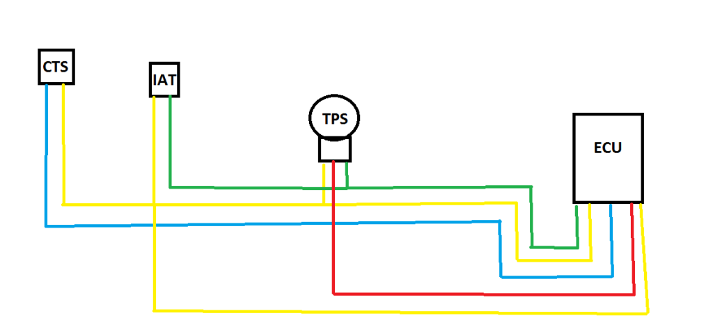
If anybody could verify this for me, it would be a big help. i vaguely recall seeing the CTS wired through the high side (green) and the IAT wired through the low (yellow), but perhaps its just my imagination.
this diagram shows exactly how its currently wired.
this diagram shows exactly how its currently wired.
#94
06-10-2012, 12:07 PM
Veteran Member
TPot wiper output goes to pin 7
Tpot 5v input comes from pin 20 which also feeds ATS with 5v
Tpot output non-wiper (ie after the 5v has gone through the resistance, but not including the wiper output) goes to pin 19
CTS output (ie after the 5v has gone through the resistance of the sensor) also goes to pin 19
CTS 5v input comes from pin 5
ATS output (ie after the 5v input has gone through the sensor) goes to pin 21
Pin numbering starts from RHS BOTTOM as you look at the pins (ie the other way from normal reading of words on a page). Pin 5 is therefore the fifth pin along from the bottom row RHS. Pin 7 is the seventh pin along from the RHS bottom row. Pin 19 is the first pin on the RHS top row. Pin 20 the second along from the RHS top row. Pin 21 is the third from the right on the top row. All as you look at the ECU pins head on.
Greg
Last edited by Greg in France; 06-10-2012 at 12:10 PM.
#95
06-10-2012, 03:14 PM
whups, sorry. on my diagram green is low resistance, yellow is high resistance and red is wiper. colors matching the TPS harness. i think the high resistance side (yellow) should be going to the IAT and low resistance (green) should be going to the CTS but im not sure and the schematic doesnt specify which side is high or low.
Last edited by M90power; 06-10-2012 at 03:30 PM.
#96
06-11-2012, 10:48 AM
Senior Member
#97
06-11-2012, 12:44 PM
as far as i can tell theyre correct, and i did a bunch of research trying to find the correct sequence. yellow to high, green to low, and red to wiper.
i will say this. the other day i had a little bit of slop in the throttle linkages, from when i changed the plugs, and when i touched the gas the TPS turned but the throttle plates hadnt yet absorbed the slack and the motor started to bog out from over enriching. once i took every last bit of slack out of the linkages, the phenomenon was gone.
i will say this. the other day i had a little bit of slop in the throttle linkages, from when i changed the plugs, and when i touched the gas the TPS turned but the throttle plates hadnt yet absorbed the slack and the motor started to bog out from over enriching. once i took every last bit of slack out of the linkages, the phenomenon was gone.
Last edited by M90power; 06-11-2012 at 12:46 PM.
#99
06-11-2012, 03:09 PM
#100
06-11-2012, 09:23 PM
They will do a huge difference if your pre-cats are partially clogged. Keep in mind, that motor will not run 100% right, with both sensors out, however you will feel immediate throttle response difference.