When you click on links to various merchants on this site and make a purchase, this can result in this site earning a commission. Affiliate programs and affiliations include, but are not limited to, the eBay Partner Network.
Guys
Sad to report, even after my gearbox replacement, refixing of the rear axle inner dog bone fulcrums, and total renewal of the front suspension, my lowish frequency vibration up through the floor is not totally cured. I appears at about 115 KPH (70 MPH) and is worse or better depending upon load, deceleration, acceleration etc etc.
So with some trepidation I have embarked, after much discussion on the France/Oz hotline, on renewing the UJs in the rear driveshafts. I am doing one side at a time to ensure as far as possible I do not get lost in a sea of bits.
Following in the footsteps of Darren largely, this is what I have done so far:
Remove the split pin and undo the castellated nut on the outer end of the driveshaft. This requires is a 1&1/8th A/F socket and the driveshaft has UNF threads. I used a mains impact driver on it and it came off in no time.
To get to the outer UJ it is necessary to remove the hub from the driveshaft splines. I tried a hub puller and no dice. So nothing for it but to remove the hub and driveshaft as a unit.
To do so I undid the inner flange that connects to the diff (4 11/16s A/F sized bolts) again with the impact driver and an extension. Again off they came no bother.
Filthy does not begin to describe the hub and UJ, caked on grease and grit etc etc, so into the bath of parrafin they went for 48 hours. After that a good brushing and a blast with a brake cleaner aerosol made they semi-respectable.
As Darren warned me, it is necessary to remove one of the two shockers to get the driveshaft/diff flange out.
Then it is necessary to remove the hub bottom fulcrum pin and the assembly comes free.
By now I have a hub with the driveshaft dangling from it, and its off to the tractor and Heavy machinery place to beg a go on their 40 tonnne hydraulic press. The son of a friend works there and he got stuck in. At 30 tonnes there was a bit of a crack and the splines moved about 10mm! And this was a press that delivered shock loads, not just continuous pressure. Further 30 tonne efforts and eventually, 10mm at a time, with a great crack each time, it eventually came out. this process totally ruined the bearings however, as they take all the load.
The actual hub easily taps free of the aluminium hub carrier casting, tapping outwards. There are two bearings in the hub assembly, an inner one which stayed in the hub, and an outer one the race of which is a press fit onto the hub and the outer cone of which stayed in the aluminium hub casting. Both bearings have grease seals which are pressed into the hub carrier on the outer ends.
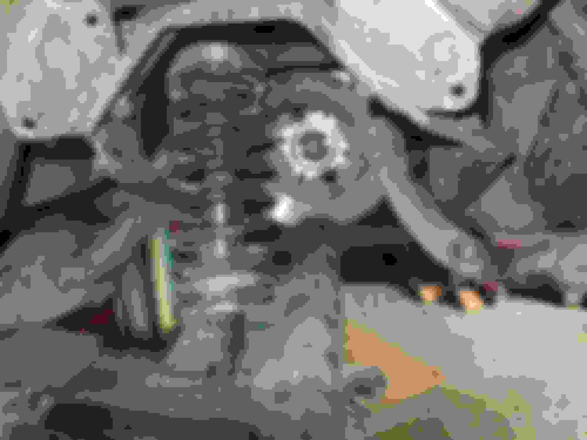
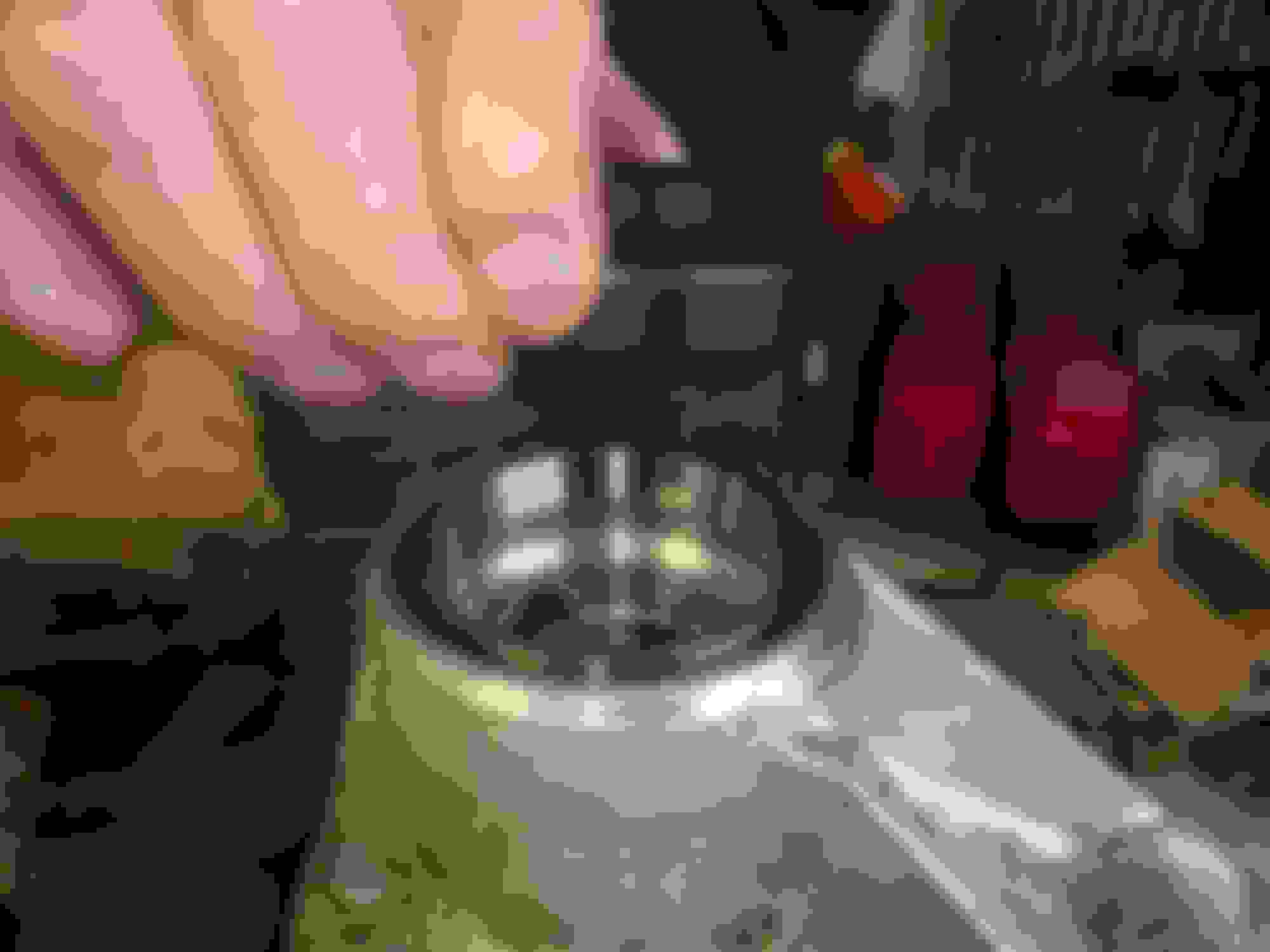
As an useful aid to anyone wanting to grasp the parts layout, here is a sequence of photos starting with an exploded view:
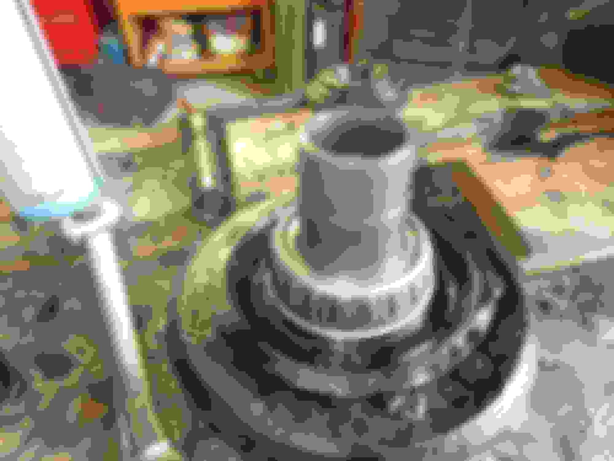
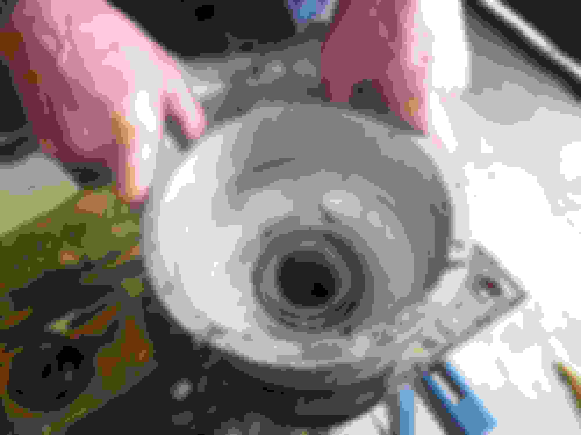
Next comes a close up on the hub itself showing the race of the outer bearing still on it:
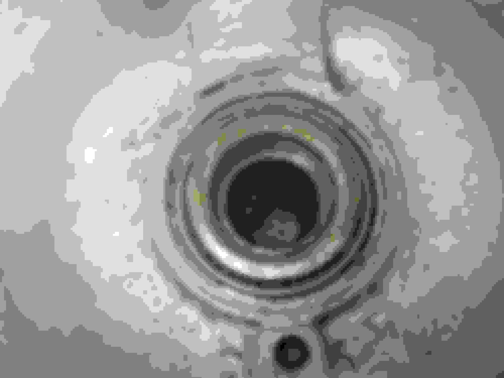
Now a shot of the hub carrier aluminium casting outer side showing the grease seal and the bearing outer still in it. The impact striations caused by the hydraulic press can clearly be seen on the bearing outer, as well as the outer being actually cracked!:
Next comes a pic of the inner side of the hub carrier, showing the inner bearing - which is the smaller of the two - still in place under the grease seal, which has a metal outer with "retainer" stamped into it:
The next pic shows a close up of the spline end of the driveshaft with the important phosphor bronze endfloat spacer, as well as the large standard silver-coloured spacer behind it. As the splined driveshaft fits into the hub, the outer castellated nut, when torqued up, has basically the same effect on the assembly as the nut on the front wheel stub axle has on the bearing and hub assembly at the front. It must be tight enough to hold the bearings properly in place but not too tight to ruin them, or too loose which would have the same effect. The difference is that rear hub has to have the driveshaft very securely and tightly bolted into the assembly. The phosphor bronze spacer allows the castellated nut to be torqued up onto the driveshaft to 140 ft/llbs without over-tightening the bearings as it acts to limit the degree to which the bearings can be tightened.
I am told that, even with new bearings fitted, provided no other components have been changed, the same phosphor bronze spacer will be correct, as the beatings are made to such fine tolerances. The correct endfloat for the rear hub bearings is between 2 thou float and 2 thou preload, with the ideal being zero. I understand, and am open to correction, it must be set by assembly without the spacer, measurement , of the float and then the purchase and fitment of the required spacer to give the correct final result.
As can be seen, the splines and the hub are very rusty, so they will be given the phosphoric acid treatment once the UJ has been removed from the splined part of the driveshaft tomorrow. Also, as in this last photo, the threads of the driveshaft will have to be fixed, again because of the huge force needed to remove the splines from the hub!
More posts will follow as I (hopefully) progress!
Last edited by Greg in France; 11-19-2019 at 04:17 AM.
The rear axle is now in the car with new UJs and new hub bearings. I am writing a PDF of how it was done, with photos, as I hope that might be useful to have on the forum. Most particularly, I could not find any clear info about the spacers and how to measure them, and I will ensure this is clear. Meanwhile, here are a few notes and pics:
I made up this little effort to help the UJ tool sit more easily on the outer edge of the driveshaft yoke when pushing in the new UJ caps. Without it it tends to slip off. Of course you need the hole it fills when removing the old caps:
This is the hub carrier, old bearings driven out, cleaned up and ready for the new ones, and then showing the new outer bearing outer race being driven into place:
The OUTER race of the inner bearing has to be wound into place with a threaded rod, as it is shrouded by the hub carrier:
Then the inner race of the OUTER bearing has to be driven onto the hub tube:
Then insert the outer grease seal into the hub carrier, this photo also shows the two outer races in place
Now the hub with the outer bearing inner race on it, is dropped into the hub carrier so it is properly in its outer race. The assembly is then turned over and the inner race of the inner bearing is placed onto the hub tube poking through the carrier:
This inner bearing inner race is a VERY tight fit on the hub tube and needs to be wound onto it to get it sitting properly against its outer race in the hub carrier, after a few taps with a bearing driver and a hammer to get it started over the hub tube:
Now comes the only really tricky part: measuring the required endfloat spacer. I took two snaps of the exact bit you have to measure. It is the space between the end of the hub tube (see pointer in this snap):
and the top of the inner bearing inner race (see pointer in this next snap). The bearing is higher than the end of the hub tube and the spacer goes in to equalise the two, so they are level, plus a couple of thou. Though actually a slight preload of 2 thou, or endfloat of 3 or 4, will be quite OK:
Then, using an electronic calliper thingy, measure the distance between the two. BUT BEWARE, the inner race if the bearing will need to be tapped down with a drift to ensure the measurement is the same all round the circumference of the inner race:
And here is the spacer that goes into the gap. It is actually placed on the splined part of the driveshaft when the driveshafts are being assembled into the hub. These spacers are available from SNG Barratt in all the required steps of sizes. The spacer sits on top of the hub tube and just fills the space between the top of the hub tube and the top of the bearing inner race, thus ensuring that when the driveshaft is inserted and tightened into the assembly to 140 ft llbs, the bearings are not squashed together, as the tightening load is all on the hub, from the outer end by the wheel studs to the inner end of the hub tube carrying the bearings:
Time for breakfast now, but the next installment will show how I installed the UJs into the driveshafts, and the drive shafts into the hub.
Last edited by Greg in France; 12-31-2019 at 06:25 AM.
I am told that, even with new bearings fitted, provided no other components have been changed, the same phosphor bronze spacer will be correct, as the beatings are made to such fine tolerances.
First cuppa coffee disclosure here
Bearing precision notwithstanding it would depend the the new bearings being pressed to exactly the same location on the shafts, wouldn't it?
The correct endfloat for the rear hub bearings is between 2 thou float and 2 thou preload, with the ideal being zero. I understand, and am open to correction, it must be set by assembly without the spacer, measurement , of the float and then the purchase and fitment of the required spacer to give the correct final result.
My impression is that the hubs and bearings are very forgiving as far as clearance goes, as I am certain many have replaced the bearings and never gone thru the process of checking the clearances, and reported no problems. At least, no immediate problems. Not that I'm condoning the practice, mind you. I'm sure you'll go by the book.
I remember from 20+ years ago my first Series III. The rear wheel bearings had considerable play, probably 10 thou at least. There was never any noise or vibration or ill-result that I could hear, feel, or see. I never did do anything with them. When I last heard from the new owner there were no problems even at 175k miles. I suspect the robust size of the bearings comes into play here, and doubly so since (as we know) ensuring they stay well greased is a bit of a fingers-crossed situation.
Rambling a bit I'll mention that, years ago, I replaced rear bearings on a couple older Corvettes. They have a similar rear bearing arrangement and clearance checking process. Cleverly, someone dreamed up a dummy shaft to ease the process although, at the moment, I can't quite remember how it works.
Bearing precision notwithstanding it would depend the the new bearings being pressed to exactly the same location on the shafts, wouldn't it?
Doug, presumably the outer tapered part of each bearing will be, as the hub carrier will be the same one as before?
The inner races of the large bearing will be pressed onto the same hub, too.
But having said that, your point about the assembly being forgiving is most reassuring!
SO, how do the U-joints feel?
Any binding or rough spots ?
Cheers
DD
Doug,
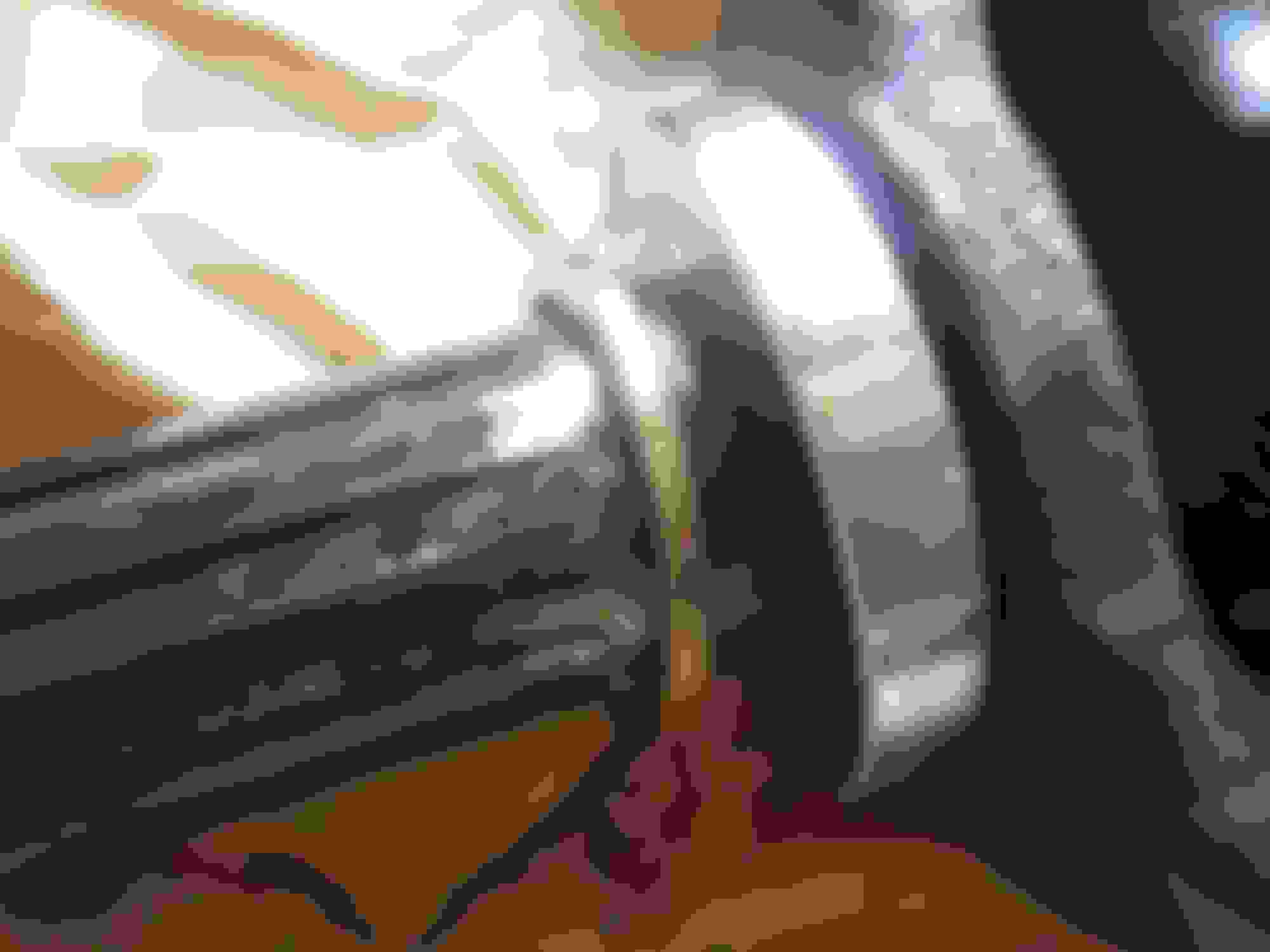
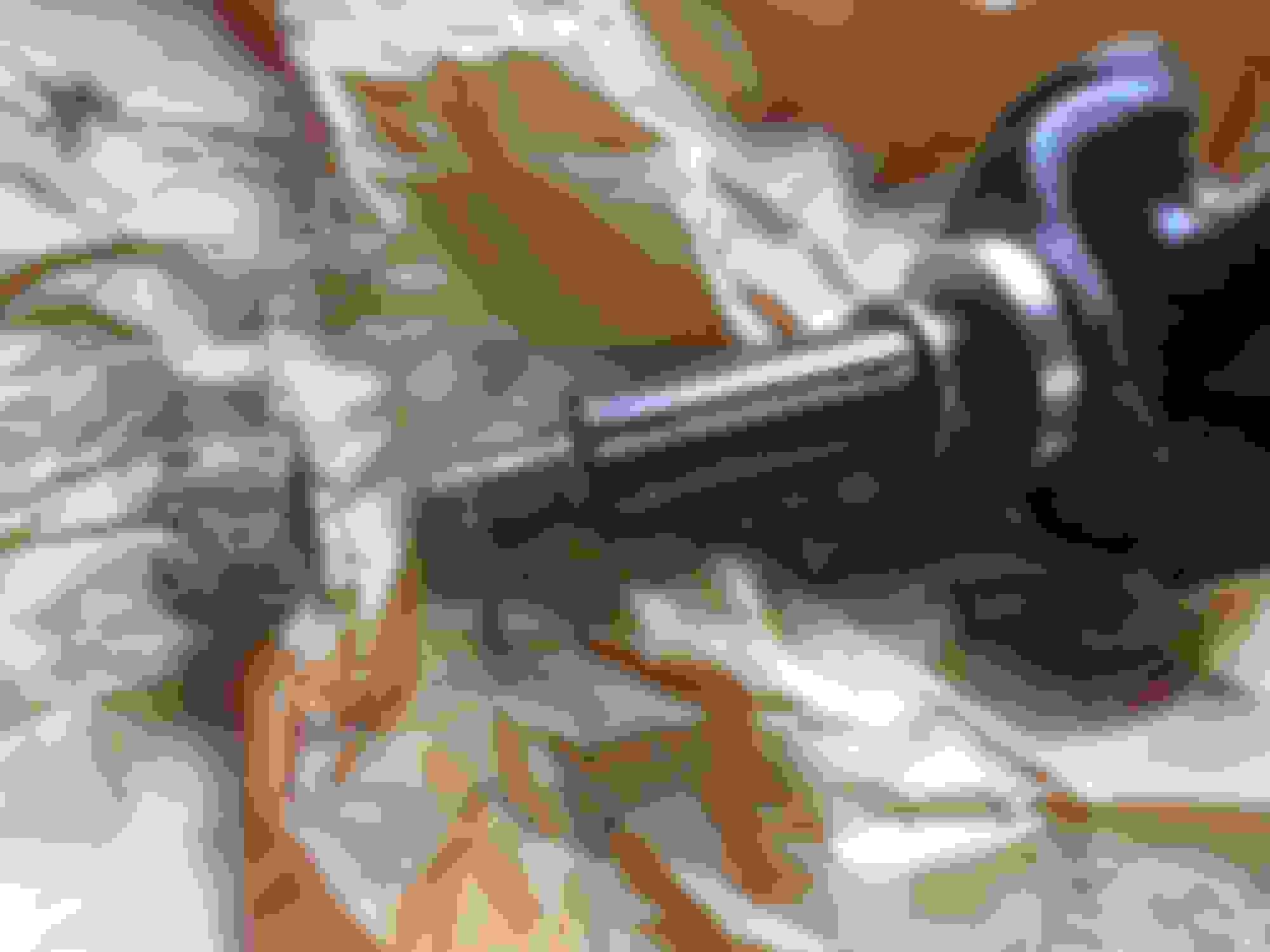
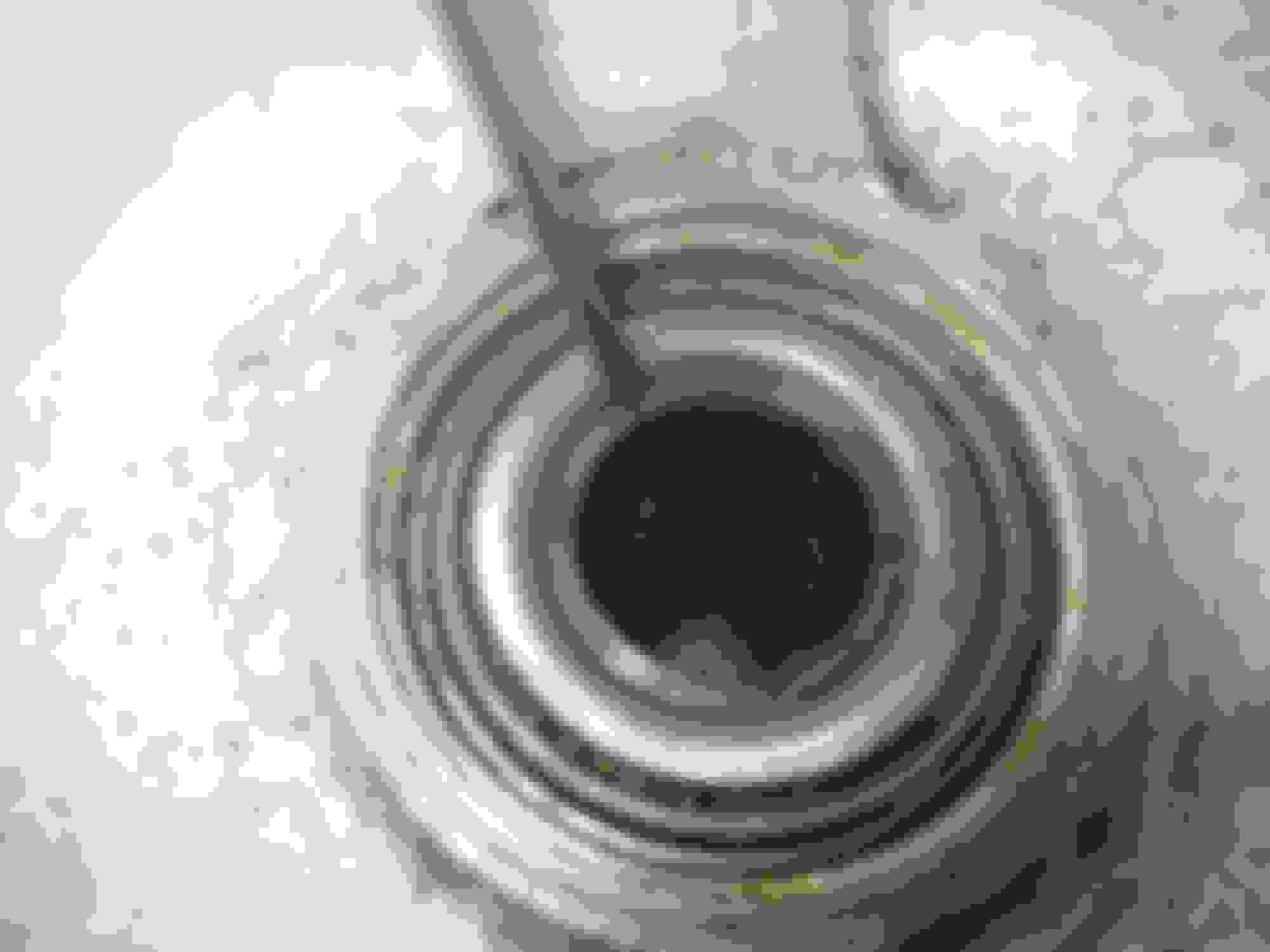
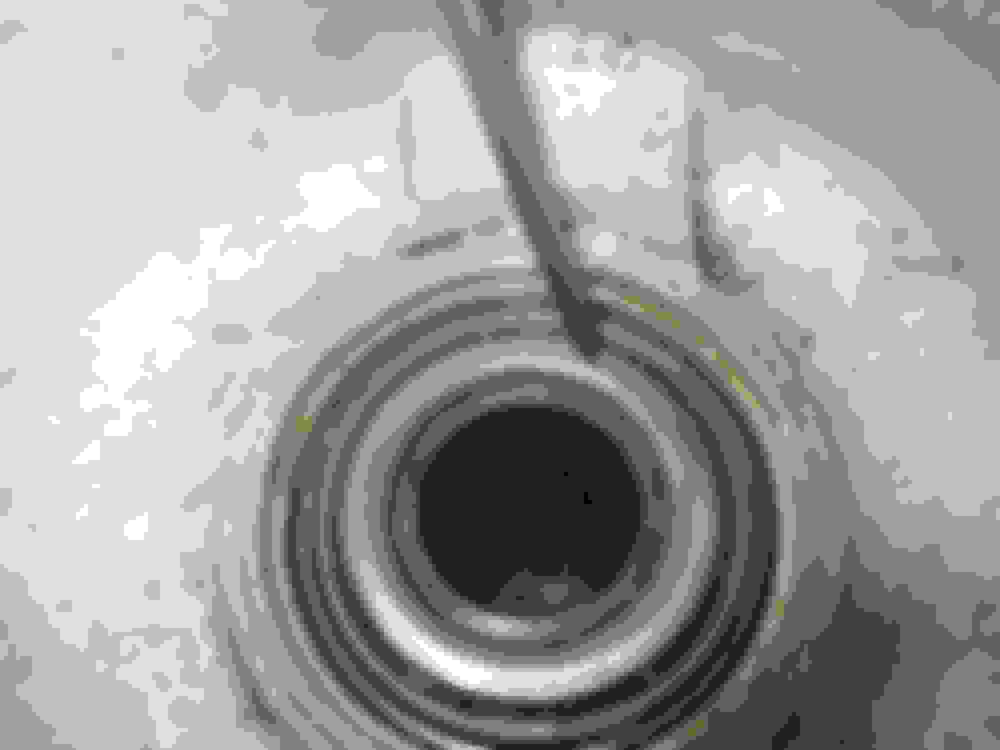
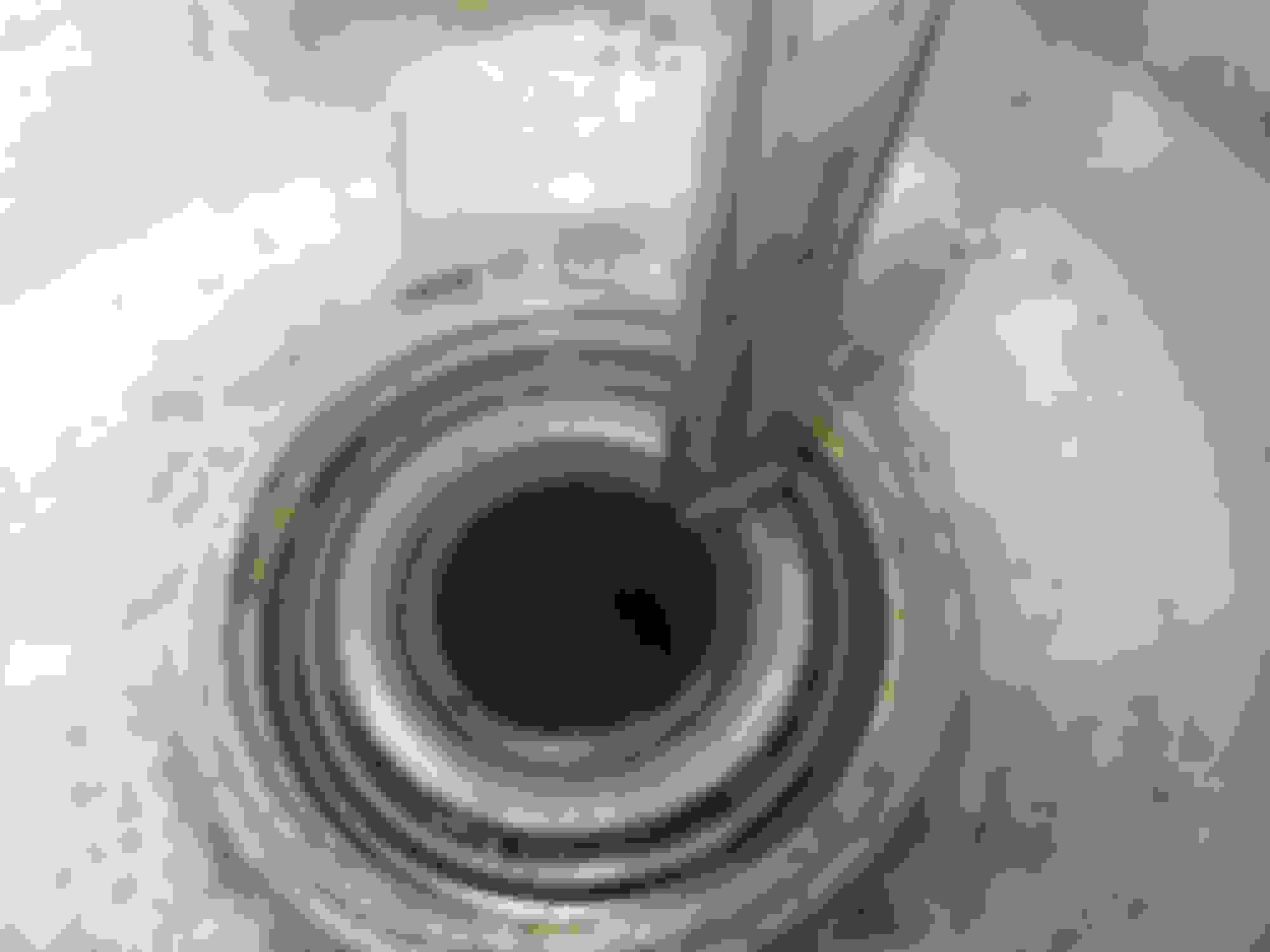
I delayed answering your question until now. there was no discernable binding or rough spots on the UJs before I removed them, which I did this morning.
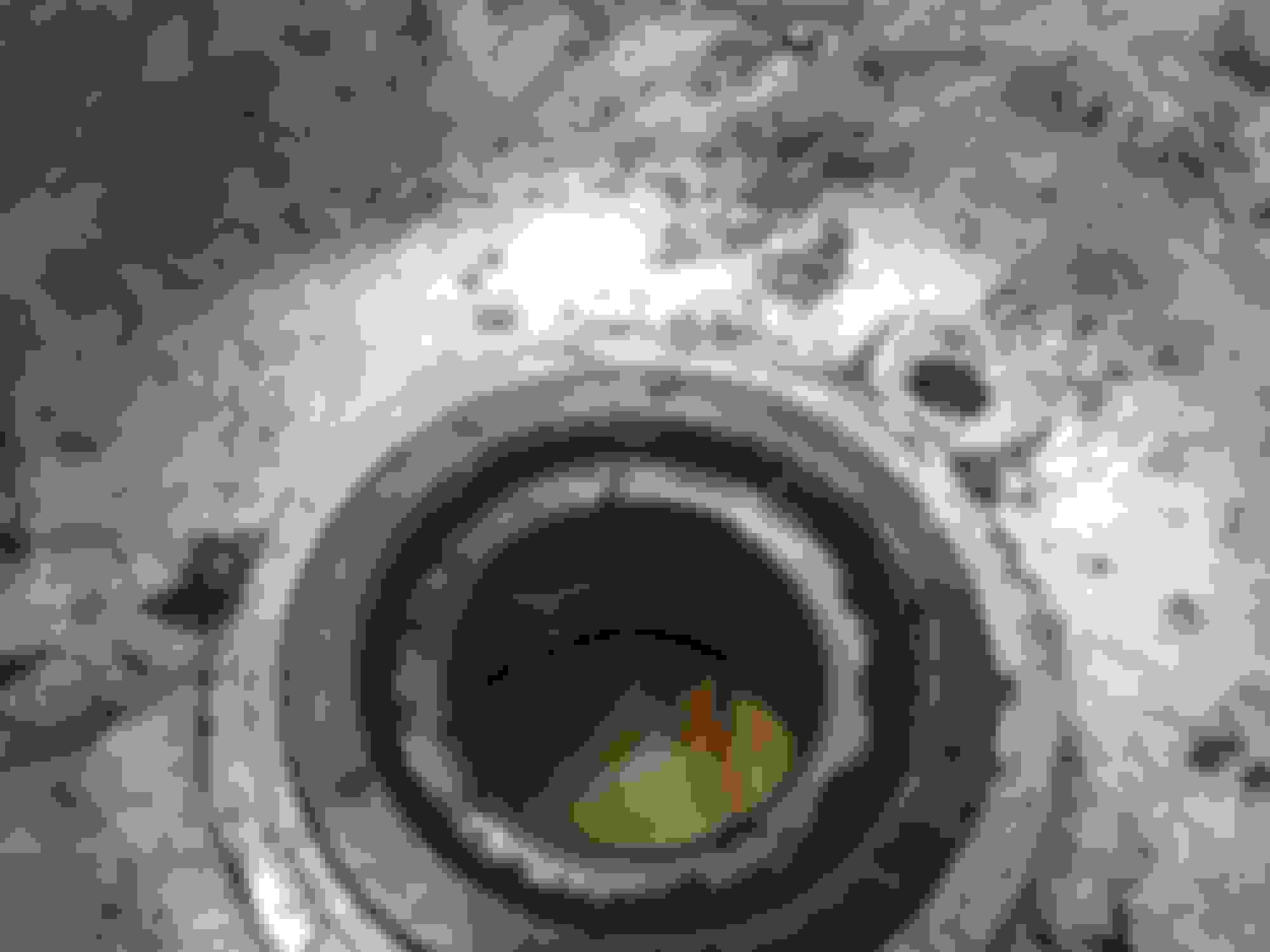
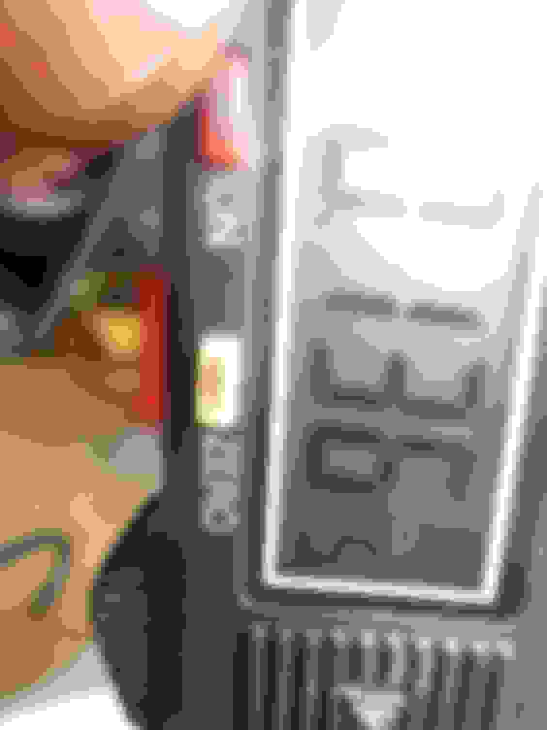
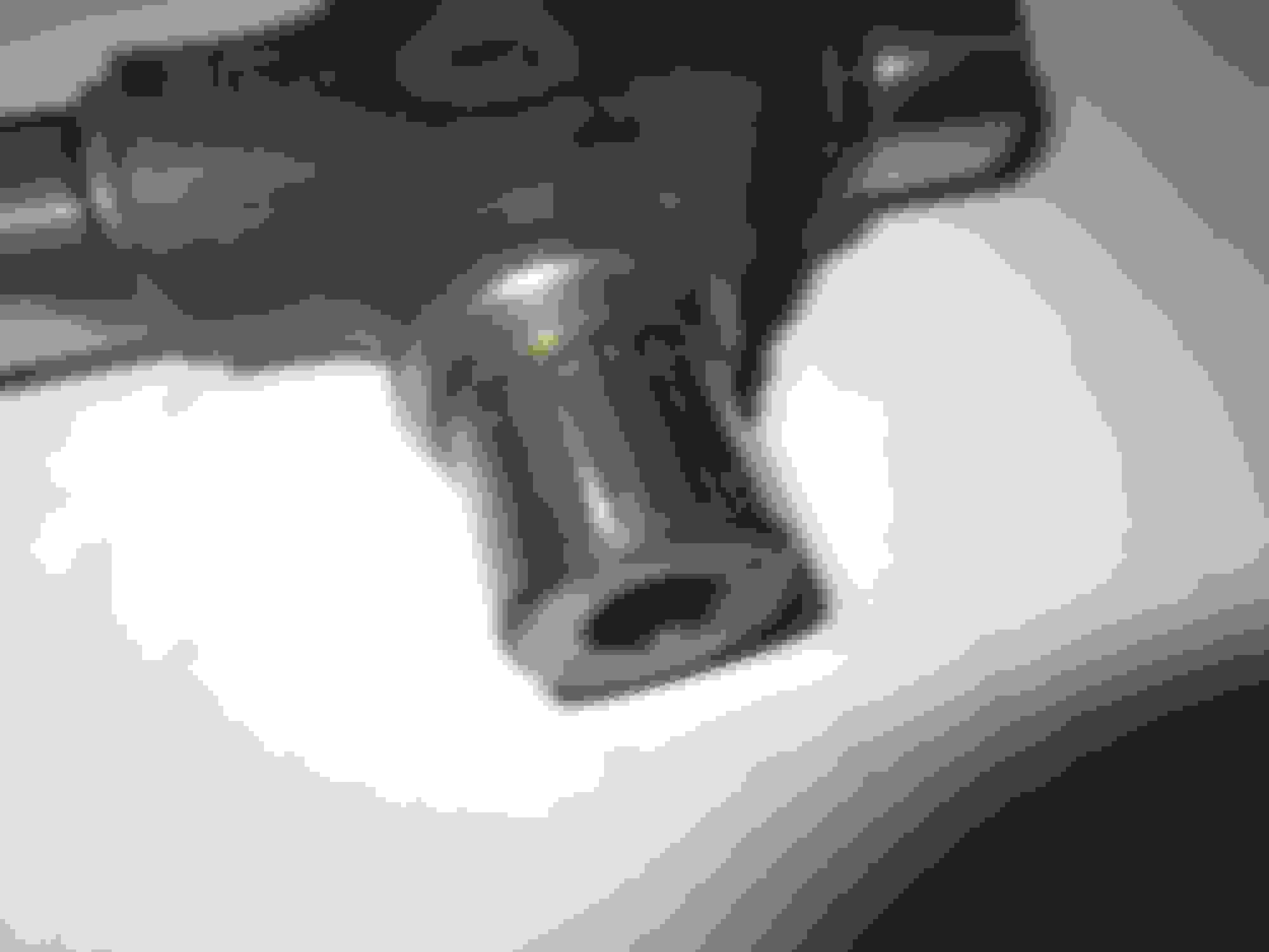
The photos show what I have found. All the UJ crosses had witness marks here and there, but the UJ nearest the diff had actual indentations you can run your nail across and make a noise! Furthermore, if you look carefully at th last two pics, you can see that the striations are not quite at parallel to the line of the UJ!
So I have definitely found something that could account for vibration under load. So we will see if it gets cured!
Doug,
I delayed answering your question until now. there was no discernable binding or rough spots on the UJs before I removed them, which I did this morning.
The photos show what I have found. All the UJ crosses had witness marks here and there, but the UJ nearest the diff had actual indentations you can run your nail across and make a noise! Furthermore, if you look carefully at th last two pics, you can see that the striations are not quite at parallel to the line of the UJ!
So I have definitely found something that could account for vibration under load. So we will see if it gets cured!
Greg said -++- "The correct endfloat for the rear hub bearings is between 2 thou float and 2 thou preload, with the ideal being zero. I understand, and am open to correction, it must be set by assembly without the spacer, measurement , of the float and then the purchase and fitment of the required spacer to give the correct final result."
plain and simple,,,, what does this mean???
endfloat? float? preload?
I'm sure you busy and don't need to be doing a ton of writing right now,,, but if ya get a spare few minutes. And, if you can't answer, that's perfectly okay...
JJJ, no bother, and thanks for asking, that is the whole point of this friendly forum. So I would explain it as follows:
If a rotating assembly is being tightened up and held in place by a nut on the end of it (eg a front wheel bearing on a stub axle, or a crankshaft, or a rear hub etc etc) it is obviously possible to so tighten up the nut that you jam the rotating parts together so they will not turn at all. Similarly, if the nut holding it all together is so loose everything flops about, the rotating assembly will shake itself to bits.
So engineers calculate, according to the design of the bearings, thermal expansion etc etc, the required tightness. Now, in reality in engines and turbines and other things of this nature, "tightness" and "looseness" really means very small tolerances of a few thou (as in 0.001 of an inch or less, although modern engineers work in hundredths of millimeters). If an assembly is required to be just a few thou "loose" (ie it can be moved along it axis forward or back a few thou) it it said to have "end float". If on the other hand, it is required to be just a few thou tight, it is said to have "preload".
The example: The rear hub consists of a rotating steel hub that rides on two large taper roller bearings which are set into the aluminium outer you see when you remove the rear wheels - this outer part is called the "hub carrier". The hub carrier is held in place by the bottom wishbone and by the driveshaft that goes into the hub and turns it. Into the centre of this hub are machined splines, which mesh with splines in the driveshaft - which is how the rear wheels are given drive by the engine. The engine turns the driveshafts and the splines turn the hubs and the wheels turn because they are bolted to the hub. The hub, remember, is set into the ally hub carrier which does NOT rotate. The bearings between the hub and the carrier allow the hub to rotate but the carrier to remain still. The driveshaft does not come out of the hub because there is a huge castellated nut on the end of it - with a split pin though it for safety - holding the entire assembly together! You see this in the centre of the hub when you remove a rear wheel.
If this is clear, you will realise we have described a classic example of a rotating assembly: too tight on the nut and the assembly will jam, too loose and it will shake itself apart! That castellated nut must be done up so that there is between 2 thou of endfloat and 2 thou of preload; then the rotating assembly will work properly. Zero endfloat is no preload and no end float.
In the case of the Jaguar rear hub because for safely that castellated nut must be done up really tight, they have a system of (in effect) "packing washers" which come in various thicknesses - these are called "spacers". The correct spacer, when inserted into the assembly, will allow the nut to be tightened up to "full grunt" and yet the endfloat/preload will remain correct. In effect the spacer makes a block on overtightening the assembly.
Now, obviously endfloat can be measured after the assembly is assembled. You just use a dial gauge and pull and push the assembly in and out. With preload, by definition there is nothing to measure as the system is tight. So to set preload: (a) you deliberately assemble the system so it is loose (ie without any spacers at all) and measure the endfloat. (b) Say you measure 15 thou of endfloat and you want 2 thou of preload: (c) you take the assembly apart, insert a spacer of 17 thou and voila! when tightened the assmebly will have 2 thou of preload.
Cheers
greg
Last edited by Greg in France; 11-20-2019 at 01:35 PM.
JJJ, no bother, and thanks for asking, that is the whole point of this friendly forum. So I would explain it as follows:
If a rotating assembly is being tightened up and held in place by a nut on the end of it (eg a front wheel bearing on a stub axle, or a crankshaft, or a rear hub etc etc) it is obviously possible to so tighten up the nut that you jam the rotating parts together so they will not turn at all. Similarly, if the nut holding it all together is so loose everything flops about, the rotating assembly will shake itself to bits.
So engineers calculate, according to the design of the bearings, thermal expansion etc etc, the required tightness. Now, in reality in engines and turbines and other things of this nature, "tightness" and "looseness" really means very small tolerances of a few thou (as in 0.001 of an inch or less, although modern engineers work in hundredths of millimeters). If an assembly is required to be just a few thou "loose" (ie it can be moved along it axis forward or back a few thou) it it said to have "end float". If on the other hand, it is required to be just a few thou tight, it is said to have "preload".
The example: The rear hub consists of a rotating steel hub that rides on two large taper roller bearings which are set into the aluminium outer you see when you remove the rear wheels - this outer part is called the "hub carrier". The hub carrier is held in place by the bottom wishbone and by the driveshaft that goes into the hub and turns it. Into the centre of this hub are machined splines, which mesh with splines in the driveshaft - which is how the rear wheels are given drive by the engine. The engine turns the driveshafts and the splines turn the hubs and the wheels turn because they are bolted to the hub. The hub, remember, is set into the ally hub carrier which does NOT rotate. The bearings between the hub and the carrier allow the hub to rotate but the carrier to remain still. The driveshaft does not come out of the hub because there is a huge castellated nut on the end of it - with a split pin though it for safety - holding the entire assembly together! You see this in the centre of the hub when you remove a rear wheel.
If this is clear, you will realise we have described a classic example of a rotating assembly: too tight on the nut and the assembly will jam, too loose and it will shake itself apart! That castellated nut must be done up so that there is between 2 thou of endfloat and 2 thou of preload; then the rotating assembly will work properly. Zero endfloat is no preload and no end float.
In the case of the Jaguar rear hub because for safely that castellated nut must be done up really tight, they have a system of (in effect) "packing washers" which come in various thicknesses - these are called "spacers". The correct spacer, when inserted into the assembly, will allow the nut to be tightened up to "full grunt" and yet the endfloat/preload will remain correct. In effect the spacer makes a block on overtightening the assembly.
Now, obviously endfloat can be measured after the assembly is assembled. You just use a dial gauge and pull and push the assembly in and out. With preload, by definition there is nothing to measure as the system is tight. So to set preload: (a) you deliberately assemble the system so it is loose (ie without any spacers at all) and measure the endfloat. (b) Say you measure 15 thou of endfloat and you want 2 thou of preload: (c) you take the assembly apart, insert a spacer of 17 thou and voila! when tightened the assmebly will have 2 thou of preload.
Cheers
greg
Damn!!!
Thank you for that.
I get it,,, we'll see (someday) if I actually "got" it, lol...
how did you go getting these uni's out ..... well worth a share ..? .... these are the same as the ones i removed with the raised section for the grease nipple ... a total PIA to remove .... !
also suprised these uni's were not causing a lot more grief considering the condition they are in ... !
Darren
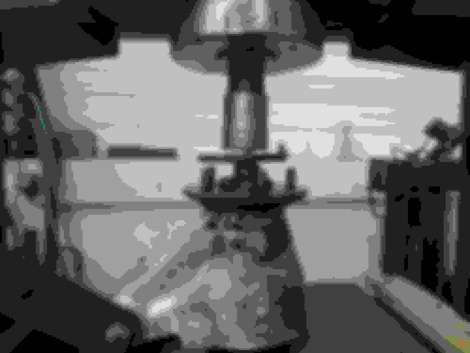
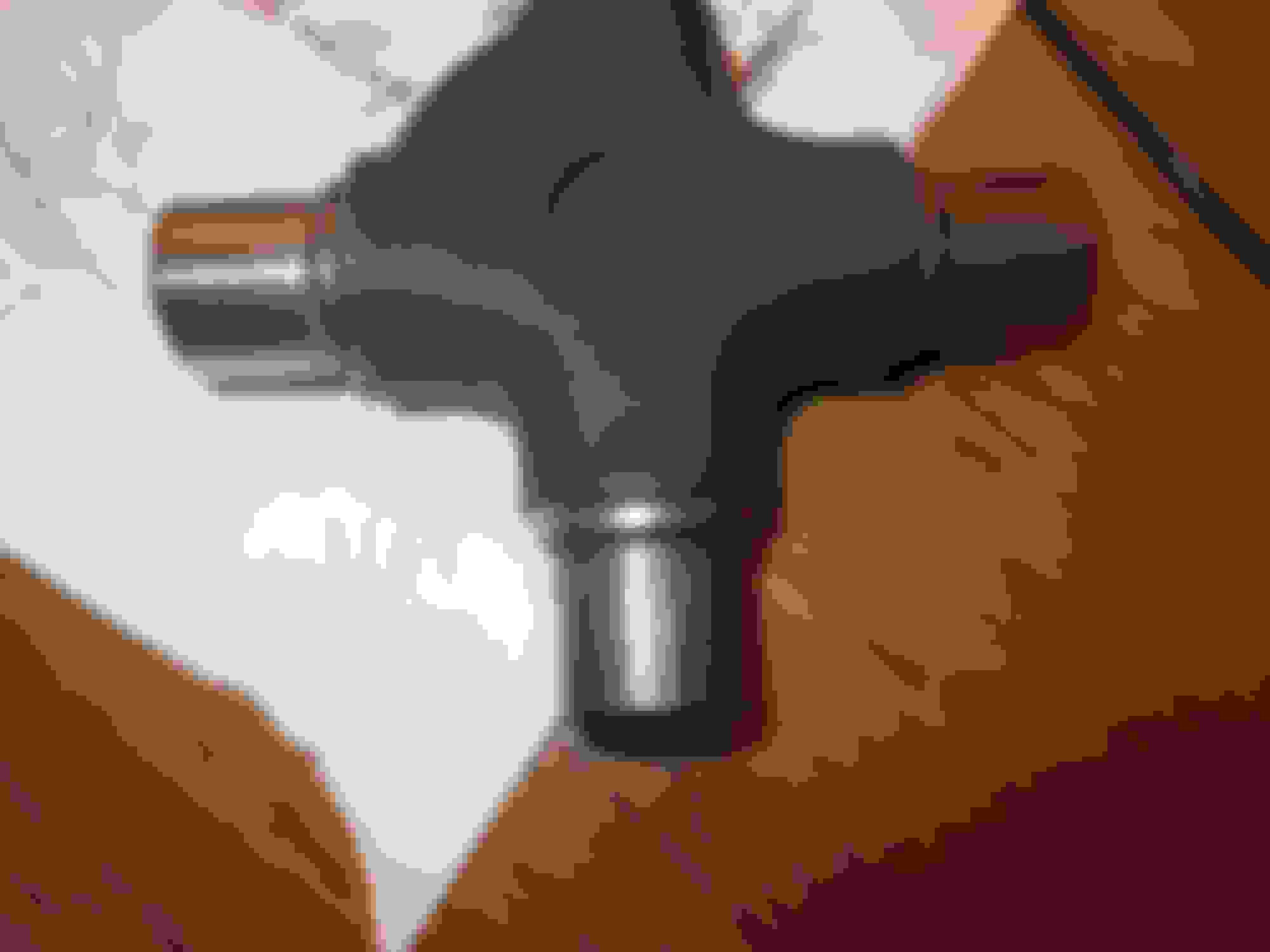
I used one of these:
The cup would not always press right out, because the UJ body stopped the pushing, so i stuck the pushed out cup end into the vice and moved the driveshaft back and forth and the cup came out.
I'm all over it... Thank you!
I got skerd and avoided this when I dropped the back axle... And, UJ, which I really wanted to attempt. I need a better work space, or one at all. Crazzzzy!
So,,, for the inner bearing,,, the spacer goes BETWEEN the inner bearing and the rider? The rider being the separator,,, between the drive shaft and the "wheels" of the inner bearing... I'm not sure why the spacer would be placed BETWEEN the rider and the inner bearing...?
EDIT --- OhOh! Wait! I think I get it... That spacer (can the old one simply be reused?) is what produces the controlled "play" in the carrier assembly? And it is BETWEEN the rider and the bearing to give it? Does he call it a RIDER or a race,,, in the video?
The order is as follows:
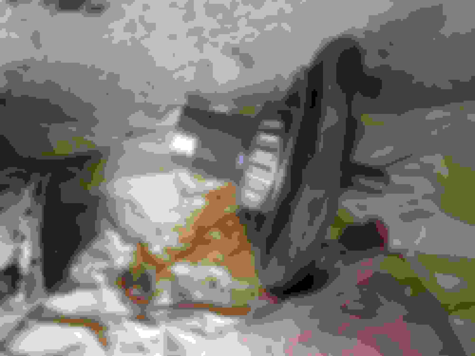
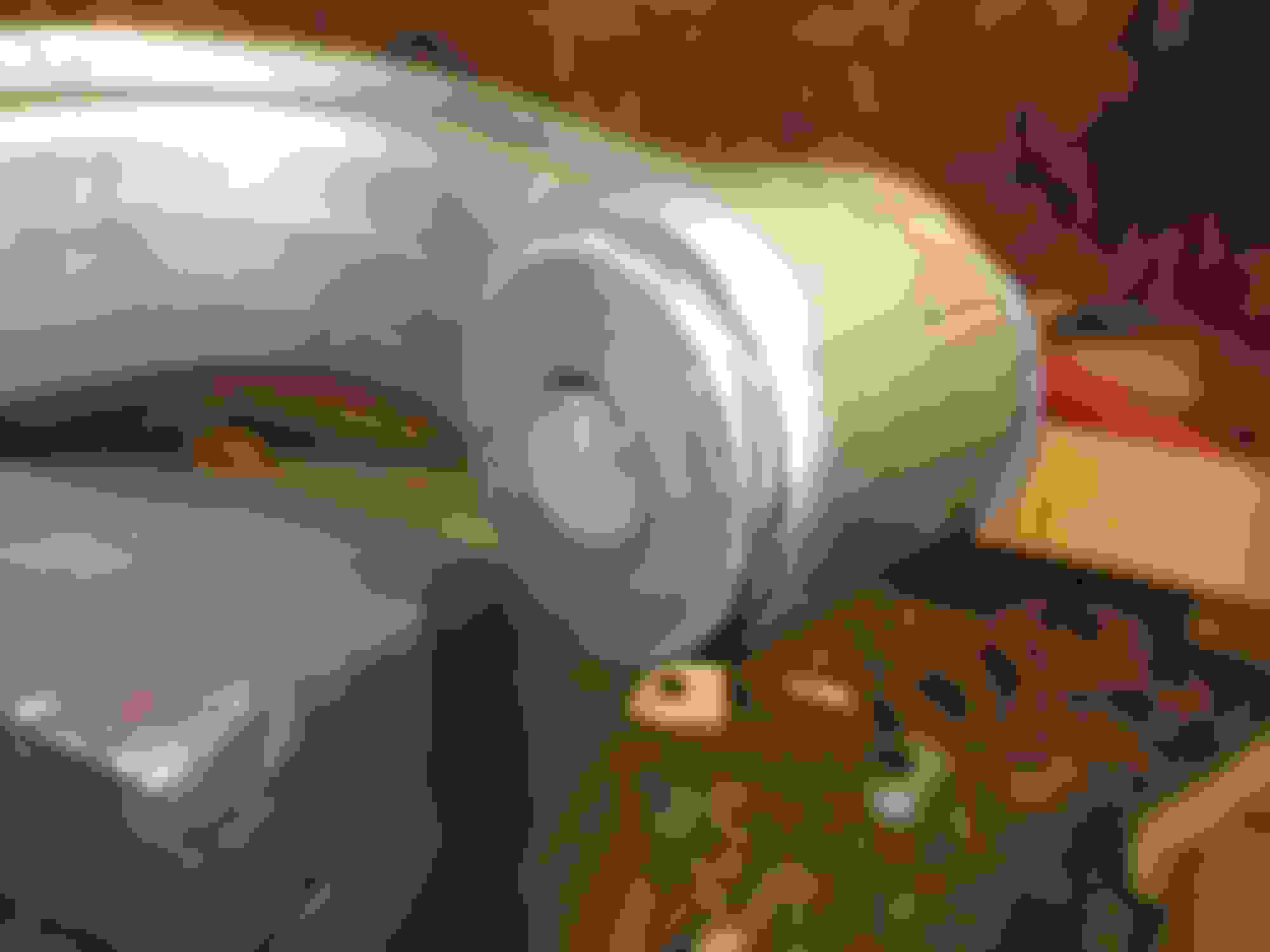
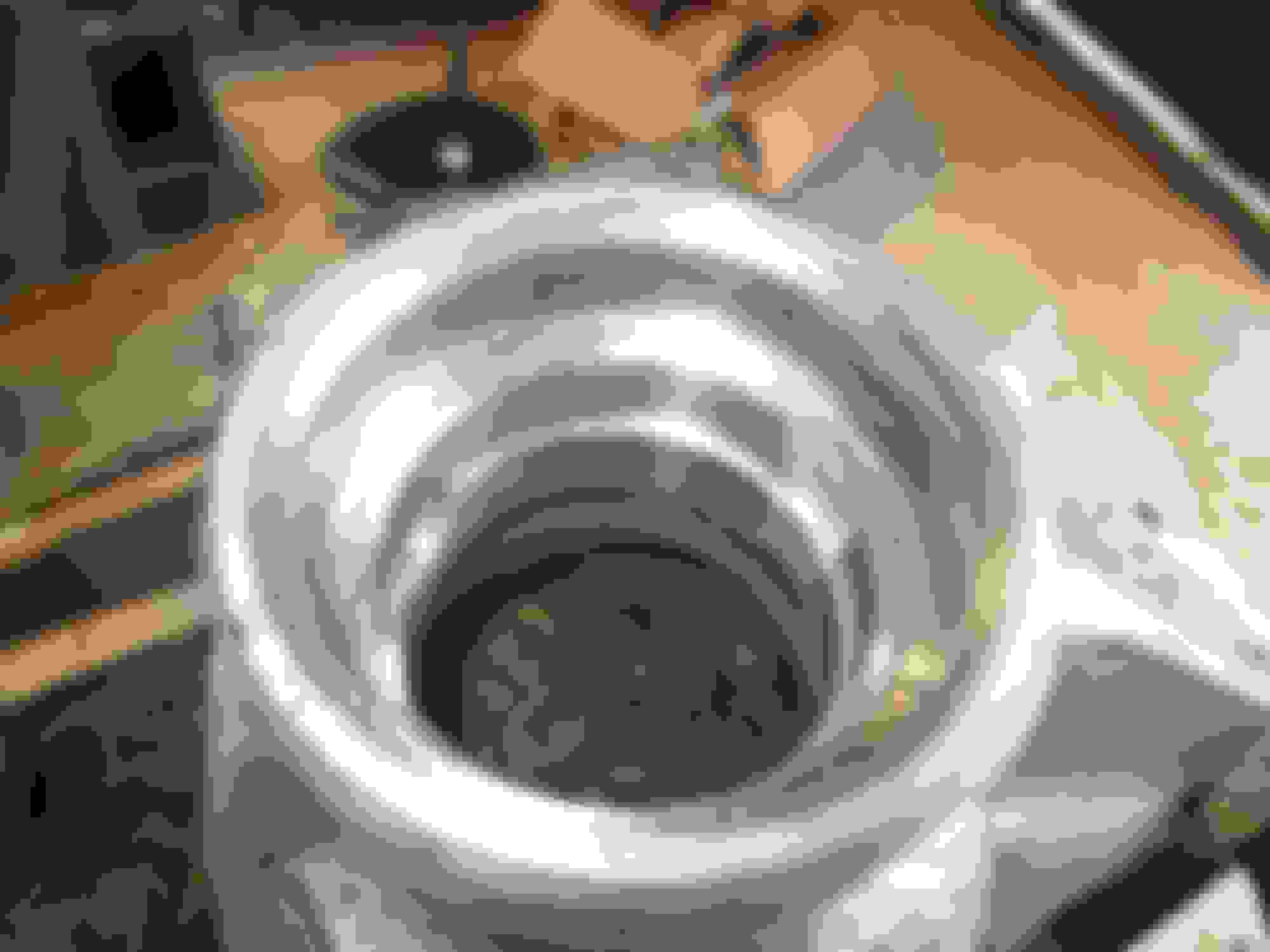
Start with the splined end of the driveshaft. Onto it goes a thick stainless spacer that is common to all cars. Next comes, as you say, the special phosphor-bronze spacer that is available in various thicknesses - this is the one used to set the endfloat. Then this lot is pushed into the hub which itself has been pushed into the carrier. In this photo, on the left you see the splined end with the stainless and then the P-B spacers, then on the right you see the hub which has been pulled out of the carrier. On assembly the hub is pushed into the carrier, and the splines are pushed into the hub.
When you do up the castellated nut on the outer end of the hub, the P-B spacer pushes up against the tubular end of the hub, thus ensuring the splined end of the driveshaft cannot be drawn further than intended into the hub, as the spacer, jammed against the inside end of the hub, prevents it.
This second pic shows the hub in closeup. The P-B spacer rides against the end of the hub. Once the castellated nut is done up, the driveshaft cannot pull out, but equally the hub bearings cannot go any tighter together than the endfloat (or preload) that has been set, as (in effect) the nut is merely squeezing the hub end to end, once the spacer is in contact with the inner end of the hub.
The order is as follows:
Start with the splined end of the driveshaft. Onto it goes a thick stainless spacer that is common to all cars. Next comes, as you say, the special phosphor-bronze spacer that is available in various thicknesses - this is the one used to set the endfloat. Then this lot is pushed into the hub which itself has been pushed into the carrier. In this photo, on the left you see the splined end with the stainless and then the P-B spacers, then on the right you see the hub which has been pulled out of the carrier. On assembly the hub is pushed into the carrier, and the splines are pushed into the hub.
When you do up the castellated nut on the outer end of the hub, the P-B spacer pushes up against the tubular end of the hub, thus ensuring the splined end of the driveshaft cannot be drawn further than intended into the hub, as the spacer, jammed against the inside end of the hub, prevents it.
This second pic shows the hub in closeup. The P-B spacer rides against the end of the hub. Once the castellated nut is done up, the driveshaft cannot pull out, but equally the hub bearings cannot go any tighter together than the endfloat (or preload) that has been set, as (in effect) the nut is merely squeezing the hub end to end, once the spacer is in contact with the inner end of the hub.
Greg, again, many many thanks...
By George I think I've got it! Really!
I have shocks and springs on my list and thanks to the leads that you all have provided, I think they will be within financial reach soon. I am thinking, for good measure (not ok mowing the state of any of the mechanicals on Cherry) shock time might be the right time for the bearings at the axle, in the carrier, and the UJ, as well. Feeling more confident everyday.
Driveshaft splined-part threaded end: threads recut by my friend Louis the Lathe King (Louis Roi des tours) on account of how the 32 tonnes bowed out the threaded part a bit, in spite of the nut being fully on the threads!
Hub and driveshaft splined-part soaked in 70% phospohoric acid and all rust dissolved, splines dressed a touch with typewriter files (under 50s google it!) and smooothed with 1200 grit. Splines now slide together with a small easy push.
Bearing race on wheelnut end of hub pulled off with wonderful bearing separator tool - 20 quid bargain.
New bearing race wound onto hub. Pics attached
To do later in the week: outer bearing races into hub carrier; hub into carrier; inner race into hub carrier; measure end float distance and adjust if needed.
Once end float satisfactory, install new UJs and finally assemble driveshaft and hub and refit to car!.
i had some odd vibrations at 1st drives , so to reduce some rotating mass , i went to a single Aluminum driveshaft, much lighter weight,(less weight less vibrations) and using GM HD U-joints with sliding yoke GM !
to each his own way!
ron
 11-19-2019, 03:48 AM