When you click on links to various merchants on this site and make a purchase, this can result in this site earning a commission. Affiliate programs and affiliations include, but are not limited to, the eBay Partner Network.
i had some odd vibrations at 1st drives , so to reduce some rotating mass , i went to a single Aluminum driveshaft, much lighter weight,(less weight less vibrations) and using GM HD U-joints with sliding yoke GM !
to each his own way!
ron
What is the rough weight difference between the aluminum and the OE? Just wondering... And,,, pretty pennies???
Jay , my driveshaft is 1/3 the weight of factory, double shafts&joints, and eliminates the center bearing! so weigh your whole setup, and deduct 2/3s.
cost was $250. usd.
ron
Darren , when the jag irs cage has tires that grip, the whole cage can/will rip out of its mounts!
i know it did on mine when 1st driving , so those tubing has sphere adjustable joints and i put a slight preload ,it also tries to lift the rear of car ,and that puts more down pressure on tires(more bite), for harder accelleration! old drag race trick!
ron
Returning to my rebuild, yesterday I tried to fit the new GMB brand universal joints I had been supplied with to the axle driveshaft.
With both cups pressed in it proved impossible to fit the circlip at one end. You could just see the circlip groove - which is about 2 mm wide - in the yoke end, but the cap protruded about 1 mm too much and the circlip could not be installed. The caps' interior surfaces were hard against the trunnion ends and so no amount of pressure would have any effect.
After struggling for ages and thinking I was stupid, I consulted Grant on the France/Oz hotline. He advised me to measure the overall length of the cross piece trunnion to trunnion without the bearing caps installed, and then the overall length of the crosspiece trunnion to trunnion with the bearing caps installed.
Results as follows:
GMB crosspiece with no caps installed: 99.95 mm
OEM GKN/Spicer with no caps fitted: 99.95 mm
GMB crosspiece caps installed: 107 mm
OEM GKN/Spicer caps installed: 106.2 mm
The correct spec is an overall length with bearing caps fitted of between 106 mm and 106.4 mm. Therefore the GMB parts are incorrectly made and should be avoided. I have now ordered DANA/Spicer part DANA 514101X from Rockauto, which are made to the correct spec according to the specsheet: https://www.rockauto.com/en/moreinfo...78647&jsn=1624
This may save someone on here much grief - which the GMB part certainly caused me.
When I eventually catch up with Greg, we will be AWOL for a solid month.
No stress, beer is the answer, HA>
Followed very closely be COFFEE.
Too right. Once this is done and the Lottery organised, we will put some serious heat into the car! The Madames will have a whale of a time comparing obsessive activity notes while we are AWOL!
UJ meaurements:
I have just come in from the garage having done some careful measuring with my electronic caliper.
As follows:
Yokes: Outer machined edge to outer machined edge: 113.7 mm
Outer edge of circlip groove to outer machined edge: 2.0 mm Therefore, outer edge of circlip groove to outer edge of circlip groove = 113.7 - (2 mm x 2) = 113.7 - 4 = 109.7 mm Depth of circlips = 1.5 mm x 2 = 3 mm
So: Length available for UJ cross, caps fitted and circlip installed =109.7 mm - 3 mm = 106.7 mm
Overall length of DANA-Spicer UJs ordered from Rockauto = 106.4 mm So given my measurement tolerances, I think as long as the new UJs are to spec that they should go in OK. But the things ARE tight!
UJ meaurements: Length available for UJ cross, caps fitted and circlip installed =109.7 mm - 3 mm = 106.7 mm
Overall length of DANA-Spicer UJs ordered from Rockauto = 106.4 mm So given my measurement tolerances, I think as long as the new UJs are to spec that they should go in OK. But the things ARE tight!
The DANA-Spicer UJs from Rockauto turned up today. Unbelievably high quality parts, really impressive. AND, here is the best part, each comes with a packet of circlips in varying thicknesses, so an exact fitment can be made. DANA-Spicer part number DANA 514101X. They measured at an overall length of 106.35 mm, so I hope all will be well.
My very strong recommendation to anyone doing the rear axle driveshafts is to use these items. Link as in my post number 25 above: https://www.rockauto.com/en/moreinfo...78647&jsn=1624
Last edited by Greg in France; 12-03-2019 at 05:38 AM.
The rear axle is now in the car with new UJs and new hub bearings. I am writing a PDF of how it was done, with photos, as I hope that might be useful to have on the forum. Most particularly, I could not find any clear info about the spacers and how to measure them, and I will ensure this is clear. Meanwhile, here are a few notes and pics:
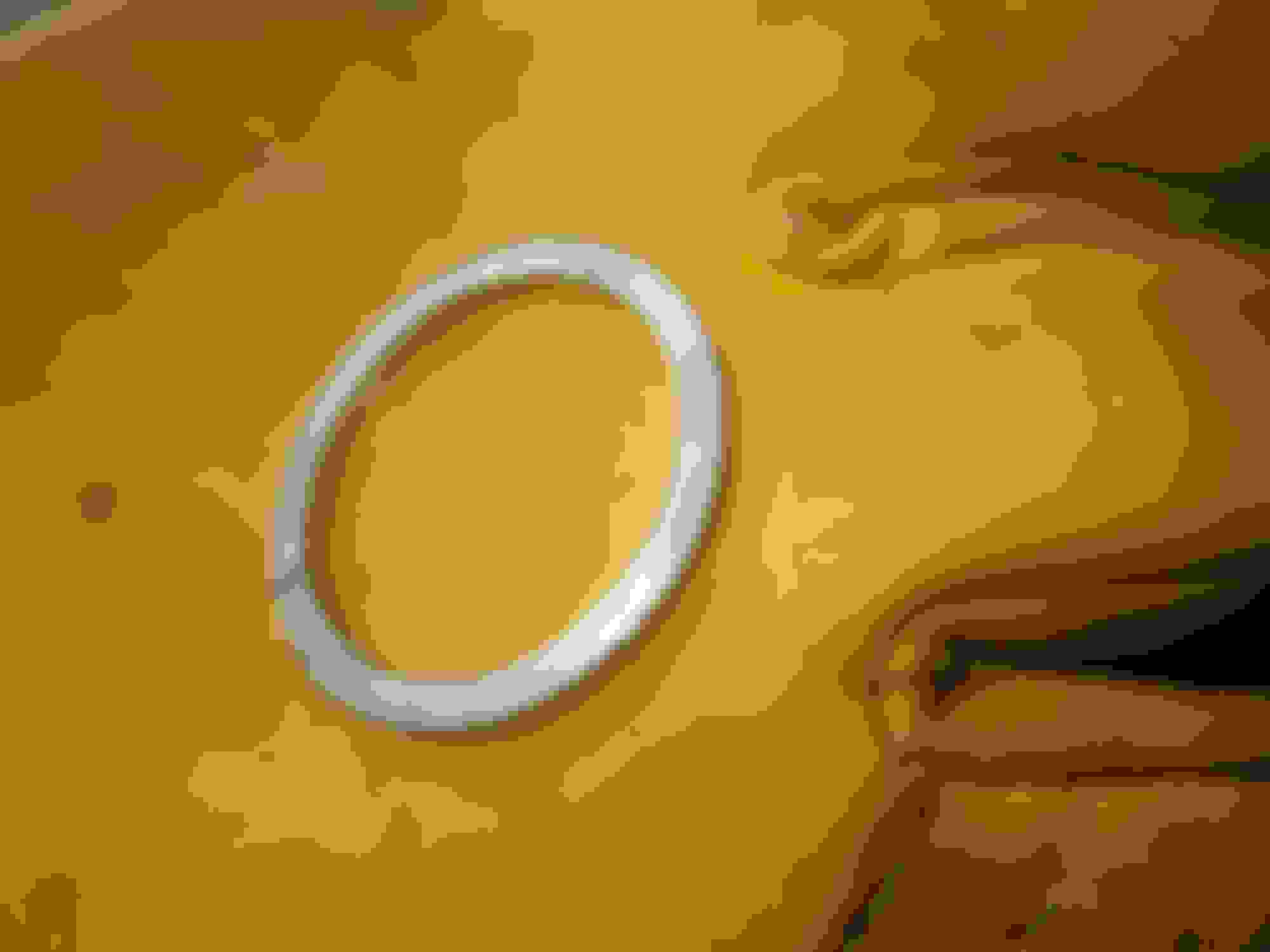
I made up this little effort to help the UJ tool sit more easily on the outer edge of the driveshaft yoke when pushing in the new UJ caps. Without it it tends to slip off. Of course you need the hole it fills when removing the old caps:
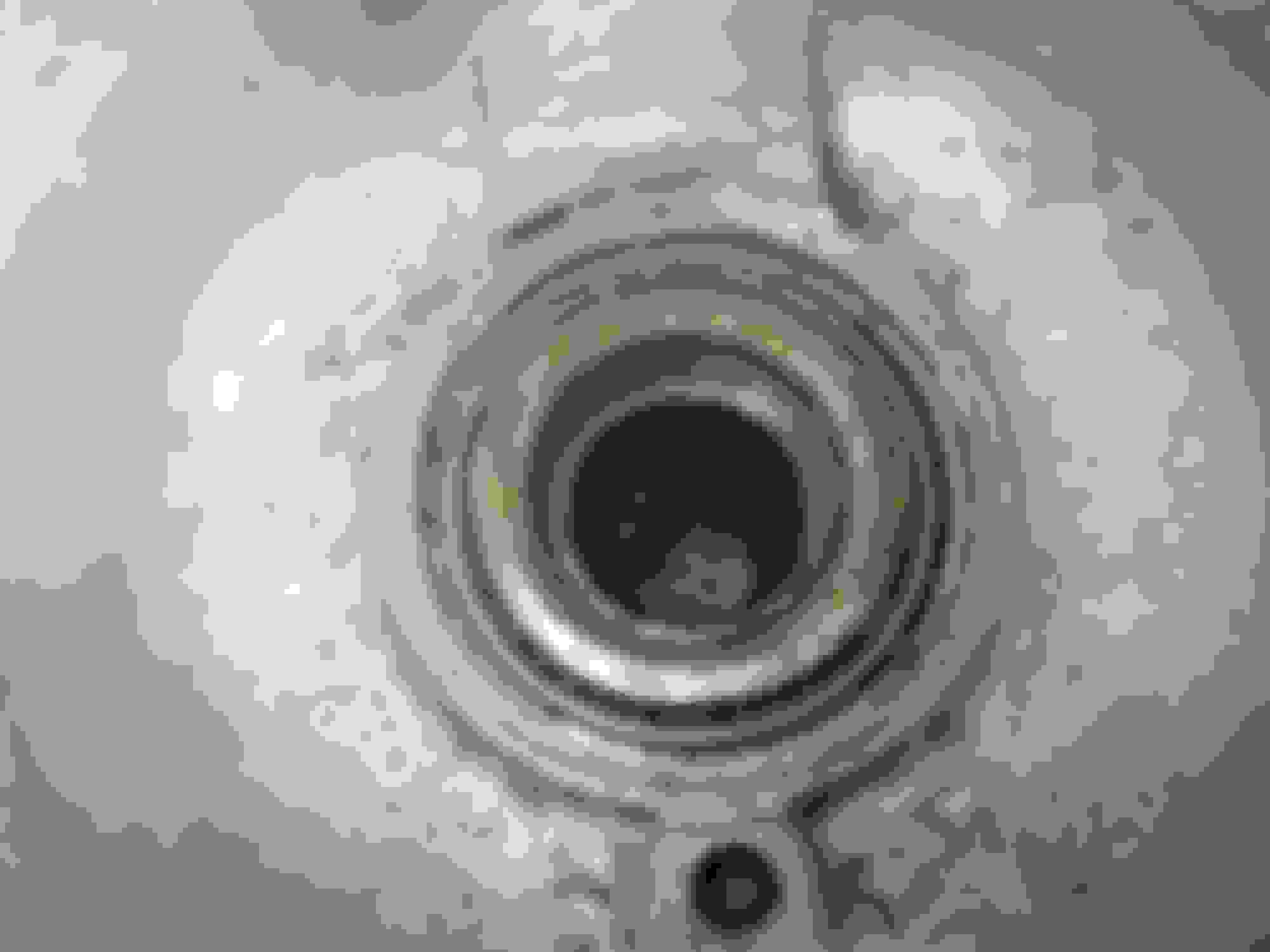
This is the hub carrier, old bearings driven out, cleaned up and ready for the new ones, and then showing the new outer bearing outer race being driven into place:
The OUTER race of the inner bearing has to be wound into place with a threaded rod, as it is shrouded by the hub carrier:
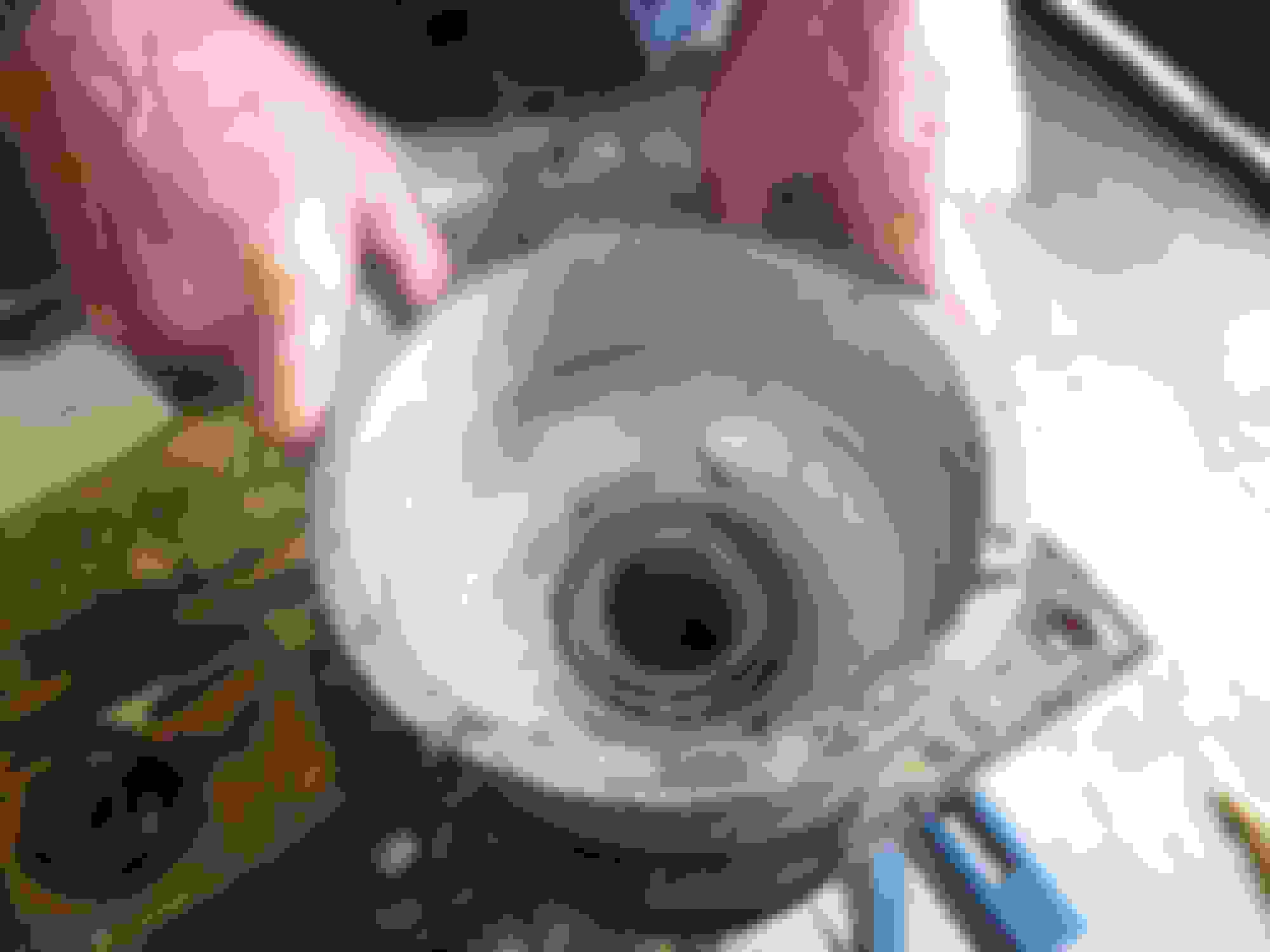
Then the inner race of the OUTER bearing has to be driven onto the hub tube:
Then insert the outer grease seal into the hub carrier, this photo also shows the two outer races in place
Now the hub with the outer bearing inner race on it, is dropped into the hub carrier so it is properly in its outer race. The assembly is then turned over and the inner race of the inner bearing is placed onto the hub tube poking through the carrier:
This inner bearing inner race is a VERY tight fit on the hub tube and needs to be wound onto it to get it sitting properly against its outer race in the hub carrier, after a few taps with a bearing driver and a hammer to get it started over the hub tube:
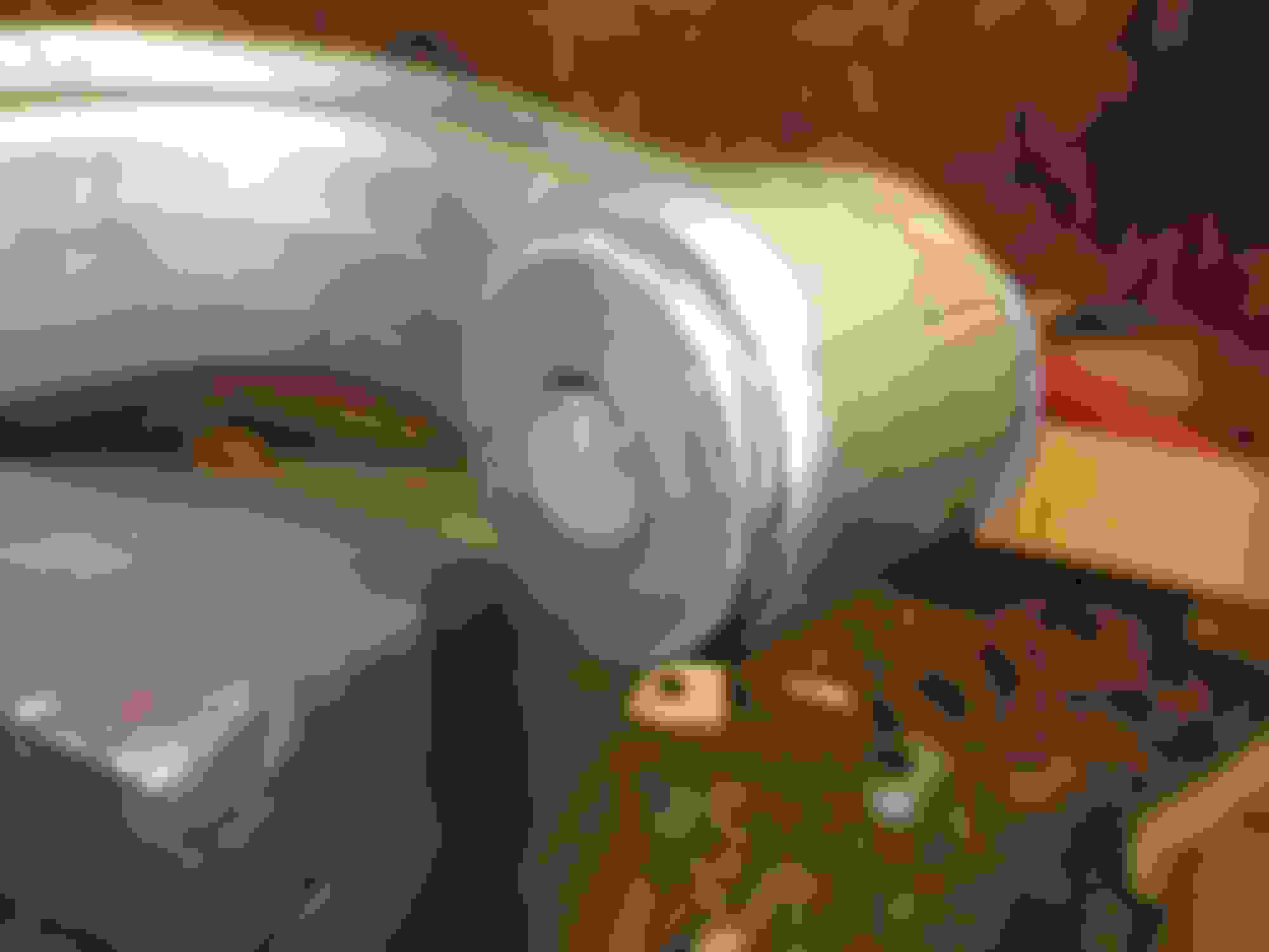
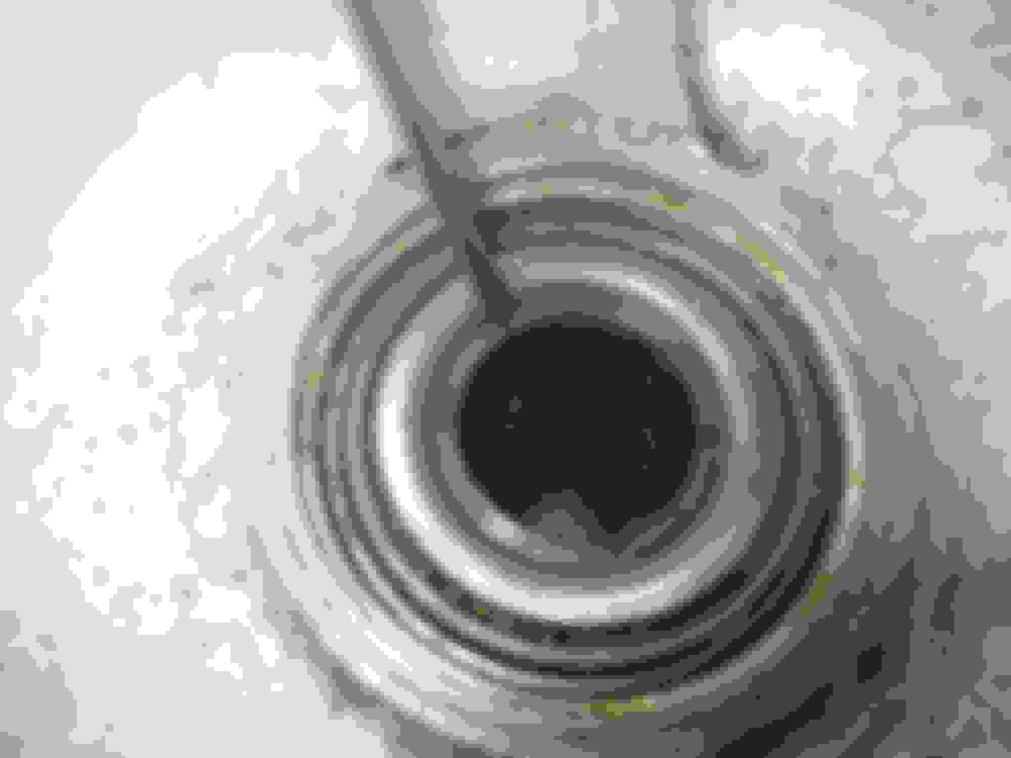
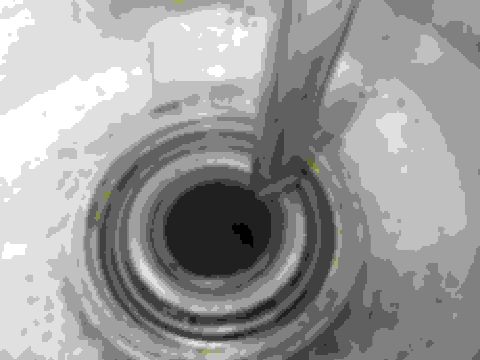
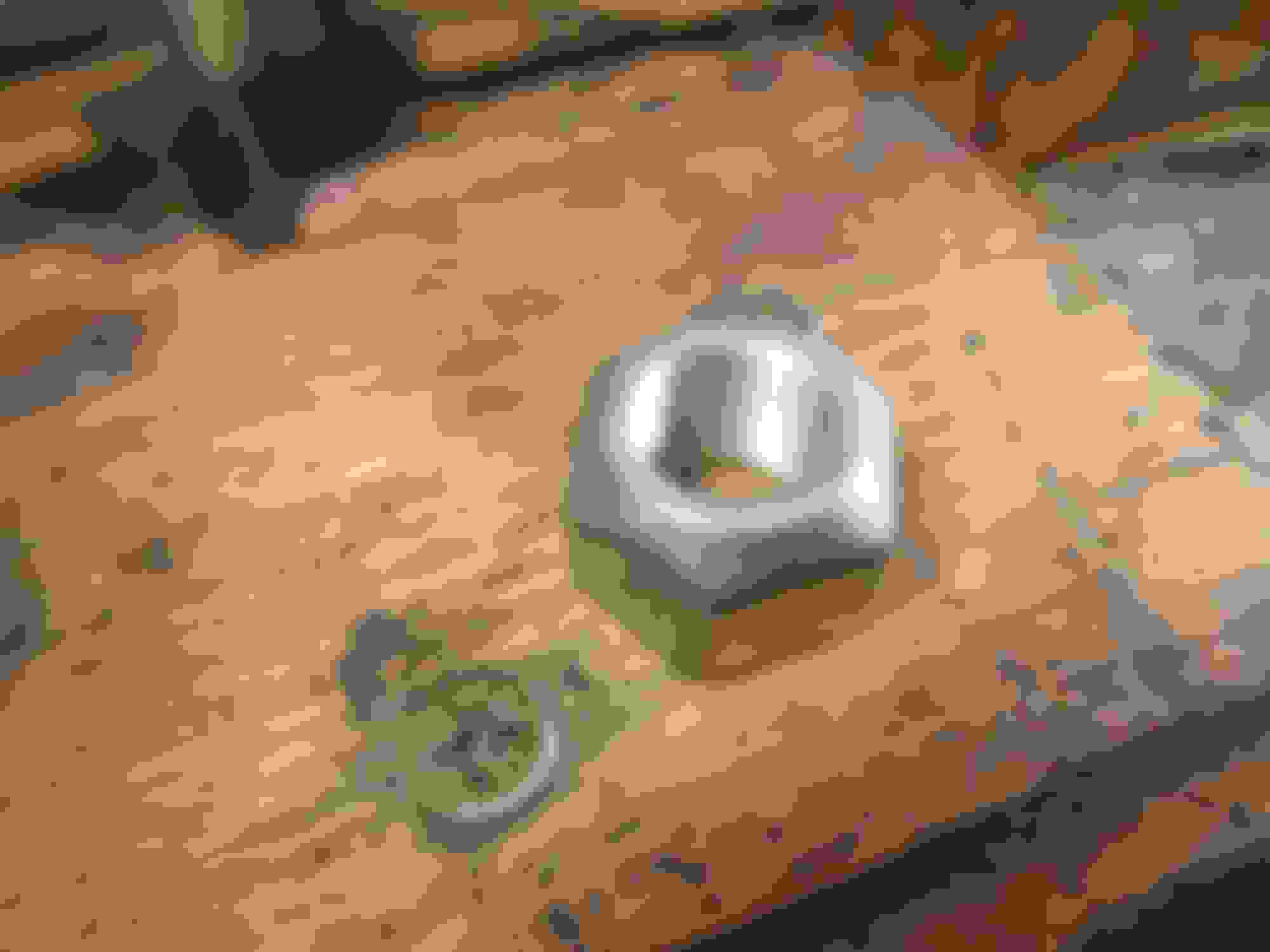
Now comes the only really tricky part: measuring the required endfloat spacer. I took two snaps of the exact bit you have to measure. It is the space between the end of the hub tube (see pointer in this snap):
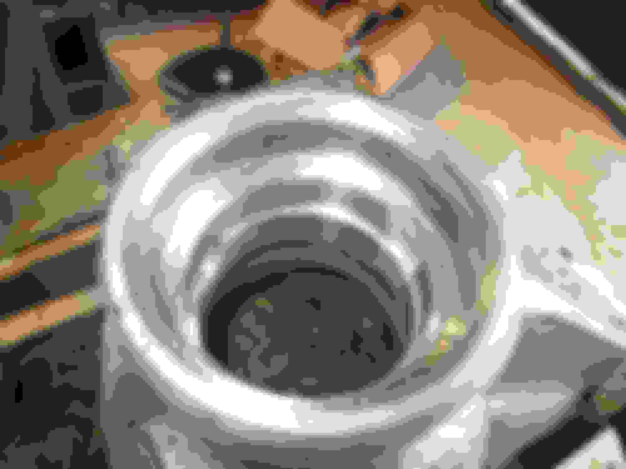
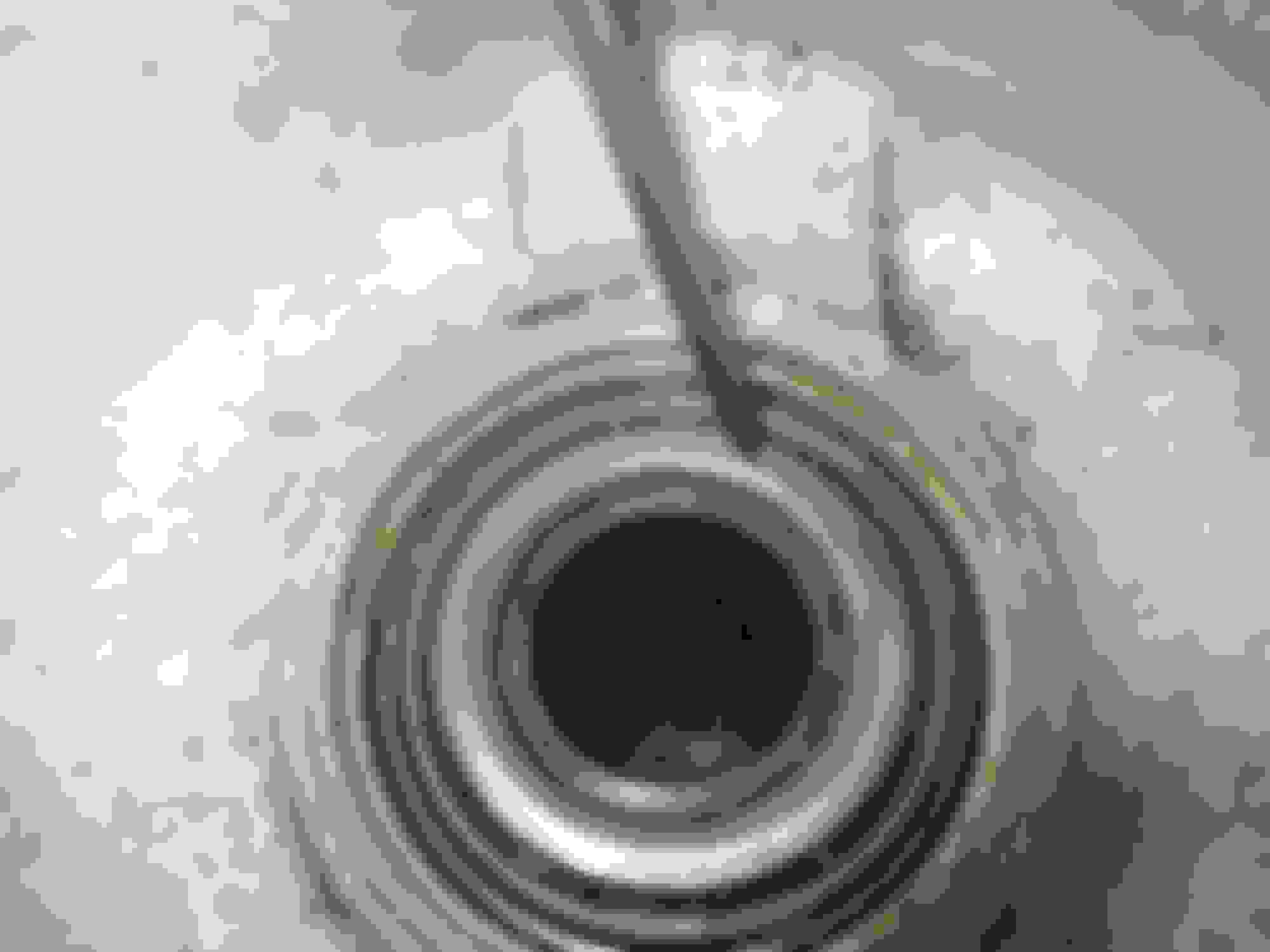
and the top of the inner bearing inner race (see pointer in this next snap). The bearing is higher than the end of the hub tube and the spacer goes in to equalise the two, so they are level, plus a couple of thou. Though actually a slight preload of 2 thou, or endfloat of 3 or 4, will be quite OK:
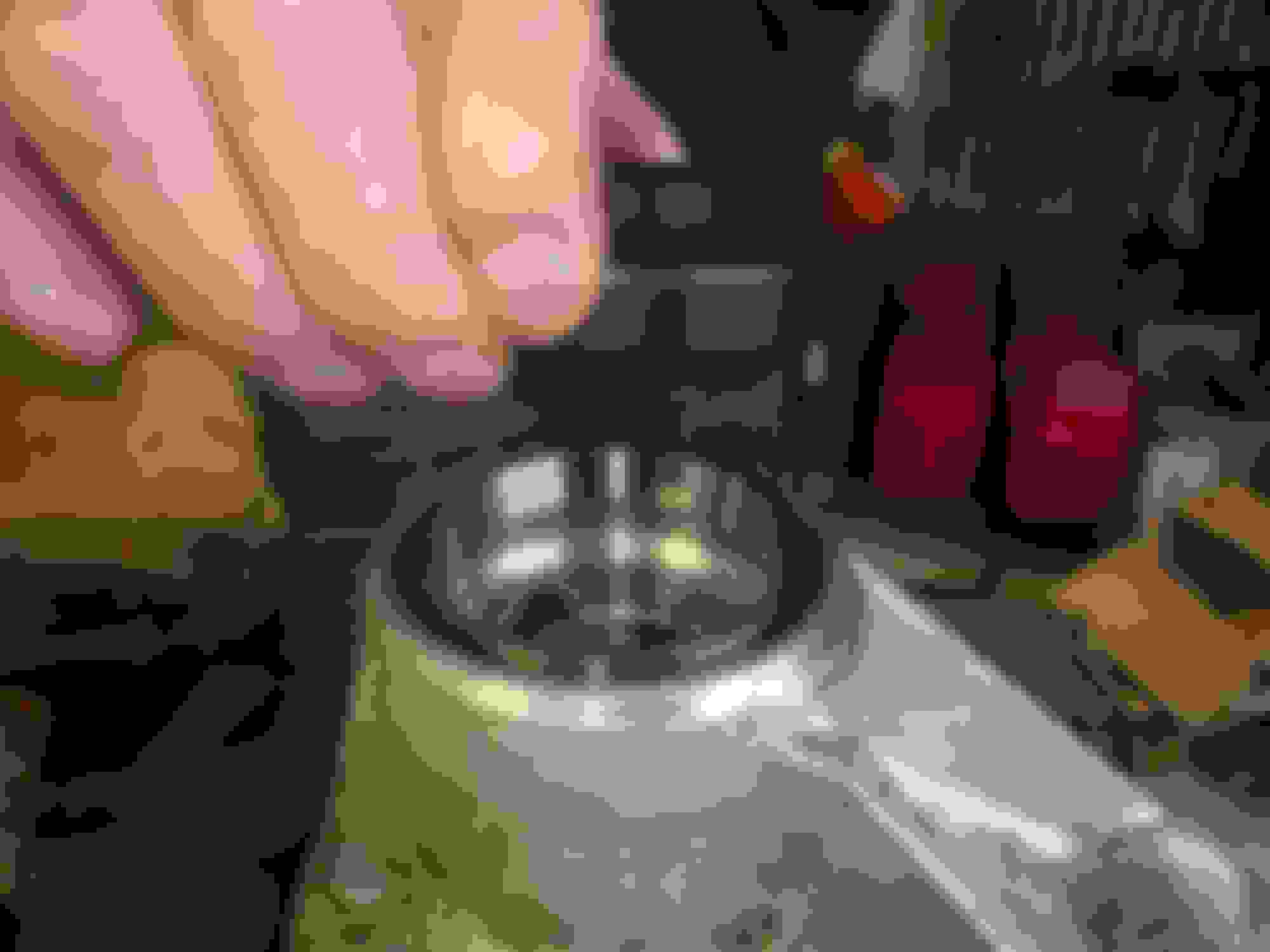
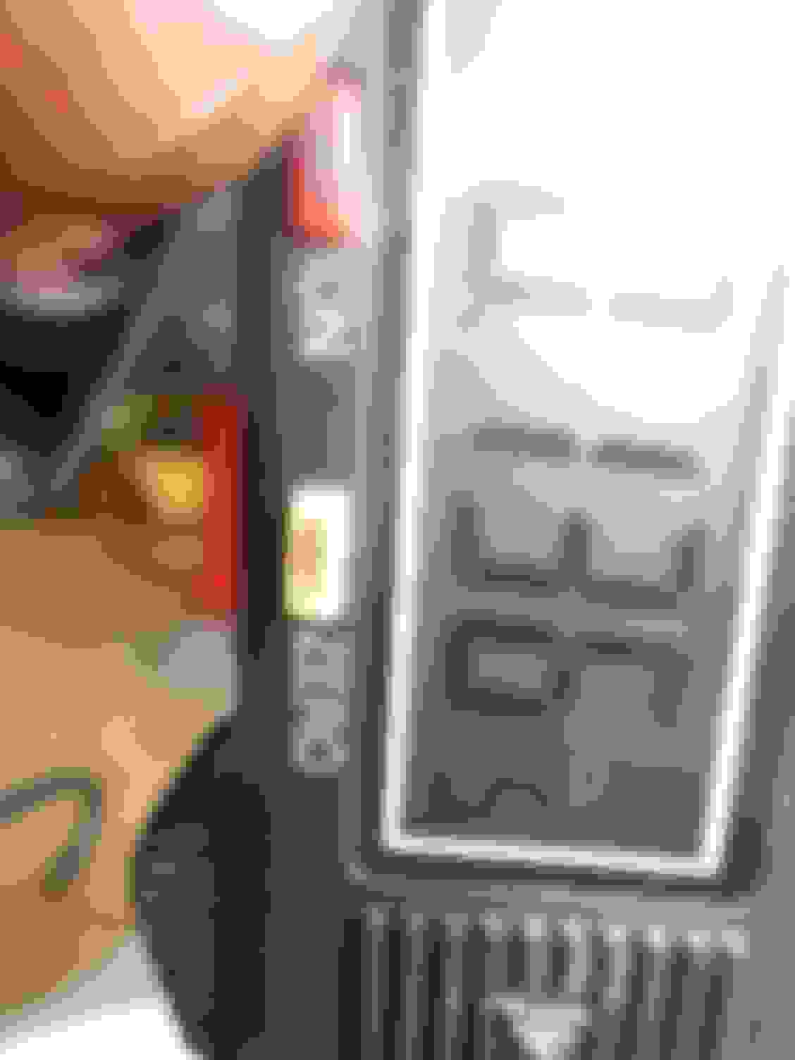
Then, using an electronic calliper thingy, measure the distance between the two. BUT BEWARE, the inner race if the bearing will need to be tapped down with a drift to ensure the measurement is the same all round the circumference of the inner race:
And here is the spacer that goes into the gap. It is actually placed on the splined part of the driveshaft when the driveshafts are being assembled into the hub. These spacers are available from SNG Barratt in all the required steps of sizes. The spacer sits on top of the hub tube and just fills the space between the top of the hub tube and the top of the bearing inner race, thus ensuring that when the driveshaft is inserted and tightened into the assembly to 140 ft llbs, the bearings are not squashed together, as the tightening load is all on the hub, from the outer end by the wheel studs to the inner end of the hub tube carrying the bearings:
Time for breakfast now, but the next installment will show how I installed the UJs into the driveshafts, and the drive shafts into the hub.
Last edited by Greg in France; 12-31-2019 at 06:25 AM.
Many thanks for the kind posts of appreciation and likes. Here is the next phase of the work we did:
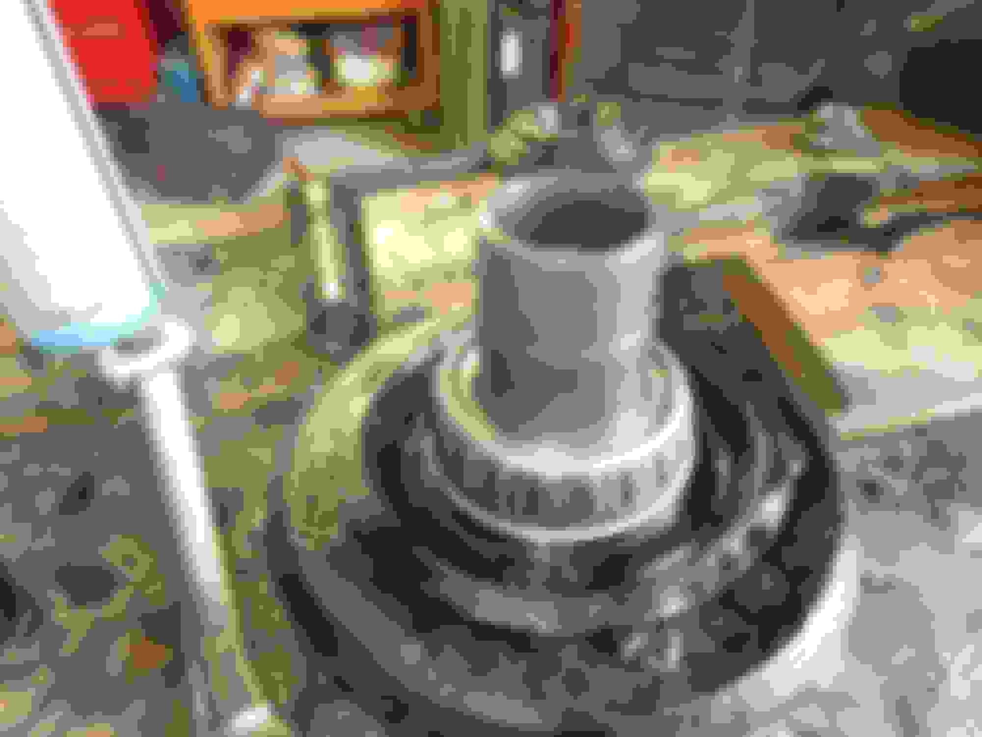
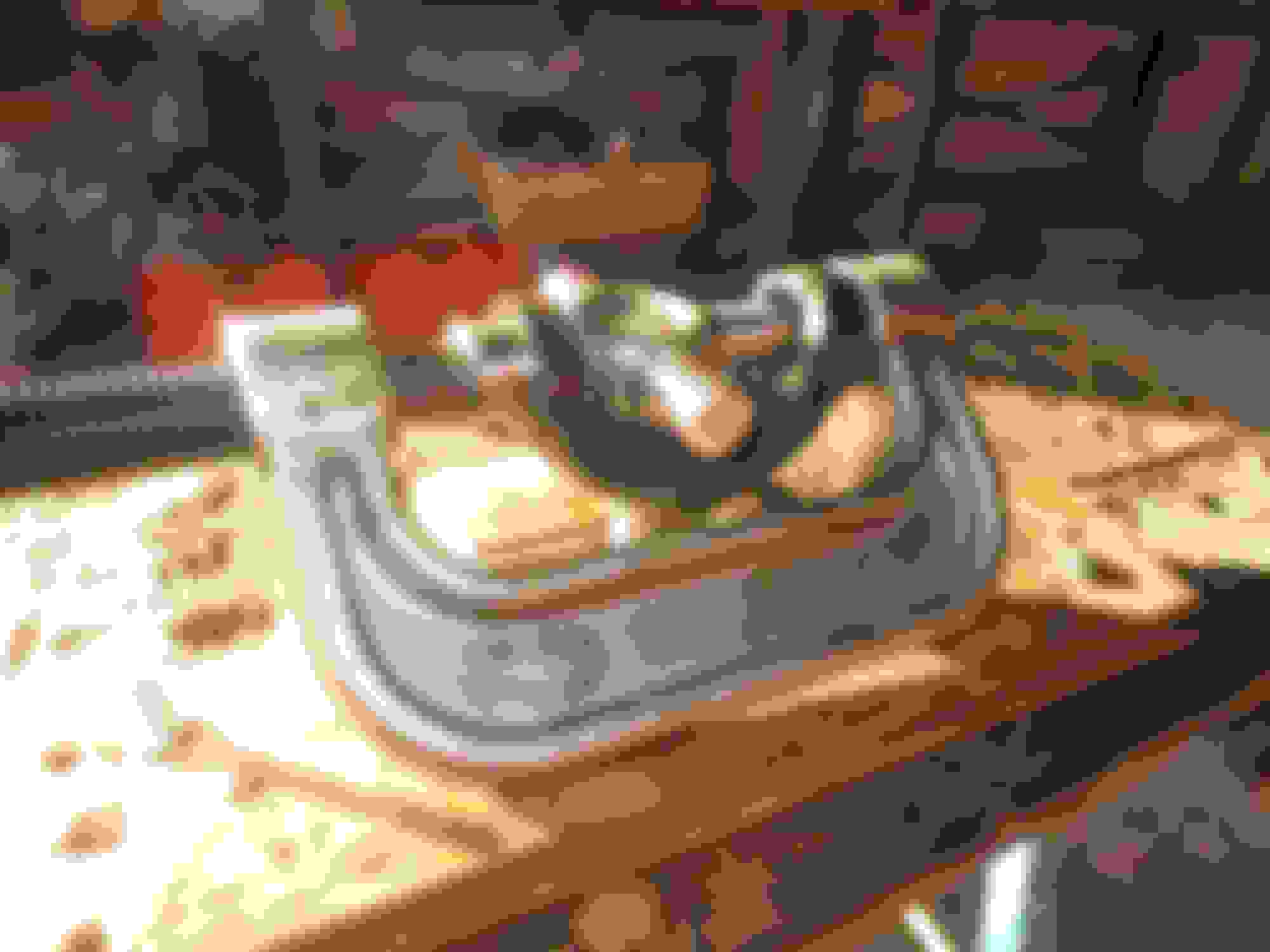
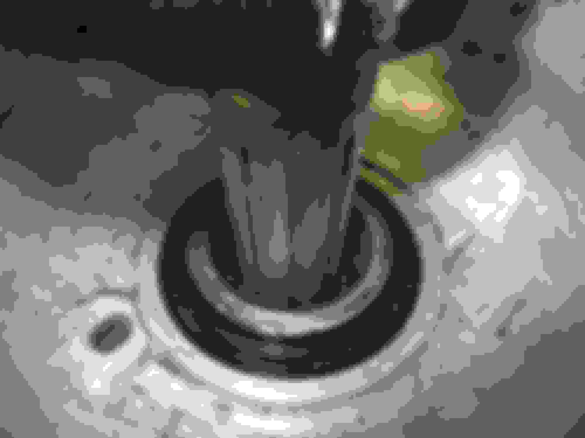
Referring to earlier posts, once the hub and driveshaft has been unbolted for the car, and assuming the lower outer wishbone bearings in the hub carrier are not also going to be renewed, it is important to keep the bearings etc in place. Grant advised me to re-insert the outer wishbone fulcrum pin back into the hub carrier after it had been removed from the car, and to use a length of old radiator hose as a "spacer" in order to keep the bearings under some pressure and thus all safely in place. If any of the shims and spacers involved in setting this fulcrum properly drop out, you will wonder why your lovely rebuilt axle tracks all over the place! Here is a pic of the Grant Francis tip, and it works a treat:
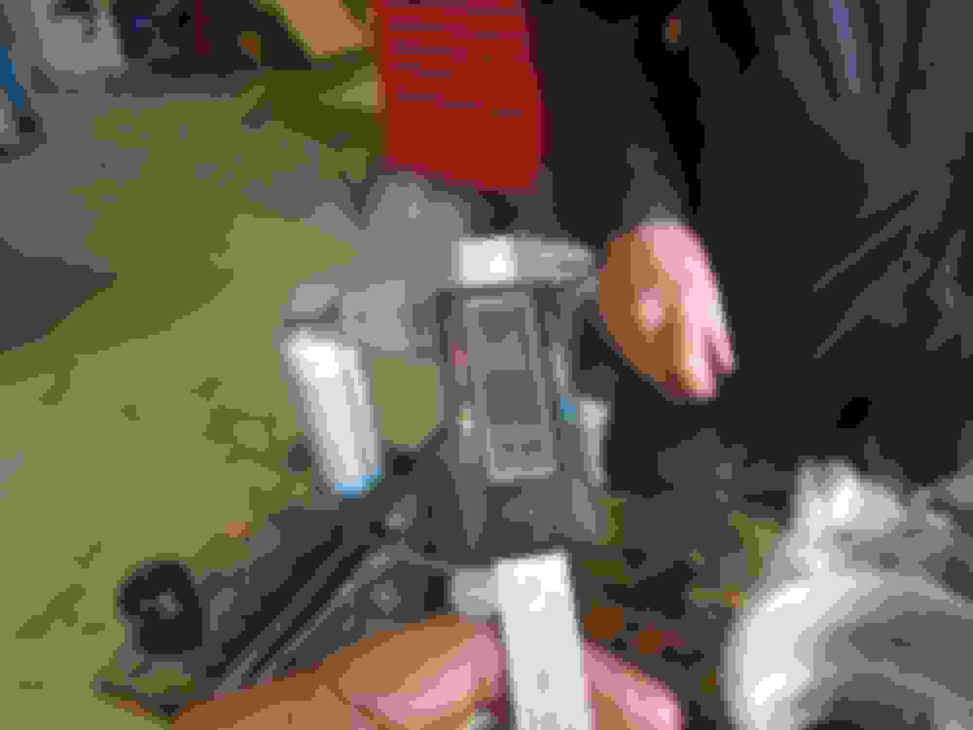
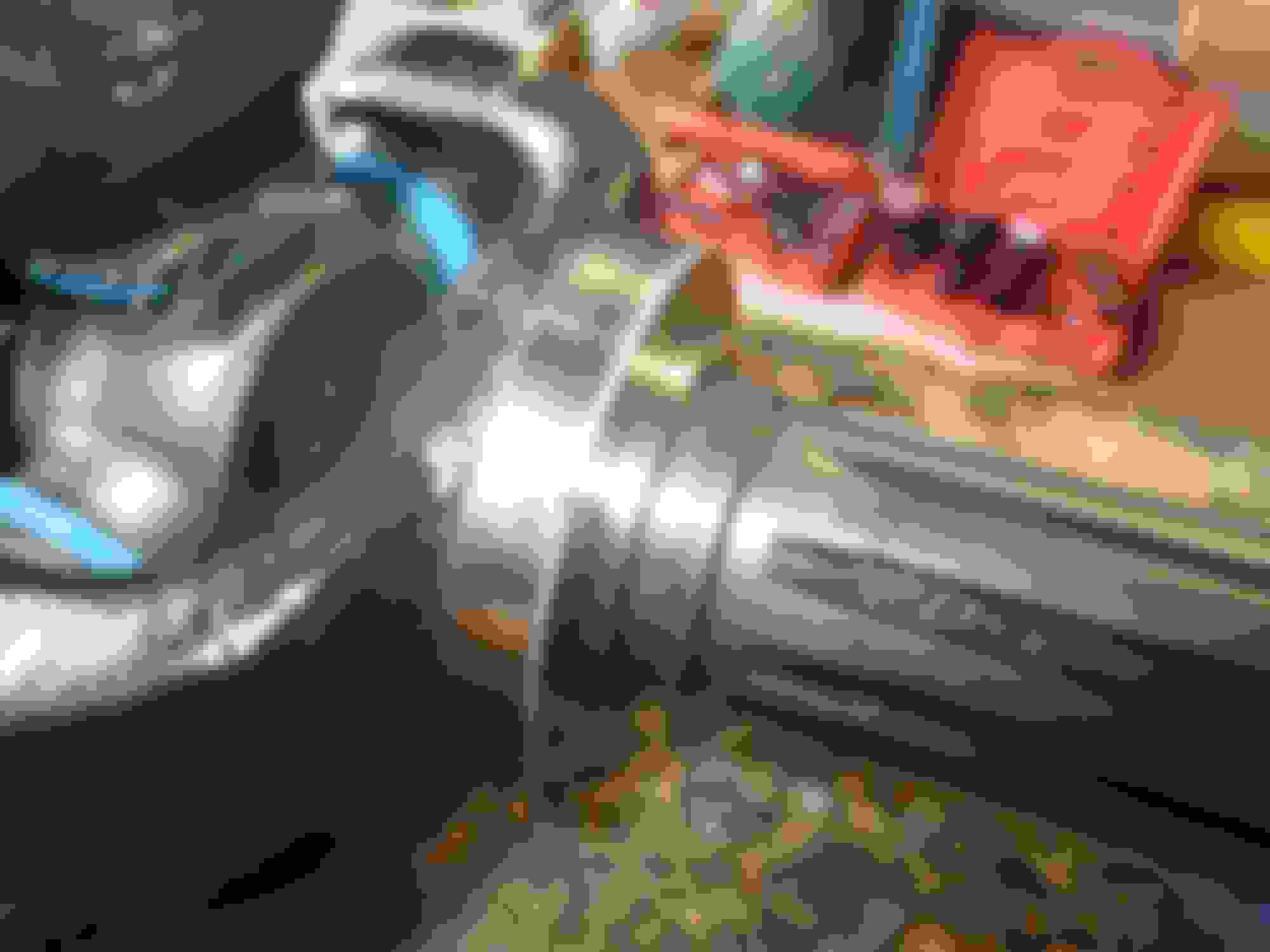
The old UJs have to be removed from the driveshaft and the first thing is to remove the circlips holding the caps into the yokes. I broke three circlip pliers trying to remove the old circlips before I twigged that I should use a screwdriver to get an end bent out and then grip the end with some heavy pliers and wrestle out the circlip that way. This done, I used this cheap but very heavy duty tool to push out the UJ bearing caps:
Actually holding the driveshaft and tool securely and in a good working position took me a while to think out, as they are both extremely heavy. In the end I reinforced the deck of my folding "Black and Decker workmate"- type bench, and that worked really well. The driveshaft was held vertically in it, and the tool's weight could be principally taken by the deck, as shown here:
Anyone not familiar with this bench can read about it here: https://www.blackanddecker.co.uk/en-...orkbench/wm825
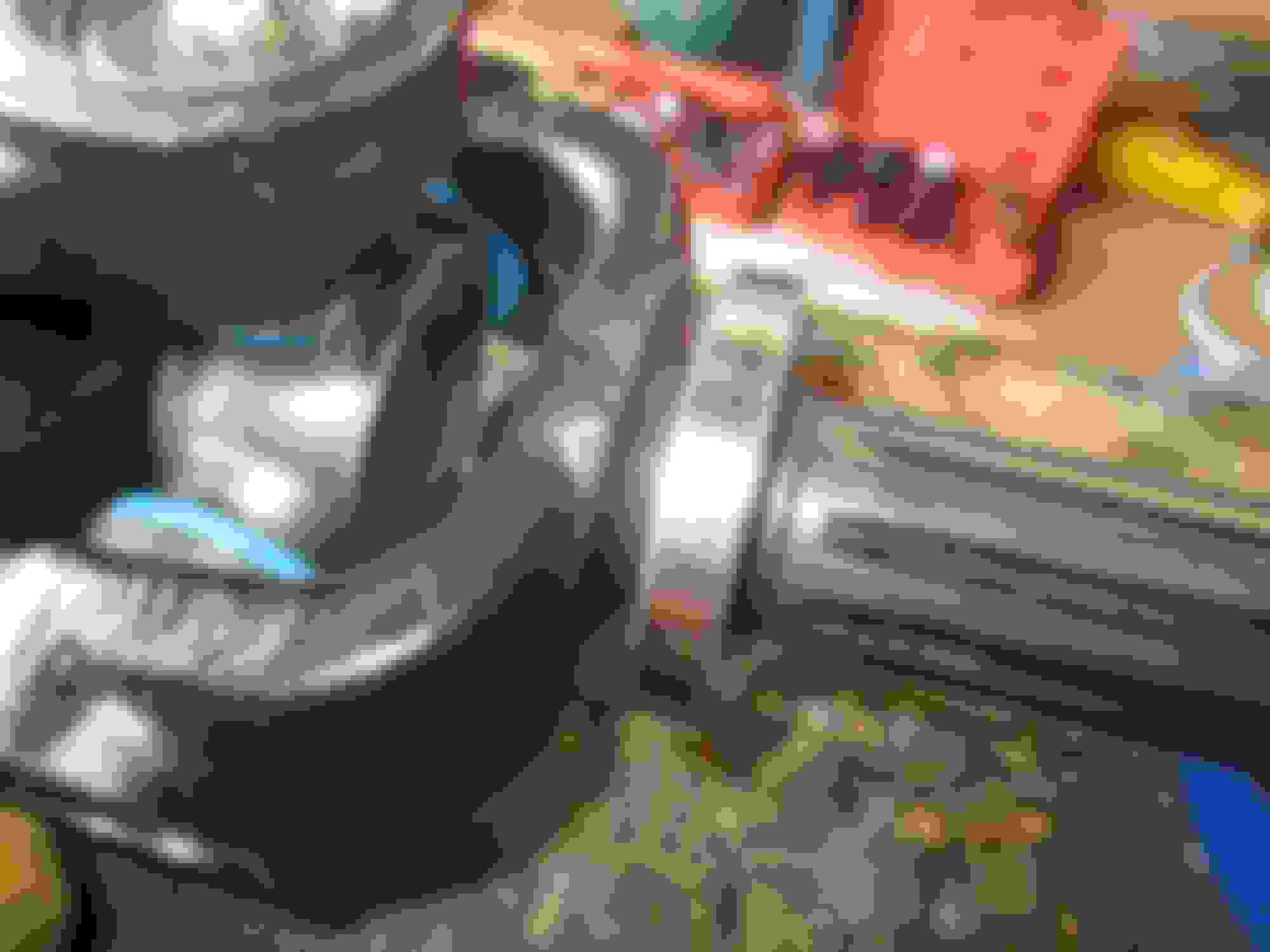
Keeping the tool centralised is a struggle and two people are far better than one for this job. Anyway, once done, the driveshafts will need a clean up and the yokes and their machined holes from which the old UJs have been removed, may well need a careful dressing with a tiny fine file, and/or with some fine emery paper, to ensure there are no rough patches, burred edges, etc etc to ruin the new UJ caps when they are being pushed in. Anyway, assuming all ready to be refitted, here is a pic of the new UJs being fitted:
Note that the cross of the UJ should be held as far as possible fully into the cap as the cap is being pressed in. This helps ensure the tiny needle roller bearings in the cap stay in place, and also allows the helper to keep slightly rotating the cross as the cap is inserted to ensure there is no binding and the cap goes in straight. NOTE also, that the UJs must be greased up with a gun before being inserted, and also CAREFULLY grease with a finger the inside of the caps and the needle rollers, as this also helps stick the rollers in place as the cap is pushed in.
CAUTION: in the end of the cap, on this model of UJ, is a small black, synthetic material, pad with a hole in it's centre to allow grease to get past it and down to the needle rollers. This pad MUST be fitted, and when the caps are removed it usually seemed to stay on the end of the cross. In the immediately above photo, it would stay on the end of the cross where the grease can be seen coming out. It is very easy to lose one of these if you do not immediately remove it from the end of the cross (assuming it stayed there when you pulled the cap off). So if it is there, immediately remove it and press it back into the inside end of the cap.
Once all inserted the circlips can be fitted. Note again: the circlips are a tight fit against the caps. The UJs I strongly recommend (DANA-Spicer units from Rockauto, see earlier posts) come with different depth circlips, and the thinnest ones (149 thou as far as I measured them) are only JUST thin enough.
What i did, again as advised by Grant, was the insert one cap, insert that cap's circlip, then insert the other cap and once that was fully in (and you can feel as you wind the tool the thing get to a STOP against the other cap and its circlip) try the final circlip. It might go in OK, or you might have to give the cap a good tap with a punch, or even another hard squeeze with the tool, to get the last circlip properly in. The importance of cleaning up the circlip grooves in the driveshaft yokes cannot be emphasised too much! Here is a pic:
You will see the grease nipple on this model of UJ is on the end of one of the bearing caps. The nipple is mounted after the cap has been pushed in (obviously!) and on the inner UJ that is fine as far as access for subsequent greasing it concerned. For the UUJ in the hub, however, the nipple is inaccessible once the driveshaft is on the car. If I knew then what I know now, I would for the OUTER UJ in the hub, have bought this "greased for life" version of the same UJ: https://www.rockauto.com/en/moreinfo...78726&jsn=2183
As it is, I have ordered up some 90 degree nipples and will whip out the driveshaft from the hub (easy to do now as it is all anti-seized) and see if they fit OK; but the clearance inside the hub between the UK and the hub carrier is pretty small, so they may not. If the do not clear the carrier, then maybe I will drill an access hole, or do something anyway!
Here is a pic of the finished driveshaft ready to go into the hub, with my shy mate Michel who refused to have his face in shot!:
Note also that the splines, both in the hub itself, and on the driveshafts ned to be 100% clean and rust free. In both cases, after a good clean in solvent, I left them in a bath of a 70% solution of phosphoric acid for about 6 hours. After that all they needed was a wipe with a cloth and they were like new. The splines slipped into each other perfectly after a spray of WD40 after this work, and before fitting finally they were coated with nickel anti seize - an absolute MUST.
Grease all the UJs again with a gun before fitting the driveshafts to the hub.
There are TWO special items to go onto the driveshaft splines before the driveshaft is inserted into the hub:
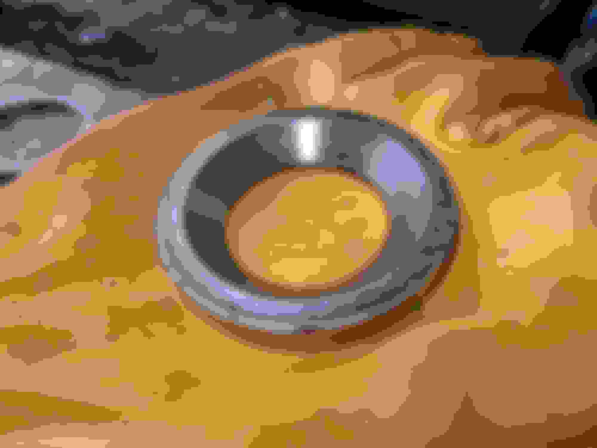
1) the special stainless thick thingy that provides the track for the grease seal to run against, concave side inwards, flat side outwards, pic here:
2) the spacer (see my last post explaining this item):
Now the lot can be fitted into the hub. NOTE in this pic the inner grease seal has been fitted to the hub carrier, and it is easy to forget to do so. The grease seal is the black oil-seal-like ring round the aluminium outer of the hole the driveshaft is being fitted into. The nickelslip anti-seize is on the splines, and the second photo shows the other end of the driveshaft appearing out of the other end of the hub:
All that remains now is to fit the large thick washer that goes under the castellated nut, fit the nut and tighten it to 140 ft llbs, and fit the split pin!
And the hub and driveshaft are ready to bolt onto the car.
When attaching the driveshaft to the diff flange, new metlocs should be used as once undone they do not lock properly. Also (again thanks Grant) put some anti-seize on the diff flange studs as it will aid future undoing - metlocs can be sods to remove otherwise!
Job done!
Last edited by Greg in France; 01-01-2020 at 05:25 AM.
Your rebuild of all the U joints, and shaft's will most surely fix the vibration. Excellent work as always. I do have a question though. Do they make any tougher/ larger, more robust axle shafts, or U joints, for the XJS. As I'm sure 650 hp, and similar torque, will tax these parts to their limits, if not beyond. I've read a lot of the articles of the Racing XJS' and saw no mention of more robust parts, or any kind of torque ratings for the standard parts??? Any knowledge would be greatly appreciated. Thanks for sharing and showing what all is involved with rebuilding the axle shafts etc.

 11-26-2019, 06:02 PM