When you click on links to various merchants on this site and make a purchase, this can result in this site earning a commission. Affiliate programs and affiliations include, but are not limited to, the eBay Partner Network.
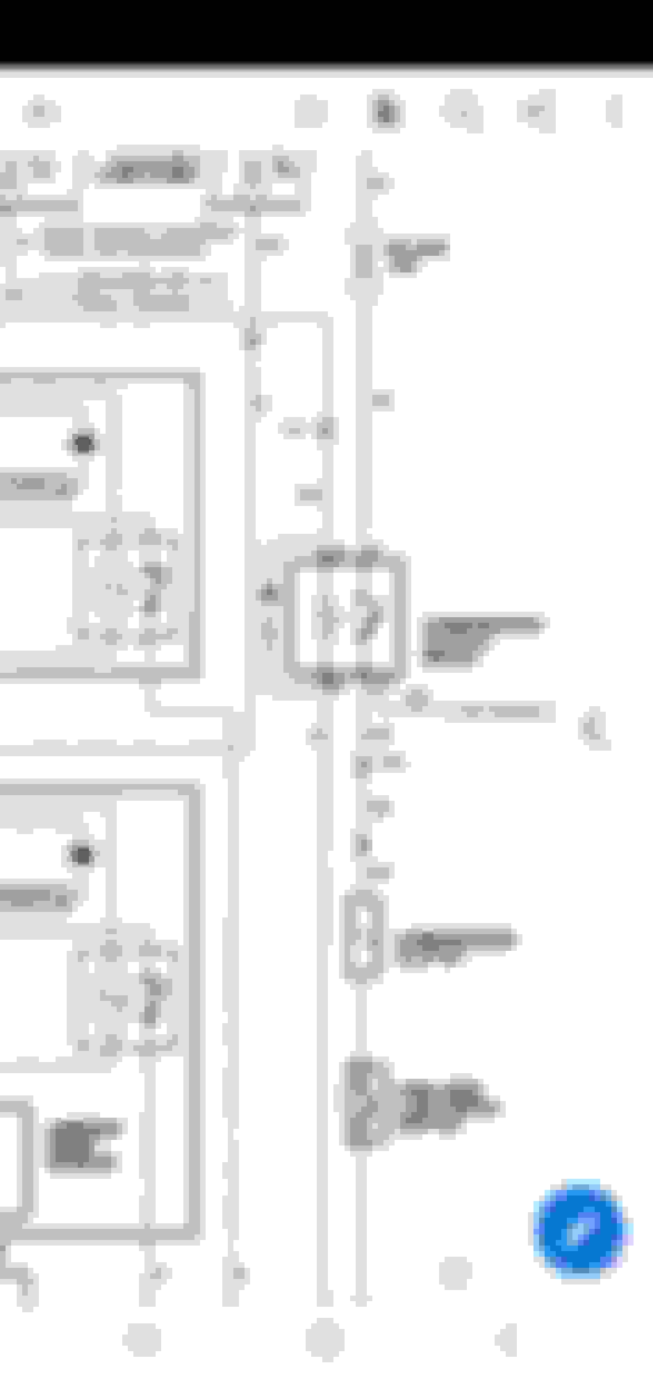
Attached the home made diagram, (ask me if it is not clear) also three photos:
Heavy duty fuse box powering the fan high current relay circuits from the firewall post;
Light duty fuse box handling the switching relay triggers and warning lights etc;
Pic of radiator showing the two heavy duty relays, A = automatic (the relay triggered by the thermo switch) S = Switch (the relay triggered by the cabin switch).
In the diagram the colours refer to the loom colours I used for these circuits. Main fan relays, one for the temp switch (S), one for the cabin switch (A). The OEM ignition-on temp switch live feed still goes to the temp switch in the inlet, but the other side of the switch goes to the main fan relay. Light duty fuses for the warning lights, trigger circuits as shown in the diagram heavy current fuses for the power circuits to the relays. The cabin-switched relay gets its trigger circuit powered from the coil 12v feed, as shown in the diagram, which goes to the relays via this fuse box.
I also attach the spec sheet for the SPAL I have fitted. This is a fantastic fan, it will hold a sheet of paper on the front of the condenser when running. It is crucial to mount the fans as close to the radiator as reasonably possible. Mine are about 3/4 inch away.
So I'm just drawing this out for the main fan only.
This is what i have but im confused about #6 and the extra connect on the water pump housing switch.
Numbers are based on your diagram and also no backup switch in cabin to keep it simple for now.
my hoses from SNG in the UK showed up today, So now just waiting for that 16 inch fan to show up so I can get a shroud made.
info for my about the AAR screw - The farther this bolt is screwed in, the more the bolt obstructs the passage, and the slower the engine idles. I think mine is having issues. been a year since i had it running so I will need to see. temp is about 15C in the mornings and 20sC in the day so it shouldnt idle high once I get it running for more then a minute or so
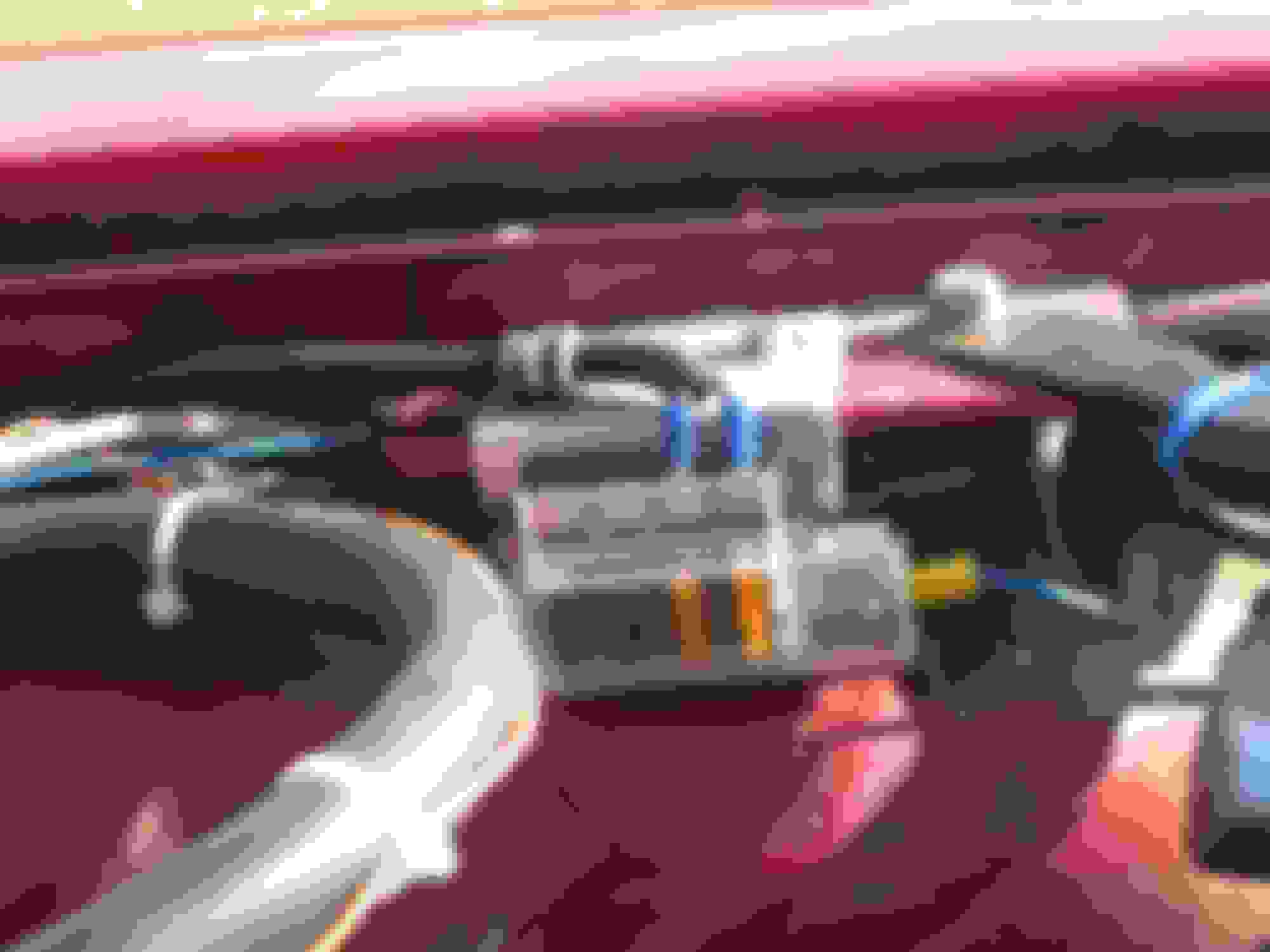
Made some more connections of little vac lines etc.
So the big hose in the middle goes to the LHS TB underneath. Where it came from.
The other end went to a hose that lead to the air pump (now deleted) the 2 wires go to the cruise control harness
Should I just leave it like it is venting to the atmosphere or I could run a hose to the lhs air box as there's extra holes there now lol.
The next 2 items in the pics below are 2 items that wont be connected to anything anymore as they were emissions related I think. Should I cap them. The purple one is at the rear of the lhs water pipe housing. The other one is behind the thermostat sensor for the efi on rhs.
Thoughts on capping the broken holes in the 2 devices?
the one with the bosch connector on the lhs makes sense to me. This is the one that goes to the efi apparently.
The 2nd on on the rhs (1 wire) is for the gauge I have read but it actually goes to the connection at the front of the a/c unit.
When my xjs was running the gauge actually worked.
Is it suppose to go to through the a/c compressor harness which is a 2 wire plug that connects to the top lhs of it?
Or am I missing a wire somewhere.
Just trying try figure it out.
I think that's right. My gauge wire runs over to the AC compressor then disappears. I haven't put too much effort into tracing it as the gauge works. I will soon be putting some effort into it as the AC doesn't work.
I think that's right. My gauge wire runs over to the AC compressor then disappears. I haven't put too much effort into tracing it as the gauge works. I will soon be putting some effort into it as the AC doesn't work.
Ya I finally traced it last night. It goes into the small wiring loom right under the compressor. Like a Y.
Rescue (I have been away, so apologies for the late replt).
6 goes to the cabin warning light, via a 3 amp fuse in the small fuse box. If you are not having a cabin light, no need for it.
The wire from the water pump inlet thermostat you also have a question mark by. There are two OEM wires that go to this switch: one carries the 12v live always, and one carries the current AFTER the switch has closed to the OEM relay.
If you are basically using Grant's system, you disconnect this second wire, the one that is on the downstream side of the switch, and you run a new one from that side of the switch to the relay that triggers your new main fan.
The smaller fan you are installing to replace the OEM electric fan, is wired to always come on with the aircon compressor, and the OEM wire you have disconnected from the downstream side of the thermostatic switch is wired to the aircon compressor feed.
No worries. Hopefully somewhere nice!
So if I connect the battery I should be able to test to see which one is the 12v live always. I suspect it's the blue/white (UW according to ROM) wire. Other one is solid white.
In that wiring loom there is a 3rd wire (2 for the thermostatic switch in the water pump) and one wire that was connected to power the OEM aux fan. Couldn't I use that feed to go to the relay for the new 12" fan to tigger it to come on?
I also tested the temp sender on the rhs and the omhs read correct according to the ROM.
Assuming you are using Grant's fan control scheme:
So if I connect the battery I should be able to test to see which one is the 12v live always. I suspect it's the blue/white (UW according to ROM) wire. Other one is solid white. Ignition on, one of the two wires going to the thermostatic switch will carry 12v. This you leave, and run a new wire from the other side of the switch to your new relay. Thus when the switch closes, your main fan will be triggered.
In that wiring loom there is a 3rd wire (2 for the thermostatic switch in the water pump) and one wire that was connected to power the OEM aux fan. Couldn't I use that feed to go to the relay for the new 12" fan to trigger it to come on? Please explain what you mean, I am not sure if understand which loom you are referring to.But in principle, the OEM power wiring to the replacement for the OEM electric fan, is not affected by your changes to the thermostatic switch wiring. In Grant's scheme, the feed to the aircon compressor triggers the OEM fan power circuit, instead of the feed via the thermostatic switch. You do NOT need a new relay for the new fan that is replacing the OEM electric fan, all you need to do is to trigger the OEM power circuit using the aircon feed instead of the feed via the thermostatic switch.
When you wire up the new fan that replaces the OEM electric fan, you just need to connect the OEM fan motor wiring to the new fan's motor wiring. The only chnage is to how that fan's OEM relay is triggered, and it is the aircon feed that you use by taking a branch off it and connecting that to the wire you removed from the downstream side of the thermostatic switch.
The earth wire from both the OEM electric and therefore from your new one, goes to earth on the rearmost fixing bolt of the radiator top panel, LHS, and you will see a load of earths there from the OEM loom. One of which will be from the OEM electric fan.
Last edited by Greg in France; 06-17-2022 at 07:10 AM.
The 3 wire loom is the 2 wires for the switch and 3rd wire for oem fan power one.
This actually goes into the main loom that's one the lhs fender near the front. Which is for the loom that goes across the front rad support /relays so on.
Clear as mud eh.
I'll get a pic after work but what you are saying makes sense.
The only chnage is to how that fan's OEM relay is triggered, and it is the aircon feed that you use by taking a branch off it and connecting that to the wire you removed from the downstream side of the thermostatic switch.
Ok got it. Had to read the response a few times to understand it.
So I would run a wire from clutch relay #30 wire to WU wire (which is the wire i will remove from the thermo switch)
So when the clutch compressor relay is activated it will send power to the wu wire which will activate the fan relay and thus turning on the aux fan via OEM wire.
Sound right?
Also does it matter what prong on the thermostatic switch gets the 12v? I don't recall which wire (w vs wu) came from which prong.

 06-08-2022, 10:06 AM