When you click on links to various merchants on this site and make a purchase, this can result in this site earning a commission. Affiliate programs and affiliations include, but are not limited to, the eBay Partner Network.
Guys
Many forum members with V12 HE engines, on this XJS forum and on the Series III one, have Lucas ignition cars. It is a very reliable system; but as with any non-digital ignition, it does need servicing from time to time, and it has two particular semi-failure modes that occasional servicing prevent. Ancient drivers like me rather like such old systems, as they have many stages between working perfectly and actually stopping the engine dead. Modern systems have two stages only: working perfectly and failing completely!
The two semi-failure modes are
The central column on which the rotor sits is sprung, such that you can turn the rotor about 15 degrees against the spring and it will snap back when you let go. If the column is not given a few drops of synthetic engine oil once a year, it can jam so the rotor cannot move as designed. This does not stop the engine, but it reduces power and efficiency.
The other mode is that the vacuum capsule fails so that there is no vacuum advance applied to the ignition. Once again, this does not stop the engine, but it does noticeably increase fuel consumption. Down from say 18/19 Imperial MPG to 14/15. It does not seem to noticeably reduce power, so fuel mileage dropping is the main symptom. Sadly the quality of vacuum capsules available to buy today (as no car maker uses them anymore) is often very poor and they can fail after a few years or sooner. The test to confirm failure is to unplug the rubber vac tube leading from the unit to the various vacuum controlling gizmos on and around A bank manifold, and suck. If air flows though when you suck the vac pipe the rubber diaphragm in the unit has failed and it has to be replaced.
Failure mode 2 has just happened to me, though it took me a couple of months to twig the problem. On advice given by another member on a thread I cannot recall, the poster recommended vacuum capsules made in the USA by an outfit called British Vacuum Unit, so I ordered up one of theirs, part JLM 519, in the hope it will be robust. I spoke on the blower to the guy who runs it Rob Medynski 01 603-731-1788 and he was very helpful. His website is britishvacuumunit.com and email is bvu@britishvacuumunit.com and he stocks vac units for just about every make of British Classic Cars. I have no affiliations with the business and received no discount!
Anyway, after a few days the new unit made it through customs and turned up, so I have just fitted it. As far as I know there is no thread that properly illustrates the process of getting the distributor apart, so I thought I would document what I did.
The capstan and throttle tower
Although it is just possible to do it without doing so, removing the capstan and the tower it sits on greatly eases the job. The capstan is removed by pulling the throttle rods off it, removing the accelerator cable inner from its slot in the capstan, and undoing the four 7/16ths fixing nuts that attach it to the tower. Pull it carefully off and place the long spacers and nuts in a container for safe keeping. The capstan togther with the TPS underneath it, and the accelerator cable can then be moved aside without having to unplug anything else. Blue rings round the capstan and the accelerator cable placed out of the way. The TPS under the capstan is still plugged into the loom.
The plate that holds the coil is under the capstan and it too can be lifted clear out of the way once the connectors on the + and - terminals are undone and MARKED!
Now you can get at the tower fixings. The tower is bolted to the V bottom by four 7/16ths bolts, one at each corner. The rear two are sods to get at, requiring bent spanners and all sorts of grief, and the front A bank side one is usually hidden under the vac capsule! I was advised by Grant Francis (turn to Southern Cross and bow at the mention of his name) to drill the tower, once off, to allow easier removal in the future. Grant also advised slotting the rear two holes so that te bolts just need to be loosened not removed, which greatly eases things too. Pics here:
I also replaced the front A bank side hex headed bolt with an Allen Keyed bolt that can be undone by a long key, thus removing the problem of the bolt head being masked by the vac capsule.
Taking the distributor apart
Remove the HT leads from the distributor and make a map of where each went on the cap such as this:
Remove the three captive screws that hold the dizzy cap down to the metal unit
Pull off the cap and carefully remove the ventilation pipes from it
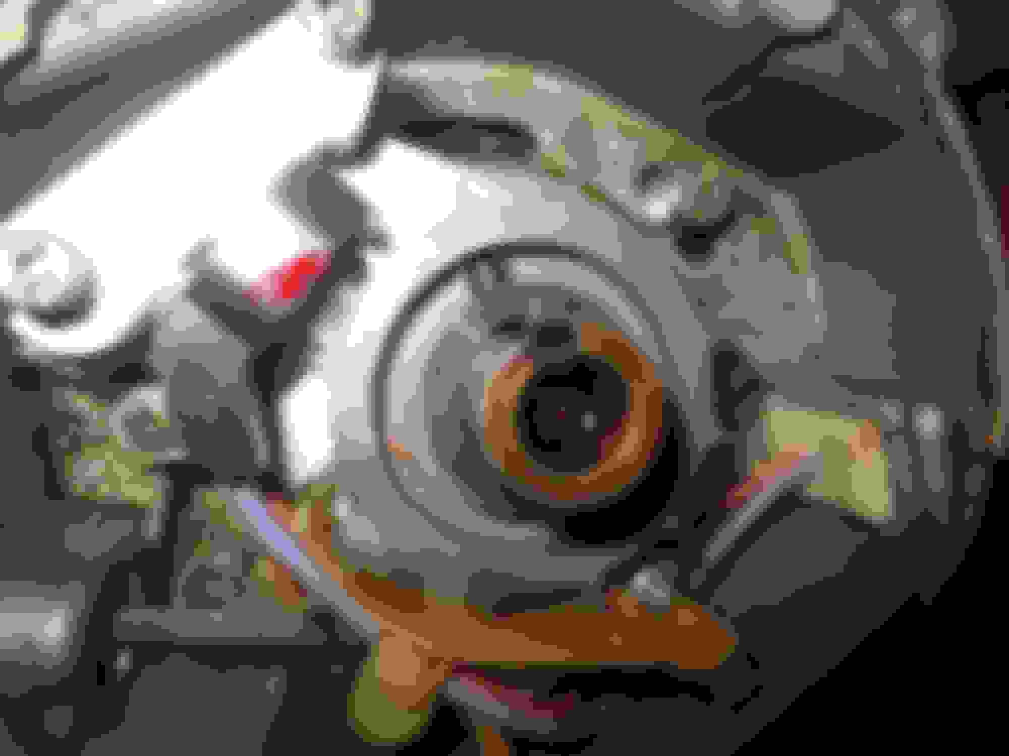
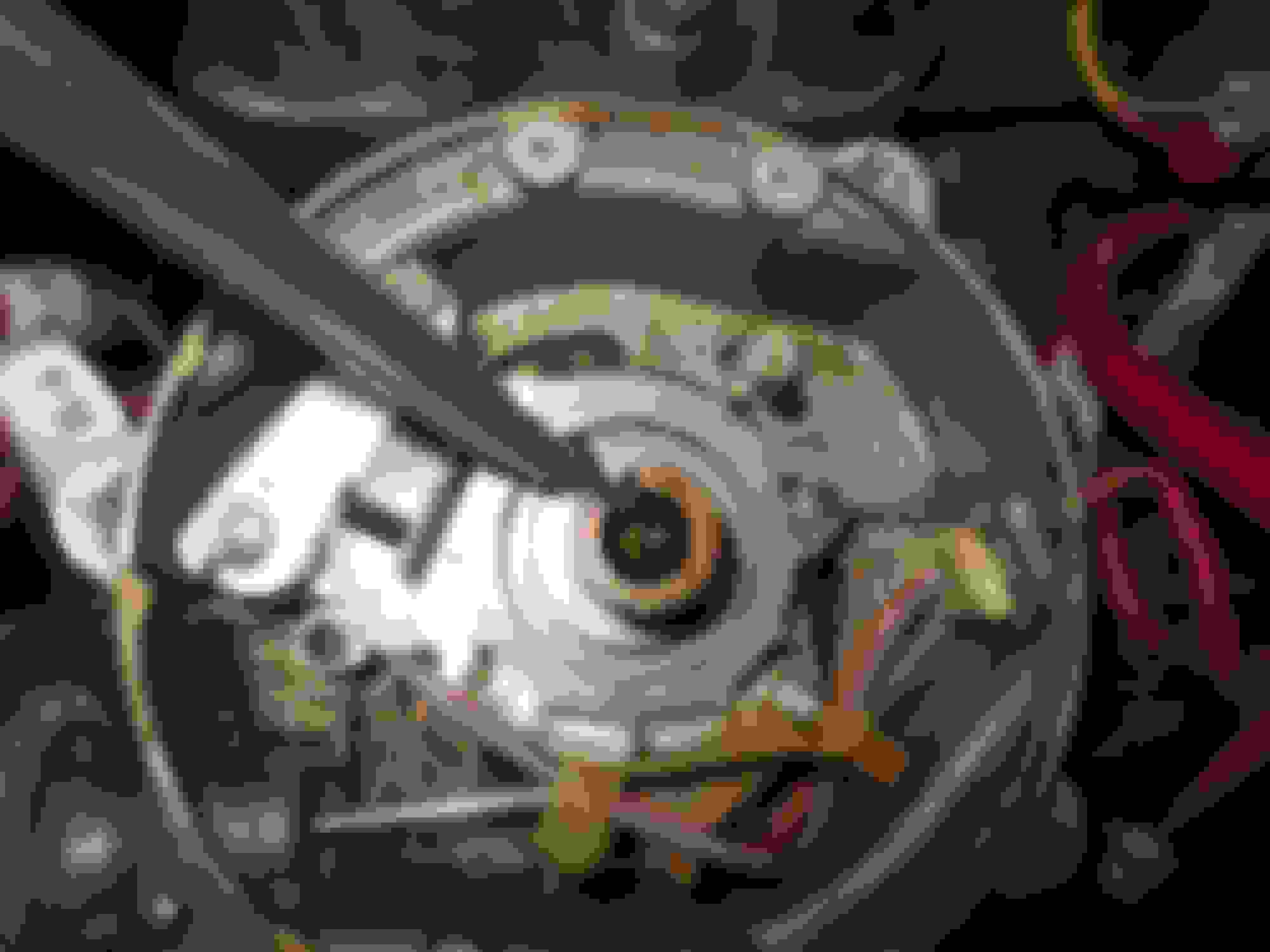
You can now see the rotor. With a hand each end of it, rock it gently up and down (up one end while pushing down the other) until it eases off the column. DO NOT pull the rotor straight up or you will break the dizzy. The distributor now looks like this, the rotor having been removed from the central column:
The flash shield (if there) is fixed by four small screws, undo them and lift off the flash shield. NOTE the drops of oil in the column 'hole' under the rotor, this is where you add oil to prevent the advance sprung rotor jamming (see mode 1 at the start of this post).
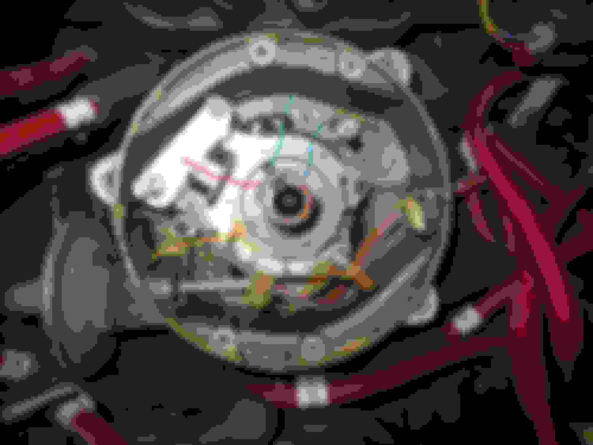
You now see this: Red line points to the circlip. Blue line points to the wavy washer. Green line points to the U shaped sprung clip. Yellow line points to the 12 pointed starwheel.
The starwheel has 12 points because as each point goes past the magnet (the red line above runs through the fixed magnet) it creates a change in the pickup voltage which is the signal to the Lucas amp to fire the coils. The starwheel is held in place by a) the circlip, b) the wavy washer and c) the U shaped sprung clip. Shown here in closeup: This shows the three starwheel fixings in closeup. The red mark shows the magnetic pickup that activates the coil when the points of the starwheel rotate past it. This process is called (I am told) the Hall Effect, named after the guy who discovered it.
Remove the circlip first using expanding circlip pliers, these parts must NOT be lost down the V ! Then you can pull off the wavy washer, both shown here removed and placed sfaely in the container:
Next the U shaped clip and starwheel must be removed, this clip locks the starwheel to the column. Removal must be done with EXTREME care as if lost I have no idea where to get anothe one! Close up before removbal of the clip here: You can see the clip is locking the starwheel to the column
Use snipe-nosed pliers to grip it each side and gently pull it upwards, keeping a firm tension on the clip with the pliers. As soon as it is off into the container for safekeeping. U shaped clip removed The starwheel can now be carefully pulled up and off the comumn. It is BRITTLE so use FINGERS ONLY and place in a plastic container
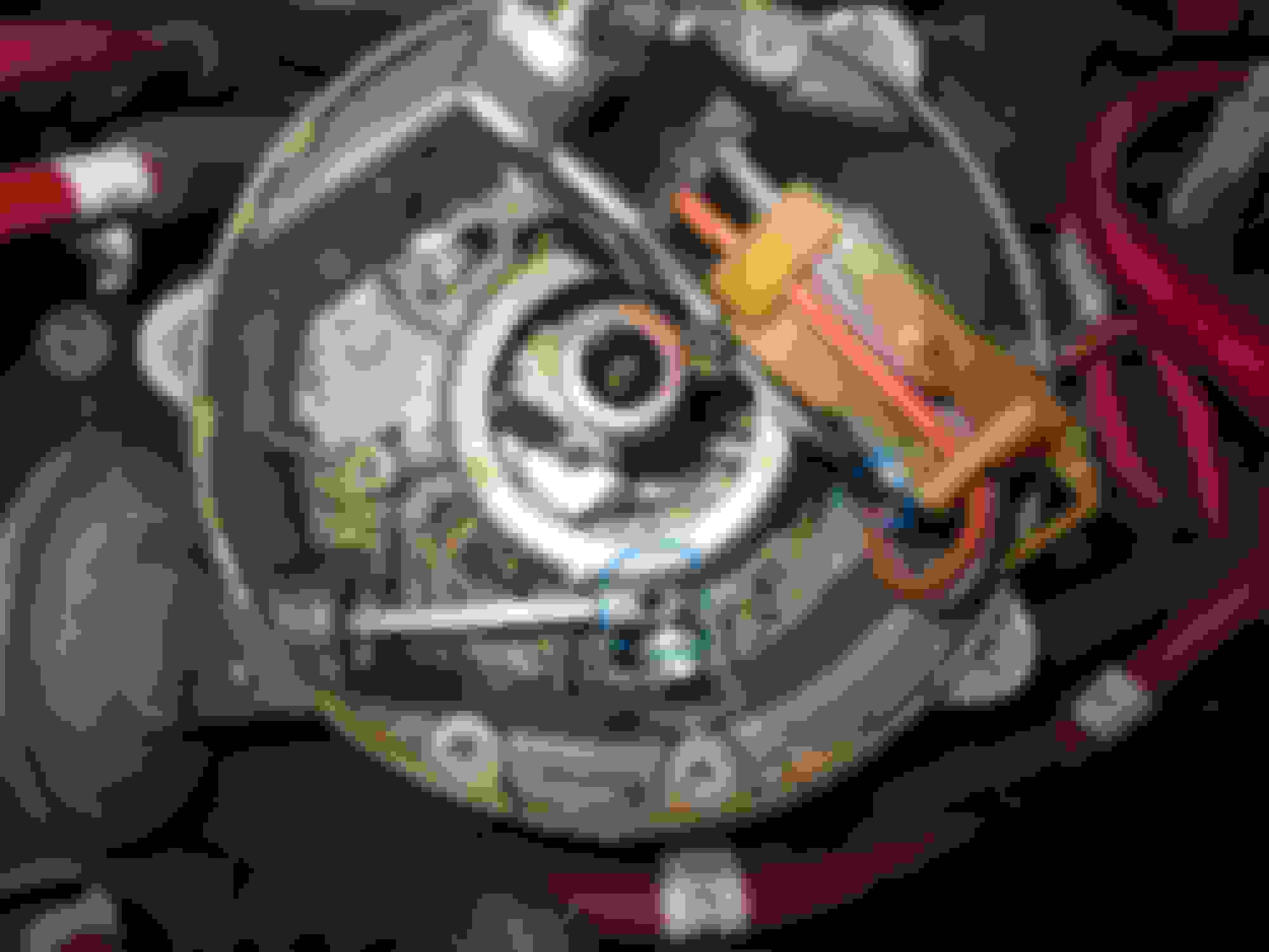
The distributor now looks like this: Blue line shows the vac capsule. Red rings show the two pozi screws that hold the pickup assambly to the dizzy chassis. The end of the arm of the vac unit (shown with the star marks in blue at the R/H end) goes onto a downward-facing peg under the assembly at the point marked by the blue star marks.
The two pozi screws marked in red above now have to be undone. These must be undone CAREFULLY so they are not dropped. Loosen them part way and then unscrew and remove by hand. Loosen screws with a driver and then undo and remove by hand. Do NOT lose these! The entire pickup unit can now be lifted to one side to show the peg that fits into the vac capsule arm: Peg on the underside of the pickup unit and hole in the arm for the peg ringed in blue.
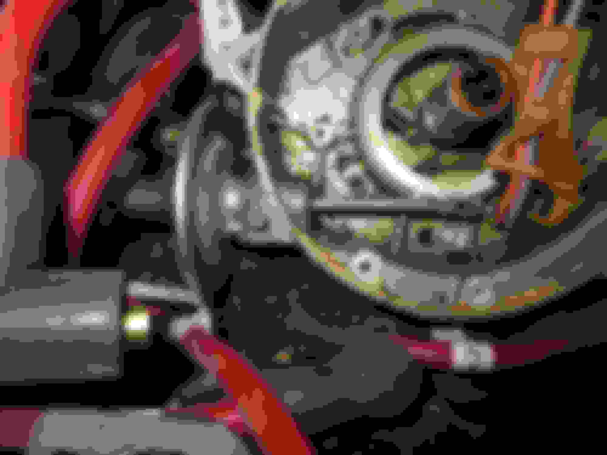
Now you can remove the failed vacuum unit. It is held into the dizzy chassis (OEM) by a TINY rollpin. You need a 2mm punch to remove it. Thanks to my friend Martin at Classic Engineering near London, some years ago I replaced the rollpin with a small stainless self tapper. This makes removal of a failed unit far easier: Drive out the fixing pin (or undo the self-tapper) and the old vac unit can be pulled out of the dizzy chassis.
Now the new unit can be put in place and the pickup unit replaced, being careful to ensure the peg is engaged in the vac unit arm. Closeup of new vac unit in place and fixing screw (or rollpin) ready to be tightened
Close up of the pickup underside showing the peg that MUST be engaged pointing downwards through the hole in the end of the arm.
Now replace the pickup unit and replace the two fixing screws (ringed in red in photo) shown in stage 10 above. Note that the L/H screw ringed in the photo in stage 10 above goes into through an articulated arm, which must be placed over the threaded hole before the screw is inserted. The arm of the pickup marked in red is articulated and must be placed in position before the fixing screw is replaced
These are hard to get started with older fingers, so placing them in a bit of rubber pipe can help ensure they do not go AWOL:
Now replace the starwheel, align the slot in the starwheel with the slot in the column and using snipe nose pliers again, raplace the U shaped clip, get it started in position and then press it home with a screwdriver: U clip in pliers ready to be replaced Once put in place and engaged enough with the pliers, press fully home with a screwdriver pushing into the U to lock the starwheel to the column
Now replace the wavy wasker and the circlip on top of it. Push the circlip downwards with a screwdriver all round to ensure it clicks home fully: pushing the circlip fully home so it clicks into the groove in the column
Replace the flash shield, trying not to lose all four fixing screws (I lost two somewhere in the V):
And NOT forgetting to replace the rotor, fit the dizzy cap, screw its three fixing screws down. Then attach the vac tube to the new unit. I use a right angled fitting to help lead it easily up to the A bank inlet manifold spigot:
Now you can refit the HT leads and ventilation tubes: This is the HT lead map I made when I first bravely replaced the plugs back in 1998! Something like this saves worry! Original HT map kept and used for sentimental reasons.
The final photos:
All that is left to do is to replace the throttle tower, refit the coil and capstan, connect the coil leads, hook up the accelerator cable and the HT lead from the coil to the distributor cap centre terminal, and the job is done!
I have attached a pdf if anyone wants to print this for reference.
Last edited by Greg in France; 03-30-2024 at 02:49 AM.
I would want to clean and lubricate the baseplate too to make sure that it rotates smoothly and freely. I once bought a new Jaguar vac capsule that came with the baseplate. I tested it and I couldn't move the baseplate at all, so reused my original after cleaning and swapping the new vac capsule over.
Another candidate for the mileage dropping is the dump valve has failed, and that dumps the vacuum before it reaches the advance capsule. So always test with a line from the manifold to see if that restores the fuel economy or not. You could also use a hand vacuum pump to see if the capsule holds vacuum and actually advances the baseplate.
Wow, Greg! What an amazing and useful post!! I think you may have outdone yourself here!! As I will be doing plugs, wires, cap, rotor, etc. in the near future, this post is extremely timely! I just love step-by-step instructions, with photos and tips along the way, simply marvelous! Thank you so much!!!!!

 03-29-2024, 08:47 AM