When you click on links to various merchants on this site and make a purchase, this can result in this site earning a commission. Affiliate programs and affiliations include, but are not limited to, the eBay Partner Network.
We need of some expertise/suggestions to help start a 1978 Jaguar XJS V12.
Two Jaguar amateurs (Body/Paint Man and 57 Chevy Guy) learning about a Jaguar.
Using XJ-S Repair Operation Manual and Parts Catalogue-Jan 1977
Trying to maintain original engine equipmant.
The car has not been started for over 15 years. It has very low mileage (less than 30K).
I will try to explain the progress we have made, but need a suggestion of what to look at next.
Steps taken so far.
1. New Battery
2. Cleaned gas tank and lines.
3. Tested spray at cold start injectors OK.
4. Turn Key on, Dash lights and main relay powers up. OK
5. Fuel Pump runs, pressurizes fuel rail. OK
6. Fuel Pump turns off.
7. Key to start position, starter turns over, engine starts.
8. Engine runs great off �cold start� for 2 seconds. (Ambient Temp is 80F)
- Distributor OK.
- Plugs OK.
- 12 volts to injectors OK.
9. Fuel Pump does not restart.
What can we test next?
What signals the ECU to start the fuel pump and injector pulses?
I have been there myself. It runs in 2 seconds because the cold start injectors works.
The rest of the injectors dont start up.
My fault was that I put in a new rotor in the distributor and that was the wrong type. Check if you have the rotor with the magnet in the back end.
The magnet gives pulses to the injector system. The D-jetronic is the only one that works this way and it is hard to find the right rotor.
We need of some expertise/suggestions to help start a 1978 Jaguar XJS V12.
Two Jaguar amateurs (Body/Paint Man and 57 Chevy Guy) learning about a Jaguar.
Using XJ-S Repair Operation Manual and Parts Catalogue-Jan 1977
Trying to maintain original engine equipmant.
The car has not been started for over 15 years. It has very low mileage (less than 30K).
I will try to explain the progress we have made, but need a suggestion of what to look at next.
Steps taken so far.
1. New Battery
2. Cleaned gas tank and lines.
3. Tested spray at cold start injectors OK.
4. Turn Key on, Dash lights and main relay powers up. OK
5. Fuel Pump runs, pressurizes fuel rail. OK
6. Fuel Pump turns off.
7. Key to start position, starter turns over, engine starts.
8. Engine runs great off �cold start� for 2 seconds. (Ambient Temp is 80F)
- Distributor OK.
- Plugs OK.
- 12 volts to injectors OK.
9. Fuel Pump does not restart.
What can we test next?
What signals the ECU to start the fuel pump and injector pulses?
OK, as mentioned the rotor.
My systematic test on these things is:
1) Rotor has a magnet imbedded in the heel, and ensure it IS a magnet still, NOT strong, just a magnet
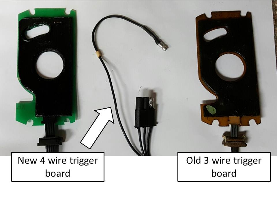
2) The trigger board. YOU will need to tell me which trigger board is in YOUR car. Look at the rear of the distributor, just below the cap edge, and there is a flat loom poking out, does this loom have 3 wires OR 4 wires????? Then I will explain the testing of YOUR board.
3) Ign ON engine OFF, QUIET AREA, open the throttle capstan and LISTEN for about 9 clicks of the Injectors, as you travel from Idle to WOT (Wide Open Throttle).
Lets know your findings and I can continue. These are SIMPLE systems, and there are a few known issues to diagnose before getting too deep.
I reckon you have lost Injector Pulse, and those 3 things above will track it quickly.
Grant,
Thanks for your quick reply.
We will be getting together in the garage early next week to do a more detailed look.
Meantime, we have two answers for you;
2. There are three wires in the ribbon coming off the distributor. I think this means it is an original design.
3. Ignition On/Engine Off and turning the throttle capstan, there are no clicks to be heard at all. Does this
mean the contact signals are not getting back to the ECU?
Early next week, we will remove the distributor cap and check the magnet. Perhaps we can also do
a resistance test of the pickup module or perhaps these is a test we can do using an analog volt meter.
The 3 wire board is the original, and has reed switches imbedded in the mastik.
SIMPLE test:
Cap off, take a magnet (I use a magnet on a stick), and wave this magnet over ONE end of the board, and listen very carefully, and you should hear clicking of the switches. Then do the same at the other end. You will need a VERY quiet area, and listen very carefully. NO need for Ign to be ON. That oriignal 3 wire was a PITA, so if you have one that is clicking well at both ends, the Jaguar Gods are in your favour.
Check the rotor for that magnet. DO NOT go crazy pulling that rotor off the shaft, you WILL damage the internals of the distributor, and/or break that plastic wheel, and basically ruin your day and bank balance. If that rotor is stuck, use a screwdriver and push DOWN on the centre shaft as you pull UP on the rotor, thus equaling the forces of UP and DOWN. Rocking the rotor also helps.
NO clicking with the throttle switch is an issue for sure. #1, reach down and ensure that the throttle switch loom is actually plugged into the throttle switch. They have a habit of falling out and sitting inside that big rubber boot, and you will never see it. Failing that, the throttle switch may be dead, but lets go there later.
Forget the reluctor etc, as you have spark.
Last edited by Grant Francis; 09-19-2019 at 09:29 AM.
The 3 wire board is the original, and has reed switches imbedded in the mastik.
SIMPLE test:
Cap off, take a magnet (I use a magnet on a stick), and wave this magnet over ONE end of the board, and listen very carefully, and you should hear clicking of the switches. Then do the same at the other end. You will need a VERY quiet area, and listen very carefully. NO need for Ign to be ON. That oriignal 3 wire was a PITA, so if you have one that is clicking well at both ends, the Jaguar Gods are in your favour.
Check the rotor for that magnet. DO NOT go crazy pulling that rotor off the shaft, you WILL damage the internals of the distributor, and/or break that plastic wheel, and basically ruin your day and bank balance. If that rotor is stuck, use a screwdriver and push DOWN on the centre shaft as you pull UP on the rotor, thus equaling the forces of UP and DOWN. Rocking the rotor also helps.
NO clicking with the throttle switch is an issue for sure. #1, reach down and ensure that the throttle switch loom is actually plugged into the throttle switch. They have a habit of falling out and sitting inside that big rubber boot, and you will never see it. Failing that, the throttle switch may be dead, but lets go there later.
Forget the reluctor etc, as you have spark.
Added information.
We have removed the distributor cap and pulled the rotor with no problem.
The magnet at the end attaches with noticeable strength to a pair of pliers.
Good magnet.
We will check and clean the connector contacts to at the throttle switch.
On Monday we will and use a small parts pickup magnet and attempt to make
the switches click on both ends of the board.
Regards
Denny
Updates on our status and results of tests Grant suggested.
This car has only 19,000 miles
We retested all of Grant's suggestions. In reverse order.
1. There is no clicking on rotating the throttle capstan. We double checked and all connectors are clean and connected.
2. With distributor cap removed the rotor comes off easily. Looks good and clean.
The magnet is quite strong.
3. With the rotor out, and a very quite environment, we moved a magnet over the trigger unit surface in the circumference of the magnet's arc.
NO clicks at all heard.
Then we moved the magnet to all areas of the trigger unit. NO Clicks at all heard.
Next we used a magnet somewhat stronger than the rotor magnet. NO clicks were heard.
4. To verify the Trigger Unit we refer to, it is directly under the rotor surface. It appears to be an epoxy covered board..
However we cannot make out a location for the switches unless they are buried in the epoxy.
I have pictures I will send in a later update.
5. As a further test we used the Trigger unit Test in the Repair Operations Manual.
With an analog meter (Simpson 250) measuring ohms between the center pin (12) and Pin (21)
and the ignition on we engaged the starter for several turns, but did not observe any resistance
swings. We then repeated the test between pins 12 and 22. No needle movement.
The manual suggests the trigger unit must be replaced.
What would you suggest we do to double check these findings?
If we must replace the Trigger Unit what would you suggest we get?
That board, being a 3 wire unit, is dead. sadly. It is common.
The replacement boards come as a kit (from years ago that I remember) which includes a board, rotor, attaching screws.
The newer boards are 4 wire. You will need to attach that 4th wire to a 12V Ignition ON supply. NOT the coil, as that runs on about 7V except during the actual start cycle. I know some have used the coil +ve and it works, but I prefer a good 12V supply. There are relays etc close by that would have this supply, and a test light will quickly find one.
SNG Barratt, sponsors here, and a branch in the USA, and UK would hav ethese kits. They mere expenxive, but the last one I needed was 25 years ago.
Make sure you get the 4 plastic screws, as they will mostly break due to age. When installing the new screws, GREAT CARE to not over tighten and break them, so a good dose of common sense.
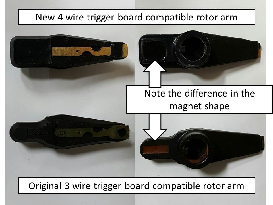
The kits came with a new rotor, and that was a;lways a mystery to me. The 3 wire and the 4 wire both use a magnet for trigger, but one has a round magnet, and the other is a square magnet, and I forget which magnet goes with which board. BUT, I hav enever understood the reasoning, as a magnet is a magnet, shape means nothing. Just my observation on that, as I have no proof either way. Mine all had rotors with strongish magnets, like yours, and 4 wire boards, and both shaped magnets, and worked just fine.
Since you have the workshop manual, I suggest a test of the throttle switch, as that concerns me some., BUT, a dead board may prevent it "talking"to the ECU, but I seriously doubt it.
Thanks for the encouragement.
We have contacted SNG Barrett. They have a replacement Trigger Unit. Priced at $193 US.
I am not sure who makes their replacement.
Our plans/next steps.
1. Repeat the test we did yesterday to be certain we had the ignition switch on for the tests.
Double checking our work.
2. Determine what voltage or signal come from the ECU to the Trigger Unit.
Is it a voltage?
3. Determine if the voltage or signal passes thru the trigger unit to the throttle switch (Capstan)
per the wiring diagram.
Pardon my premature send.
As you pointed out, turning the throttle switch should create clicks if the voltage/signal is
passed thru the trigger unit to the throttle switch. These are separate circuits and contacts.
I would think it should be voltage which goes back to the ECU to activate the injectors.
I forget the path, but memory?????, has me going to the throttle switch is indepent to the trigger board.
My reasoning is an XJS here many years ago that people could not start, so I got the puzzle.
The trigger board was missing, but I seem to remember I still got some clicks as the throttle switch opened, not all of them as the switch was sad, and a good clean sorted it.
I will ponder this over lunch.
Maybe my mate is home, and I can get as his PreHE, and do some tests, dunno.
Sorry to confuse you
Further explanation of my question of the signal from the ECU question.
From Circuit Diagram below I have taken a portion of the circuit.
It appears from the diagram that pin 12 of the ECU (14) is connected to the center pin of Trigger Unit (11).
It's relay contacts must then connect the Distributor timing back the ECU on one of the two outside wires on
the trigger unit.back to pins 21 or 22 of the ECU. The ECU would then signal the power Amp to
send signals the appropriate injectors.
Also the Trigger Unit single YB wire is then extended to pin 12 of the Throttle Switch (12). When the
throttle switch is turned (accelerator depressed) the throttle switch then sends the signals on the some
of the other four Throttle switch wires to the ECU to send additional (accelerator) pulses to the injectors
fuel for acceleration. Looks like the input for the Throttle switch goes thru the Trigger Unit.
I was wondering if I can trace the ECU wire pin 12 thru the Trigger unit to see why we do not get clicks
to add more fuel when Throttle switch is activated.
What voltage levels or signal does the does the ECU send and receive?
I wanted to trace the wires and signal levels. Can I just look for 12 Volts?
The trigger board simply supplies a pulse signal to the ECU, which in turn signals the EFI Amp to fire the 4 banks of 3 Injectors.
Mate was not home, found the spare key, and raided his Jag. Unplugged the trigger board, Ign ON, Engine OFF, "click, click, click, as the TPS is opened.
Plugged the board back, fired straight up.
He will never know.
This is the pin out chart I did a while back, finally found it in the cyberspace thingy.
I am thinking, SADLY, you have an EFI loom issue. Age is against them now.
The trigger board, if it clicks (yours does not), with Ign ON, Engine OFF, should click the Injectors with the magnet waved over either end.
These D jetronic engines will start and run comfortably with the TPS unplugged (since this happens so easily), as the splices I mention in the PDF are all on the chassis loom side of any plug connectors.
The Injectors are fired by the ECU/Amp, earthing the 12V circuits, hence the 12v on both sides of the Injector with Ign ON. The HE is the same, but being Digital, the items are smaller, and their "Amp" is in fact replaced by the Resistor Pack, but still Earth triggering.
Simply put, the trigger board supplies a pulse to the ECU, it in turn triggers the EFI Amp, and it fires the Injectors. The TPS is an enrichment "type" item, coz every time the internal wipers pass a segment, they trigger the Injectors, Simple. Hence the ability to drive with the TPS unplugged, if you are a "granny style" driver. I have done this. MILES from civilisation, the mighty V12 lost its acceleration OOMPH, but still ran just fine. Could not see a thing, 2AM, so with engine still running, drove the 300kms home, just had to treat the gas pedal like egg shells. THATS when I found the TPS plug had dropped out inside the boot cover, not visible, as I said previously, it does happen.
Last edited by Grant Francis; 09-26-2019 at 06:16 AM.
Update.
Further investigation and testing shows we do have a four wire Trigger not the three we thought.
The fourth wire, had the +12 connection was neatly hidden below the other wires to a switched +12 volt source.
The other three wires back to the connector which goes to the ECU were different colors and tracers than
the circuit diagram. We believe the trigger boards has been changed or is a later model. Apologies for the erroneous information.we gave previously.
The rotor has a small square magnet on the under side. Is this a correct magnet for a four wire trigger board?.
Further testing with distributor cap off and ignition on and the starter engaged indicates we are not getting pulses.
back to the ECU. Measured with an analog Volt Ohm Meter.
We removed the trigger board from the distributor and looked at the underside. The screws came out easily and
it was easy to remove the unit and wires. We took the Trigger unit back to the electronics bench to test it. .
We traced the wires and measured continuity from all four wires to the circuit solder connections on the under side.
At first it seemed like the power wire did not have continuity to the board, but after several measurements all seemed
corrected..
Next we put +12 Volts on the power wire and Ground on pin 12. We used a small magnet to moved over the top
side of he Trigger unit but, could not detect the pulses on the other two trigger wires using a volt ohm meter (VOM).
It seems like the "HAL effect devices" on this Trigger board are not working. Perhaps we need a stronger magnet.
In any case we have ordered a new Trigger Unit and matching rotor from SNG Barret. $US 193.
We appreciate very much any comments and suggestions.
Regards,
Denny O
Below are pictures of the Trigger Units (3 and four wire units. Also pictures of the different rotors.
That 3 versus 4 hiccup, is lack of BEER, and we V12 people ALL unnderstand. Others will not understand, and look on us as strange.
I have not seen a bad 4 wire, but anything can happen with electronic items.
I think????, the square magnet is related to the 4 wire, but honestly forget. One of mine had the round magnet and ran fine, and I always thought "a magnet is a magnet, regardless of shape".
I use a simple "Magnet on a stick", which I get for about $8 at any Auto Parts Store.
With the Ign ON, Engine OFF, and a quiet area, waving that magnet over the ends of the trigger board should have the Injectors clicking. The old 3 wire unit operates the same, BUT, you can actually hear the reed switches clicking.
Back to testing the 1978 Jaguar again.
We removed the trigger unit and the rotor.
Clearly it is a 4 wire unit as you said.
We tested the trigger unit on the bench.
- We powered the Power lead with +12 volts and grounded the center ground lead.
- Next we turned the rotor in the trigger unit.
- When the magnet passed over the sensors in the trigger unit we could measure a resistance change
to one of the outside leads. .
- Resistance changed on trigger lead back to the ECU. This trigger unit appears to be good.
Next we identified the Opus Ignition amplifier Unit and the Power Amplifier Unit.
We were looking for one unit, but they are separate Units. Diagram confused us for a bit as it shows
both units together.
If the Engine runs nicely on cold start for two seconds, can we assume the Ignition amplifier is working?
Next we traced the +12 power and ground wires from the Main Relay to the Power Amplifier.
+12 from the main relay to the Power Amplifier is good.
Ground to the Power Amplifier is also good.
We intend to reinstall the trigger unit to ensure we have it back together correctly and then
test to start gain.
Do you have any recommendations for further tests?
There are two separate connectors to the Power Amplifier, one has four wires (the inputs, power and ground.
The other goes to the injector distribution. Can we test for injector pulses to the Power Amp with an LED test lamp?
Also any hints about why we hear no injector pulses when we turn the throttle switch?
We will test the throttle switch next.
If the engine breaths fire at all, there is spark, and that is GOOD.
The ONLY connection between the Ignition and the Fuel systems on a D Jetronic is the trigger board pulse, which, among other other things, the EFI ECU uses as an engine speed reference, keeps the fuel pump alive, and signals the Power Amp to fire the Injectors. Which I have worked out (found my Bosch school notes from 1969 for another member) is A bank via one end on the trigger board, and B bank with the other end.
The opening of the Throttle Switch fires ALL 12 as the wipers pass each internal segment. This is how this system richens the fuel mixture slightly as the driver accelerates, to prevent a lean burn backfire. Apart from the wiopers inside that throttle switcm, there are "switches" that are used as direction (you dont want Injector pulse as you decelerate), etc.
NOTE PLEASE.
All this Throttle Switch info is from memory, and very OLD notes that have faded, and been lunch for mice etc. Most are beyond revival. I am working through the 400 odd pages to reconstruct what I can for the Forums. I dont have a throttle switch here, and the Pre HE I had access to is no longer accessible.
There is a test procedure for the Throttle Switch, and I will go looking and post it when I find it.
TRIGGER BOARD.
The 4 wire units I have had, and needed to "test", was very basic. Ign ON, engine OFF, QUIET PLEASE, and wave the magnet over the end of the board, CLICK, (injectors, not the board) OK. Now the other end, CLICK, OK.
NO click, board or loom issue. You have eliminated the board in my opinion, so signal to the ECU, and then ECU to AMP is all that is left.
BECAUSE, the D Jetronic system will run with the Throttle Switch unplugged.
I will keep thinking and reread this thread, and come back if I get more lights in the brain.

 09-17-2019, 11:45 PM