When you click on links to various merchants on this site and make a purchase, this can result in this site earning a commission. Affiliate programs and affiliations include, but are not limited to, the eBay Partner Network.
Whilst I have some new TWR cylinder head castings, TWR Group A and Group C heads + the Group 44 special casting heads (SP1 spec) and California (CA) heads I have for some time been aware of certain limitations, not the least that I have no wish to modify further the California Heads that I have and which I consider to be the best of the lot; they were also few in number and there ain't going to be no more of them. Nearly forgot the Broadspeed heads I once had with the moved valves to optimize the size and the sleeved inlets where the waterways broke through. This may be fantasy land for most but where there is a will there is a way.
Well aware of the costs involved I have been searching for a production method which did not involve new sand core tooling. Whilst the huge cost was a major factor here, upto 100K for both heads, so was the desire to have the ability of casting different port sizes for individual applications not realistically possible with the conventional sand cores.
The last batch of TWR casting produced had thick walled small ports to allow machining out to whatever was required, also the deck was thick to allow a variety of options here. The end result is that if you wish to have large ports then a huge amount of machining, and skilled machining / porting is required. Just do the maths, how many hours to open a port out by 4, 6 or even 8mm Skilled labour or even paying for a CNC program to do it! then multiply that by 12 and add another bout of CNC for the exhausts, not as much machining here mind you but again multiply by 12. Then not too much change out of 2k per head for the casting machining. It all adds BUT..... having done the maths if you could save on the porting the cost saving would be considerable. Add to that the possibility of making heads to order with ports the size required and wall thicknesses to match......
So its high level AutoCad time and a few other improvements added that only CAD can achieve. The manufacturing process lending itself to custom components is 3D sand printing of the cores and I already have a foundry that produces perfect castings in LM 25 or whatever they advise me. They have the experience and expertise and they already make Aston heads.
We have looked at integral cam carriers but that would be a step too far for most and would prevent such heads being used in many applications including FIA events. I do like the idea especially as it is possible with this manufacturing technique and offers a saving in both machining and the number and length of studs required. Perhaps a pair like this for myself when all is finalized is realistic.
We start from the original TWR engineering drawings, watch this space! .
I was offered these heads maybe 15 years ago with the cam followers, I have no doubt the heads are CA. However given the present location (cost of transportation + import +UK VAT.) The asking price and a problem with the heads that I wont go into here, I wont be going for them. Its simply a business decision.
I can easily see how such heads, once made, could remain on the self through lack of customers years ago. But times have changed just a little. There are no TWR heads available that I know of and even if there were they would be later spec designed not for maximum power but with smaller ports to be economical when 'running to the fuel' at much lower revs. The last 5 years were all about running within the fuel formula. who wants that nowadays. If anyone does I have the castings.
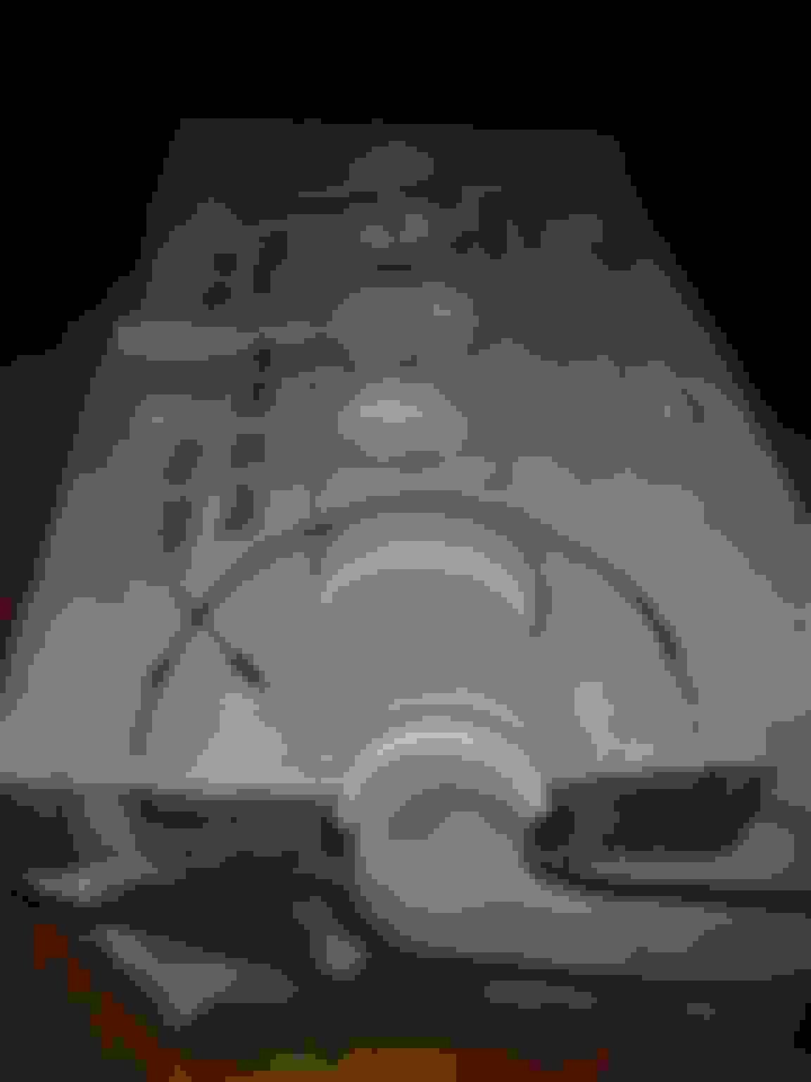
Ever wondered what a Jaguar v12 head looks like without valve slugs & ports? This piccy lets you see the basics & how we are putting them together on CAD. Original engineering drawings are essential here to get everything in the correct place, we also need to develop 2 sets (actually more but thats another story) of 3D files side by side, one for the new castings and one for the complete machined up head from those castings, no good having beautiful castings if machining makes thin areas or even break through.
the design is basically sound but..... look how the wall thickness of the port is thin on the TWR heads but only on one of the ports shown.
Facinating trip in the minds of the TWR engeneers at the time. I can understand the interest and desire to improve on it. Deconstruction will offer a perspective few have. I admire the focus and dedication. I for one am much more pragmatic and would simply choose a later platform.
Last edited by icsamerica; 01-02-2018 at 07:45 AM.
Brilliant work, terrific strategy. And who knows, as OEM heads get rarer and rarer, over time there may be a steady trickle of orders from all sorts of sources.
I like this. I'm never going to be a customer, but I have been working with quite similar methods in a previous job.
I was designing racing twostrokes for karting. In the beginning aircooled, but later also watercooled. Performance of these engines depends so much on scavenge port design, so it had to be precise, symmetric and not least easy to try something new as this moves almost as fast as F1...
We were using permanent mold casting method: Aluminium gravity molding in a mild steel mold for the outside shape combined with sand cores for the ports/ducts and details we wanted to be able to change easily.
We made the sand cores in seperate 'molds', and here comes the smart part: We did these sand core molds in some kind of plastic using CAM machining instead of using the traditional approach involving castings of castings and manual adaption.
These sand core molds were therefore really easy to make, and we could produce up to at least 1000 cores before they were showing signs of wear. That should do for V12 head production as well.
I also have some recent 3D print experience, and to be honest: I don't believe you can live with the surface quality that can be achieved, and the support structure needed during printing will also become quite a task to remove without (to many) traces.
ICS that�s ironic when you have chosen an XJC and SBC. Hopefully XJR5006�s work leads to aftermarket heads being available to V12 owners in a similar way to you having aftermarket heads on your SBC. Anyways I don�t think lumping an XJR race car is a good option here.
Ps don�t get me wrong, I�m a big fan of your coupe.
Originally Posted by icsamerica
I for one am much more pragmatic and would simply choose a later platform.
ICS that�s ironic when you have chosen an XJC and SBC. Hopefully XJR5006�s work leads to aftermarket heads being available to V12 owners in a similar way to you having aftermarket heads on your SBC. Anyways I don�t think lumping an XJR race car is a good option here.
Ps don�t get me wrong, I�m a big fan of your coupe.
Thanks That's kinda of my point. Available...when? Time? Life is short. I'm on my 3rd coupe project and this v12 head talk has been going on for years. BTW... There's a 2018 coupe project in the werks. Got the coupe...Still gathering other parts. Haven't chosen an engine yet but it will have a T56.
That's said any comment on these vids. Seems like a Aj16 headed 6.0 would make 420HP first go round. Aj16 is highly reguarded and head is design is probably good. I guess it all comes down to where to you want to put your time and money...at the CNC/foundry or fabbing drive gear, intake and exhaust manifolds.
" Available...when? Time? Life is short. I'm on my 3rd coupe project and this v12 head talk has been going on for years."
I have new original TWR race head castings 'on the shelf' already. I am however very aware that there is a huge amount of machining involved in turning the castings into usable heads, read this as a BIG lead in time for such things as the basic complicated machining, which is undertaken by the original machine operators now working part time in their retirement at the original machine shop. These old boys manually machine the original castings from the original diagrams using 'best fit' of the castings to the drawings. This is the old way of doing things and there is little future in it.
Then its another machine shop to get seats and another for porting and another for the fitting of guides with the waiting time between all of course.
We have already been here re-manufacturing the TWR Big cam carriers and cam covers.
Now we CNC them and have added and made alterations to the original tooling so that we can actually use a 'zero' line and get a functional product at the end without our engineer having to continually adjust things due to inadequacies in the castings. I hardly find it acceptable, even on a custom race engine, to have a wall thickness less than 1/2 of what I would ideally want.
So to have any future we needed to move over to CNC machining rather than DRO. We then needed to see how to produce a superior casting with guaranteed zero lines to enable safe and accurate CNC machining without the 'best fit' adjustments of the originals. To put it bluntly I like a lug to have a hole in its center including the countersink not at the edge barely avoiding break through. It may be acceptable to some to simply move the hole to the center and do the same to the matching component or make best fit over both but I am looking at repeatability. So its lots of very careful modification to the original tooling (expensive) and you still end up with a casting in the old style, small ish ports with very thick walls to allow machining for whatever size ports the customer wants (expensive) and the original faults of the design carried over. For example both Group 44 and TWR ended up with air bleed pipes from the high points of the heads water jackets.
So with these various matters needing addressing we are revisiting the whole design again; dont get me wrong here, we are still going flat head and looking for all original mounting points basic looks etc. but.... why do the 30 degs in the water jacket when 32 will allow air to gravitate to where the outlets are why do the hole outlet area flat internally when an internal slope can aid flow to those outlets, but when you start going in this direction you suddenly realise a revamp of the original tooling may no longer be the way forward, so why not go the full hog and CAD the heads with all these revisions why not make the heads custom per order incurring the cost of sand printing the cores but loosing the greater cost of porting, clearly a port wall thickness to match the port is much nicer system and avoids the risk of breakthrough on larger port engines. We are even able to add internal surface spikes, cones ridges, call them what you like, to increase the surface area by the combustion area and exhaust port allowing superior transfer away of heat. Maybe you get the idea now...I know the flat head is not the best design as evidenced by the huge spark advance required so I am even looking at twin sparking to increase efficiency and torque, don't know if its possible but I will soon know.
Its a brave new world out there and I know there will be few customers but hey some guys are making twin cam heads and fitting superchargers!
I have a pair of original twin cam head btw, maybe later I will get those put on CAD to give yet another option.
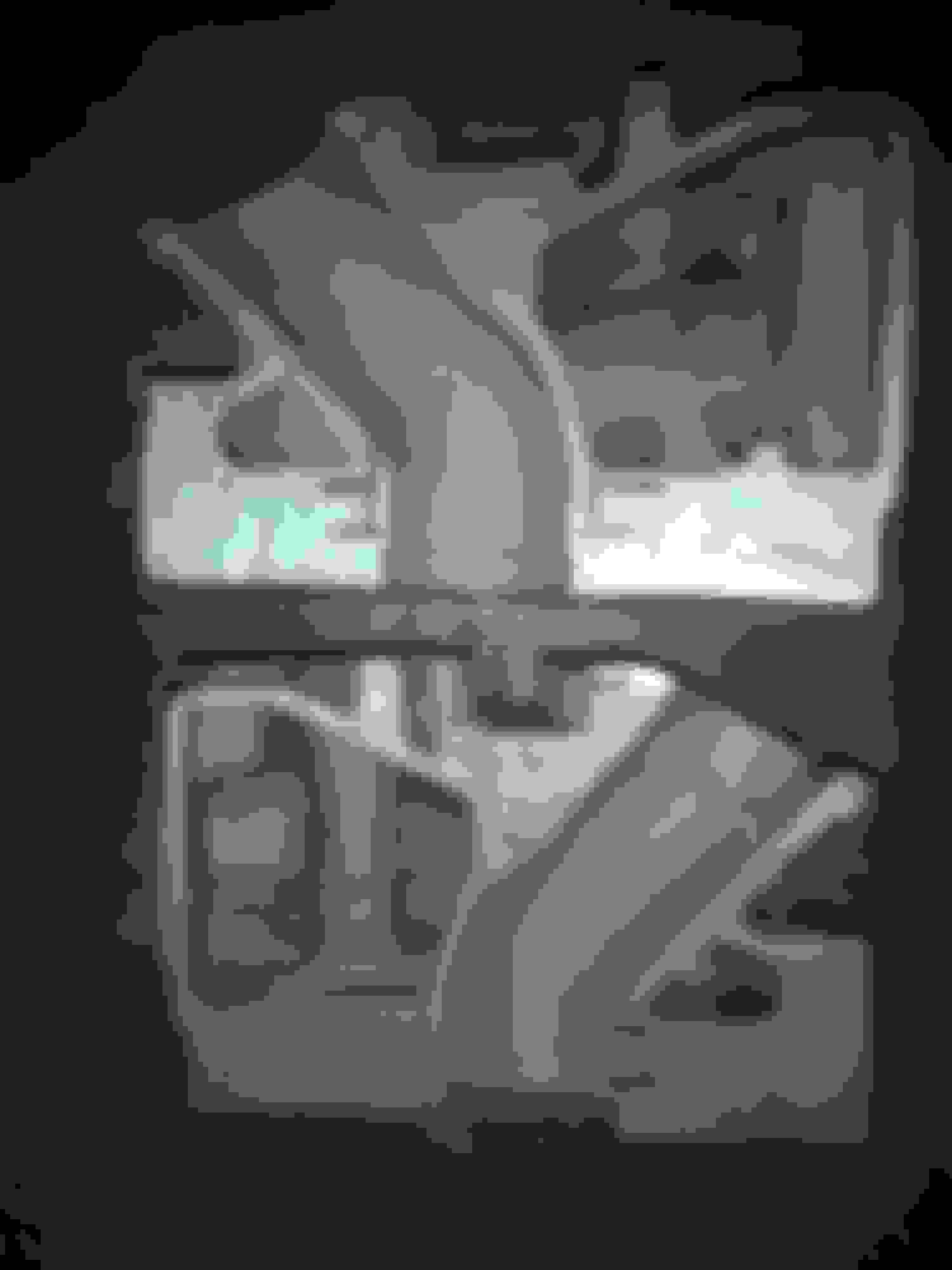
Here is an example of what we want to design out, the dangerously thin wall at the inner curve of the exhaust port, the excessively thick outer curve thickness which also severely restricts the waterway by the plug blip not only that but the area cooled at this critical area. Far better to let CAD place the port in the desired diameter with a uniform wall thickness, just a light polish required to finish.
BTW this is a CA head which is arguably the very best of all the offerings
great cutaway.... I bet that thin wall on the exhaust side is causing localized hot spots and boiling which hinders flow. Also the exhaust port is too long allowing too much time for heat transfer. Ideal would be to have the exhaust port short and intake port long.
exactly what he said,, back 1994 when building my V12 , i had the exhaust ports only,after porting by hand, i sent heads out to have exhaust ports themal coated , along with the head deck surface coated! i also use 3MM oversize inlet valves, 2MM exhausts.
for that exact reason ,heat transfer from long port into cooling jacket, to reduce hot spot possibilties, and reduce heat from the open deck design!
the old SBC had serious from there beginning, center exhaust ports siamesed!
i have never had heating problems, in 100+F temps!
i dont really know if it helps or hurts, i have always just did things that made sense to me,, 65 years of hy-po engines. and i like stepping out of the box ,that most are caught up in!
Suddenly I feel like I am attempting to reinvent the wheel. Here are piccys of what has dropped into my lap, No information with them, But just a look says everything to me. Port size before cleaning up appx 42MM !!!! and just about all the little things I was concerned about or wanted to improve have been done.
Specail Castings Heads maybe the ones in A Scotts book for discussion ????
They say a picture says a thousand words....
Hows about 42mm/43mm inlets to begin with and no weak thin points in the port walls.
Anyone with ideas or knowledge of these heads do let me know.
The second set of sectioned heads are from Jaguar but not at all like the TWR heads, they are similar to my CA heads except that the deck is very much thicker. The special castings are clearly marked for consideration of the longer stroke cranks pushing the pistons into the recesses in the heads AKA the TWR 7.4 engines. However the ports are too large for TWR and the ever reducing fuel allowance which necessitated smaller ports and lower revs.
Our idea is to produce heads very much like these but with a choice of inlet port diameters and the option of moving the exhaust and inlet valve very slightly to maximise flow area around the inlet. Nothing new here, Broadspeed did this 10 years earlier.
something that just came to mind, when doing my Pre heads, i gave a lot of thought to the overheat problems V12 jag.
and the internal cooling head jackets surface areas, for heat transfer into the coolant!
i set up an old bathtub porcelain coated!
set the head on some wood blocks ,deck surface up, blocked off as many holes into the coolant area, and poured straight Muriatic acid ,filled it up , lets set couple hours, then with a small rubber blade pump forced new acid in one end you should have seen the crud, crap, sand, chunks of stuff coming out the other end!
then flush with plenty hot water, finish off with some Sodium Bicarbonate solution!
my assumption is it increased the internal surface area!!
yes i know(i'm outta the box again,story of my life), but been 23 yrs and never an overheat and also no problems!
came up with this factory exhaust port drawing , showing a 90* angle ,preHE,!
anyone got a profile pic of the HE, seems it maybe even tighter angle?
the pic that 5006 shows of the Cali. Grp44 exhaust shows a much better angle! altho thin wall at the short turn seat angle.
i think that port is what we in states refer as a raised port(higher up on the exhaust side, common on BBC & SBC, both inlet & exhaust, it became a must do thing in later years).

 01-01-2018, 03:54 PM