When you click on links to various merchants on this site and make a purchase, this can result in this site earning a commission. Affiliate programs and affiliations include, but are not limited to, the eBay Partner Network.
The normal way to check the pinion preload is with nothing else in mesh, so the crown gear and axles have to be removed. Then you are measuring the drag on the pinion bearings only, and you're aiming for around 20 inch-lbs.
A second way is to mark the nut relative to the flange, loosen it off and then tighten to specification. I forget what it is, but plenty. You will need the flange holding tool and a long breaker bar to be able to exert enough force to tighten the nut.You have to do this by hand, you can't use an impact wrench. It should come back to the previous mark, but also there is a crush sleeve in there for generating the preload, so if you overtorque you can't back off the nut. The diff needs to be stripped and the crush sleeve replaced.
Yes, undoubtedly a Watts linkage would help. On the jag, the radius arms are there to prevent rear wheel steering caused by the whole IRS assembly moving under torque. It's amazing how much compliance there is in the mounts, so a way to control that motion is necessary.
My guess is your pinion mesh and/or backlash is incorrect, and that is what's causing the whine. It's possible that it's out of mesh because of bearing wear and a set of new bearings will cure everything, or it needs to be rebuilt. It's possible to rebuild it at home, as you have the manual. You must follow the instructions exactly, and make sure everything is in specification. You'll also need to be able to measure accurately to 0.001", and a vernier caliper isn't accurate enough.
Pinion depth is the critical first setup, if that is wrong, you'll never be able to get backlash and side to side carrier clearance set correctly - you'll only be able to set one, and not the other. The shims also go behind the carrier bearings, so you need a special bearing puller and a press. Anything other than the right clamshell type puller will destroy the new bearings. Expect to have to press the carrier bearings on and remove them several times to get the shims correct.
I�m sorry to be so blunt but you really don�t know what a Watts linkage is. The purpose of any watts linkage is to keep the differential centered in the chassis through suspension movement.
Jaguar since the late 1960�s has all been IRS which means the differential is rigidly bolted into the case which is in turn bolted into the chassis.
All a watts linkage would do in that case is make service more difficult. And add needless weight.
Now perhaps you are thinking of a rear sway bar ( which is an entirely different thing and different purpose)
Do be careful about adding one. It will increase under steering. We racers balance the front and rear sway bars, for absolutely optimum cornering power but most often like the factory the rear sway bar is minimal and rarely improves cornering power. Which is why they were made smaller and smaller throughout production and eventually left off completely.
Based on that photo your car will not have any rear suspension movement at all. That system won�t work at all.
If you draw a line of the two arc�s involved the wheel arc and the drag link arc they are 90 degree to each other. Effectively limiting movement to wear and slop in the connections.
If you want it to work?! That chrome link has to be exactly aligned with the inner pivot point of the lower axle arm. ( exactly) bring it forward ( or rearward ) at about a 45 degree angle. Yes a new bar will be required.
Finding those exact spots is simple I�ll explain if you wish.
Google Lister rear suspension if you�d like to see this before doing it or having it done.
By the way. If the suspension is rigidly mounted you will hear and feel the rear end much much more than a regular Jaguar which is completely rubber mounted. That rubber not only allows the suspension to work but effectively isolates noise and vibration.
Gav
Thanks for the clarification. On the jaguar axle it is important, if the longevity of the system is a consideration, that the lower wishbone is supported at its outer end to feed acceleration and braking loads into the body. If not, the entire force of (for example) braking the car from 120 MPH to zero, as far as they are fed through the rear axle, is taken by the inner fulcrum bearings which are about 1/2 inch diameter roller bearings that are ONLY designed, and only strong enough, to take the up and down motion of the wishbone.
All you need on your solidly mounted setup is one arm going forward at about 45 degrees to the centreline of the car, from the outer end of the wishbone, ending each side in line with the inner fulcrum bearing line. If done 100% accurately rose joints will work fine, but honestly a rubber bush to give a touch of compliance and allow for slight inaccuracies is best. The triangle thus formed between the axle, the new arm and the line between the fulcrum bearings and the end of the arm, thus forms a triangle that can move about its inner axis with no binding as the suspension moves. Diagram attached. As long as the fixings at points A,B,C of the triangle are in the same horizontal plane, the suspension will move up and down with no binding and the acceleration and braking loads on the axle are fed into the bodywork. The point of having a rubber bush at point C is to allow for any slight inaccuracies in the construction by having a bit of "give" in the geometry. This is the exact setup that TWR used on their racing XJSs in the 1980s.
In the standard axle the loads go straight forward from the hub (ie not in a triangle pivoting about the line A, C). This would mean, if there was no rubber in the fixings, that the geometry would cause the system to bind as soon as the suspension moved.
Well said.
The needle bearings are overloaded and tend to wear causing looseness. That leads to a bit of rear axle steering in very short order. I eliminate that possibility by using a bronze bushing to replace those. I carve a slight grease path to provide grease all the way around. You can actually feel the difference at the axle end as you cycle the axle through its path.
Hi,
had a chance to get car on stands and looking at chassis I'm goosed....
the inner pivot of the LCA if extended forward goes straight into chassis frame. So I couldn't get a rose joint or anything forward of the diff at the same height and in line with the inner pivot.....
I could get a rose joint in line about 2" lower but I guess that wouldnt work...?
leaves me would a watts link work ? But going straight forward and back pivoting at the LCA original radius bush mount?
Regards
gav
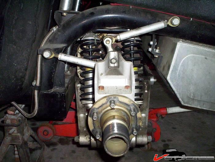
The inner fulcrum (circled in blue below) does not look to have a chassis rail near it. Have you got a photo showing the problem?
Your axle seems to have two reaction rods (underlined in red). If these were solidly mounted the axle would not move freely. How are they bushed? If they have a bit of "give" via some ruber bushes then they should support the lower wishbone adequately. If not how is the axle movement accomodated?
Hi,
had a chance to get car on stands and looking at chassis I'm goosed....
the inner pivot of the LCA if extended forward goes straight into chassis frame. So I couldn't get a rose joint or anything forward of the diff at the same height and in line with the inner pivot.....
I could get a rose joint in line about 2" lower but I guess that wouldnt work...?
leaves me would a watts link work ? But going straight forward and back pivoting at the LCA original radius bush mount?
Regards
gav
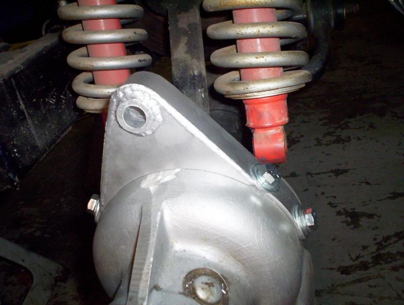
Tubes are welded in the base of the chassis to support the front of the lca and a nut at other side of chassis inside the tube to tighten. I can't get a rose joint in front of the tube that is welded in the chassis
regards
gav
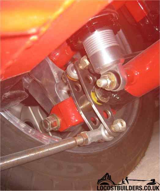
ps the red picture is another cobras idea with a different chassis as said in previous post
If you are attempting to replicate the racing rear suspension it goes from the outer drag link forward at about a 45 degree angle to intersect the inner pivot point. The rose joint goes straight forward into a short tube. And the forward rose joint goes sideways towards the outside rail. On a short link. They are connected by a piece of tubing at about a 45 degree angle.
There are pictures of it on the internet. I think TWR used that approach.
Hi,
Many many thanks for those. In my looking for a better solution I did see those videos. Unfortunately I can't fit anything in line upfront like he has as the base of the chassis is there.
regards
gav
You cannot use the drag link. It will effectively eliminate any suspension movement.
I see the lower suspension link has triangulation. If you don�t plan on any hard launches you can eliminate the drag link entirely. Then the suspension will work.
If you get carried away and do a hard launch chances are the lower link will bend and instead of pointing straight ahead the rear wheels will cause the car to want to turn even when the steering wheel is pointing straight ahead.
Well, a Watt linkage as used on a live axel constrains the diff center line to move in only in the vertical with no possible movement in the horizontal. The mechanism spun 90deg and applied onto each lower control arm provides the same constraints allowing each arm to move only in the vertical. Side to side movement is constrained through the diff mounted to the cage and 4 mounts to the body. Packaging would be one of the concerns in choosing between the Group44/TRW extended A arm setup that prevents twisting of the cage, or dual side watts linkage to constrain the control arms.
A Fore and aft Watts link would not work either. The arch of the rear suspension would conflict with the the arch of the watts link effectively locking up the suspension just like a rigidly mounted drag link.
If everything is mounted on rubber like a stock Jaguar the rubber flexes enough to allow it to work.
But when things are rigid you cannot use the two different arches per side.
As things stand remove the drag links and the suspension will work. Just avoid hard launches.
Well, a Watt linkage as used on a live axel constrains the diff center line to move in only in the vertical with no possible movement in the horizontal. The mechanism spun 90deg and applied onto each lower control arm provides the same constraints allowing each arm to move only in the vertical. Side to side movement is constrained through the diff mounted to the cage and 4 mounts to the body. Packaging would be one of the concerns in choosing between the Group44/TRW extended A arm setup that prevents twisting of the cage, or dual side watts linkage to constrain the control arms.
~Paul K.
AFAIK, open to correction as always, A Watt's link still relies on rubber bushes at its fixing points on axle and chassis. Without these it would prevent any up and down movement of the live axle. So, even if installed fore and aft and attached to the lower wishbone, it would provide no benefit over the jaguar OEM radius arm.
Well, although a Watts linkage *could* use rubber in the joints, I see no reason why it has to. For the swing arms it probably DOES need rose joints at the chassis mount ends so it has the ability to move through the slight arc the swing arms make though, with a bearing for the pivot on the swing arm:
I'll just throw in that you are probably using the differential solidly mounted to the chassis, about a foot away from your butt when you are in the car. You will certainly hear noises that are not heard when it is on a rubber isolated subframe in the Jags. That said, most normal diff noises are at certain speeds, not the wide range that you describe. I suspect you have a rough carrier bearing.
On the subject of the lack of trailing arm or Watts linkage, I think you would be better off with one or the other but if other cars have used the Jag suspension without either, clearly it's not essential. It does seem that it would allow some amount of toe change due to flex. The watts linkage would be best, it would keep the wheel in a straight line, no toe change as the suspension moves up and down as you would get with trailing arms. Also, the watts linkage looks really cool.

 07-30-2022, 11:08 AM