When you click on links to various merchants on this site and make a purchase, this can result in this site earning a commission. Affiliate programs and affiliations include, but are not limited to, the eBay Partner Network.
I promised to keep the thread updated with my ongoing saga.
With the help of Six Rotors, who I am deeply grateful for all his help, it should be said!
Unfortunately, the hard drive on my SDD died a few days before it's the arrival of the replacement ECM/PCM and I spent a long time rebuild to version 149 - which was a waste of time because all the pinout and manual diagnostic checks require a Topix subscription where they didn't in the version 131 that is as previously using. So a side project to rebuild back to an older version less reliant on Topix will be my hobby for the next week or so. *hint hint*
The replacement ECU/PCM arrived and we attempted to swap it out and repgramme..no joy ECM Module Comms failure - same as before. So on the logic that two ECMs are not likely to be kaput, I am back to pinout checks; but i need SDD to guide down the ohm and voltage diagnostics, the later version SDD wants me to go to topic and download, my old version had it built-in.
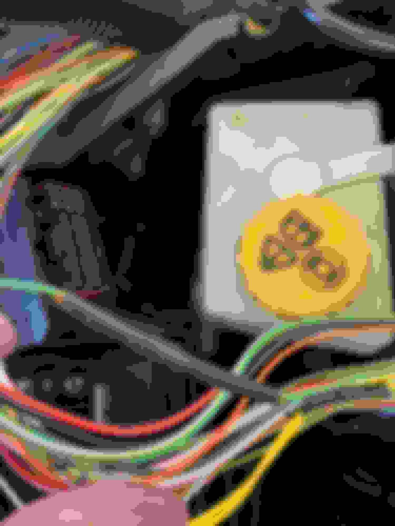
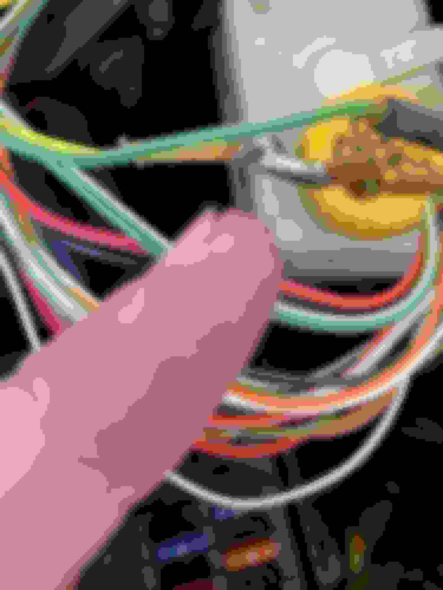
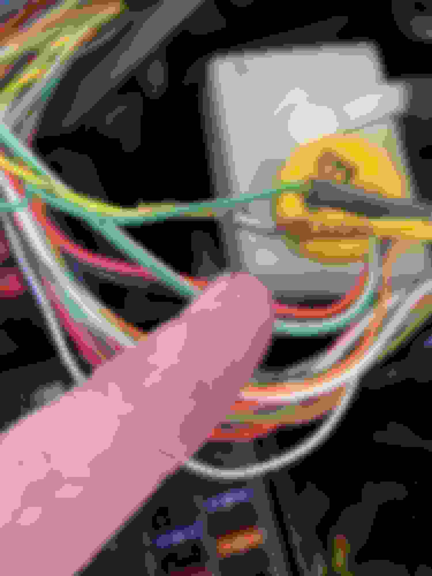
So I started looking back at the PCM connectors, followed the loom to a "big square connector with a bolt in the middle of it". Undid that bolt and split the loom, I took the sheathing of the loom to start separating the loom out and it looks to me like "horrors of horrors" that there are some canbus loom repairs from a previous owner. The yellow and green twisted wires have been split and soldered back at some point. I am suspecting this could be a symptom - perhaps a dry joint but want to make sure I have before and after stats correlated against SDD before I undo the damage and redo the soldering. In the photos, I have cut the heat shrink back to look at the repair.
More updates as they happen and things progress and of course if anyone's been there and done this, always happy to learn!
Small update: rebuilt SDD computer and got it working again with the Mongoose Pro.
Complete all the PCM pinout and voltage/connectivity checks. Everything appears on point within tolerance (which is frustrating TBH). It appears that the CANBUS resistances and voltages are within specs between the latched connectors and the engine harness too. It's a bit of a mystery why I have a PCM module comms failure so my next step is to recheck the OBD interface wiring pin by pin voltage and ohm settings per SDD.
After this step, SDD sadly gives up and points to a loom short or break - not looking forward to trying to find that!
Following with interest... but back to the title, what changed?
pretty much nothing to be honest, suspect that the battery died and was subsequently subject to a failed jumper cable start and eventual battery replacement. Ran great for about 70km following that and then just run me through the mill and story you see above. Yes, other batteries have been tried too - known good batteries.
All networks basically consist of electronic control mod- ules, connectors, the Data Link Connector (DLC), and data bus circuit wiring. The only repairs that can be per- formed are wire repair, connector repair, and module replacement.
NOTE: Always reconfigure/refresh a module’s software before condemning/replacing the module – ‘Software before Hardware’. Remember, the hardware physically or electrically operates mechanical devices, and the soft- ware processes information.
Network Service Tips
NEVER condemn a module until ground and power circuits have been checked using a digital multimeter
Use proper wire repair/replacement methods as spec- ified in the Workshop Manual
Always refer to GTR for specific information
Use only approved replacement electrical connectors
Repairing Network Wiring (Twisted Pairs)
Network harnesses consisting of twisted pairs of wires (CAN bus, for example) can be repaired as required. When repairing a twisted pair of wires, do not unwind the existing wires any more than necessary. Before com- pleting the repair, replicate as closely as possible the original twisting pattern on any new wiring.
The following points should be observed when repairing a network harness:
• All wire pairs must have at least one twist per inch (to resist electromagnetic interference) and must be twisted to within 10cm (4 in.) of the connected modules.
• Always use correct gauge wire when performing data bus repairs. High resistance in the data bus cir- cuit could result in network concerns.
• Only make crimp wire repairs. Solder repairs are UNACCEPTABLE.
• Use correct gauge of wire
• Use only Jaguar supplied connectors when connector replacement is required. This will ensure the correct fit and help prevent excess resistance in the circuit.
• In some cases it is unavoidable that a repair to a twisted pair harness, using crimped connections, will leave an unwound length of wire. The repair length should not exceed 40mm (1.6 in).
CAN AND SCP SPECIFICATION: 39 TWISTS PER METER (APPROXIMATELY ONE TWIST PER INCH)
688-JAG: Advanced Electrical Systems and Diagnostics Technical Training
OK so we know from the training manual solder is your enemy and the can bus wires are not twisted properly. We don't know if that subsequently destroyed a module. I suspect hope not but I don't know how long an untwisted can bus wire and soldered joints would take in an engine bay to crystallize and create too high of a resistance. Since you may not be able to obtain correct pins, and you may not have enough wire length to disconnect at the solder joint and connect to the distribution box. When repairing a twisted section, both lengths of wire must me the same type as the poem and the same length.
I think you're on the right track and even if not, that "repair" is not acceptable. I would take before and after resistance readings (before removing the solder joints and after properly twisting and crimping)
Thanks, Sean - I would tend to agree. I cannot tell when those soldered repairs were made, but I DO know it's not after May 2017 which is when I took ownership of the car. Of course - anything is possible and they could just be the issue, but at the moment all voltages and impedances are spot-on for the SDD diagnostic recommendations and pinout checks. I am increasingly suspicious of failure in and around the OBD port interface itself and the wiring to the PCM/. I suspect that the wires in the engine bay loom were cut and used as insertion points for diagnostic testers and signal injectors to trace shorts or other wiring oddities. This weekend my focus shifts to the OBDII port inside the vehicle and the plethora of fuses, relays and gubbins stuffed in the footwell walls.
I am sure it will be something so simple that it will be a Monty Python head-slap moment when I find it. I'm no missing too much at the moment, given that we're getting to Fall (Autumn) now, the car would have been layed up in storage for the end of October - the salt here in Ontario on the roads in winter is just crazy.
Should I get my Eureka moment, you'll hear my whoop of joy in the USA :-)
I wanted to update this thread after a year of diagnosis and under bonnet head-scratching. Despite the best efforts of multiple electrical experts, multimeters and oscilloscopes now fix was found. Family, work, and COVID got in the way and today I surrendered my toy to the auto wreckers for parts recovery and a donation to charity. I am sure had I unlimited resources that she could have been put back on the road, but to see her slowly deteriorate on my driveway made no sense. Here ends the story of my Jaguar XK adventure

 09-13-2020 | 02:02 PM