When you click on links to various merchants on this site and make a purchase, this can result in this site earning a commission. Affiliate programs and affiliations include, but are not limited to, the eBay Partner Network.
In common, it would appear, with other owners I have been having ongoing problems with my 2010 XKR (screen flashes four times when door opens but then blank all the time. I've changed the battery for an AGM (fully charged) to no avail so earlier today I plugged in my iSoft code reader. On the Infotainment section it showed two codes - UO159 (Lost Comms with Park Assist Module) and U1A24 (MOST ring complete. No Comm).
Whilst the screen isn't working the car does bleep when approaching objects in reverse so is working OK, but just no screen. I'm not well versed in all-things electronic and so am hoping that someone can advise me where to start looking ? Would a faulty park assist module render the screen blank, or is it a symptom of a faulty screen unit (or the screen interface module) ? I believe the MOST ring is a fibre optic circuit - is that the probable cause of my problems. Any advice would be greatly appreciated. Thanks in advance.
Then download the workshop manual here and it will show you where all the modules are located in the MOST ring. Use the bypass loop to eliminate each module one at a time until you find the culprit.
Manual can be found here: http://www.jagrepair.com/images/Auto...XKworkshop.pdf
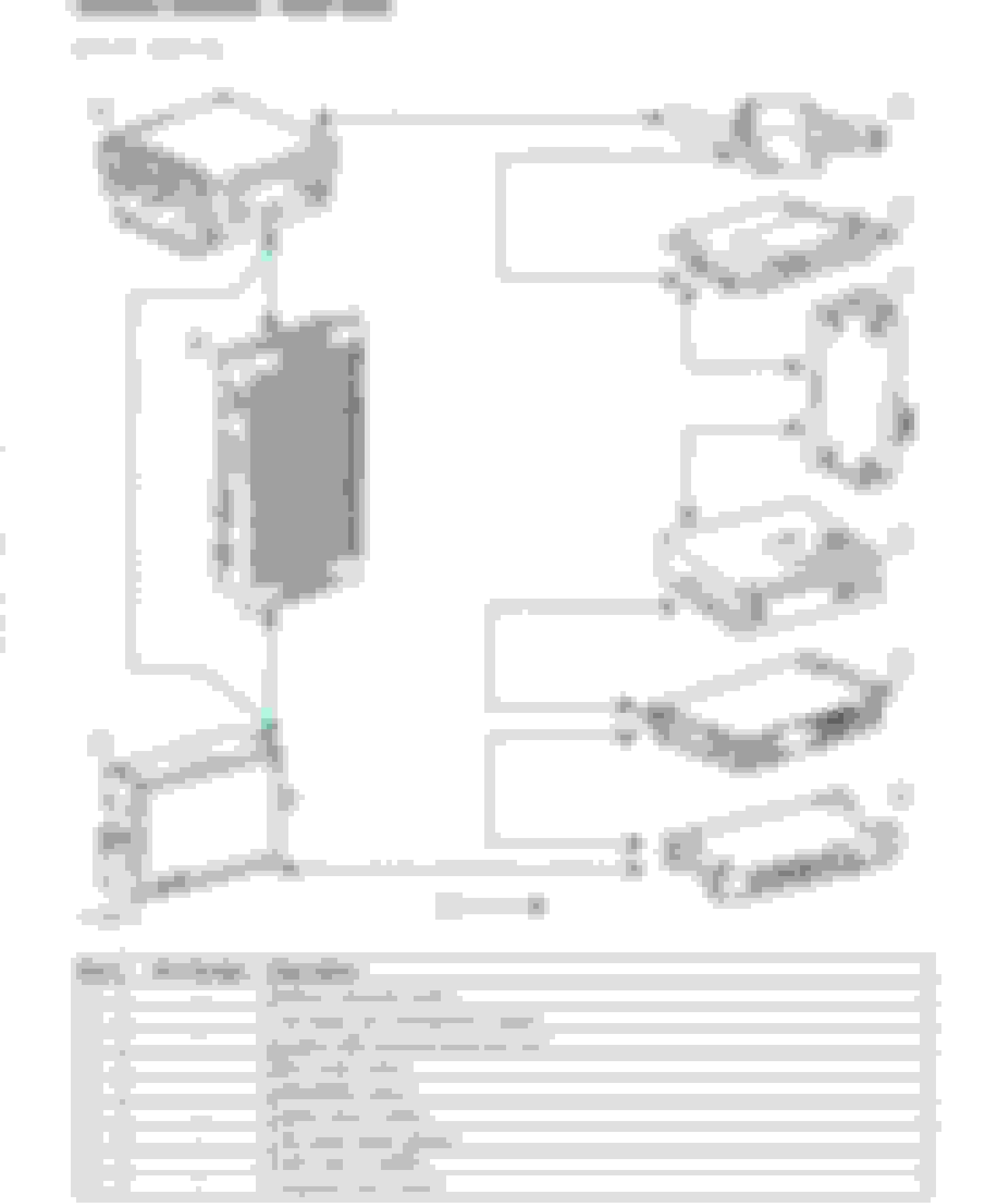
Here are the components in the MOST ring:
you may not have everything (DAB, AMP) for example in which case the MOST ring just moves to the next device. Once you find the offending module, check for power and ground first.
1= under the drivers side under panel next to the center console. It should be capped as is shown in the diagram - otherwise best to leave it be. It's intended for diagnostics and probably not the problem
2= on top of the CD slyer in the center stack (also known as ICM)
3=in the trunk near the taillamp
4=6 are on the trunk stack next to the battery one atop the other
7= obvious
8 = amp, under the passenger footwell
9 - CD player
U1A24 is a possible cause. Your code indicates there is a break in the MOST ring.
Just semantics, but if there was a break in the MOST ring, I think there would be a different code. Here the ring is �complete�, just some module is not passing normal communication signals, and your trouble shooting method is still the right thing to do.
Ugh. �check MOST ring for circuit break�.
Why not label this as �MOST Ring Incomplete� then?
Guess they just don�t know if it�s a connection problem or module problem.
Thank you both for your suggestions and help - it's really appreciated. I have ordered a loop tester which should be arriving tomorrow courtesy of Amazon UK. I did have the screen working (albeit at reduced brightness) a few weeks ago but then it suddenly stopped working altogether (other than the four 'R' screen flashes previously mentioned when door is opened). If there is a break in the fibre optic cable I'm presuming the best way to confirm same is to disconnect each module in turn and shine a laser down each fibre before checking for light at the other end on the next module/component ??? Another forum contributor had a similar problem and the workshop replaced the 'Interface Module', which cured the problem for them. After checking for fibre optic continuity I think I may try a replacement 'Interface Module' (I can always sell it afterwards to enable someone else to try). Ah well, it all stops me getting bored during this pandemic - lol !!!
I doubt a break in the actual fiber optic line would occur without interference from someone. It's more likely a module, but who knows?
When you unplug the fiber optic cable at any given module, you'll see a red beam on the input side if it's sending a signal so no need to shine a laser. The loop will just bypass the module and if you still have the problem, reconnect and move to the next module. I haven't heard of an interface module. Perhaps a nomenclature thing. Be aware, some modules are plug and play, others are not. You cannot just swap modules such as the ICM. It requires SDD. I think Touchscreen, amp and BT are plug and play. Others will have to weigh in on SDARs as I don't have that.
The numbered order in the diagram is the sequence that the FO cables run. You can start anywhere but should start @ #2 imo. That said, the BT module appears to be a common fail point and is easily accessed in the trunk stack....
Thanks Sean. The module I've purchased (used from a 35,000 mile 2014 car) is in fact number 2 on the diagram (Information and entertainment module). Should get the loop today so will try as you suggest tomorrow (fingers crossed). I'll update when all tested.
UPDATE: I've now ascertained that the problem with the MOST circuit lies between the MOST diagnostic connector (under right-hand dash) and the Information Control Module (sitting on top of Integrated Audio Module). The red beam, which is regular at all other modules (on for about four seconds then off for about one) is sometimes absent until I physically move the loom and then it gives erratic signals. Strangely, when the signals do occur the Touch Screen flashes with the 'R' symbol even though the connector is removed from the Info Control Module. The signal is good at the Diagnostic Connector and I have tried the same with the loop connected in its place, so the Diagnostic Connector is OK. The problem I now have is trying to find where the break/damage is to that section of the Fibre Optic Cable. I believe that it's possible to buy sections of cable with connectors at the ends - so I am looking at removing the offending cable from the connectors at each end and fitting same - at least I'll confirm my diagnosis (or not). Does anyone else have any suggestions - I welcome any advice. Many Thanks.
If I'm understanding you correctly, when you connect a loop at the ICM, you have a steady beam at all other modules but when you disconnected the ICM to loop it, you found it worked a bit only when you wiggled it?
I assumed you would put the bypass loop at each module and then re-run the diagnostics to see if the code cleared.
No matter - to address your question, used FO cables can be had on eBay.
You can re-use the connectors. Once you remove the connector cover you'll see a small blue plastic pin, that holds the FO line in place. Push it out and the cable slides out of the connector. Try it on your bypass loop so you understand in case I'm phrasing poorly. Be aware that each line is directional with and arrow on the connector telling you which is inbound and which is outbound. Personally, I'd put some tape on one and mark the cable so you don't miss that.
I think I'm over-tired today and, despite studying the MOST circuitry, failed to understand it properly. I now understand that the red beam emanates from the ICM and goes to all the modules in a clockwise direction (as per the picture in the workshop manual). Having travelled around the 'loop' it then finally returns to the ICM. Obviously (I now realise) if I pull the connector out of the ICM there will be NO beam whatsoever travelling around the loop. I have ascertained that the beam is good all the way around and back to the Diagnostic Connector. Having disconnected the battery (just to be on the safe side) I then shone a light along the optic cable going back to the ICM from the Diagnostic Connector - it did indeed shine at the other end and, therefore doesn't appear broken (despite my previous thoughts). I now believe that the problem likely points to a failed ICM ( I bought a used one a few days ago which should arrive soon). I'll replace that unit using SDD and keep my fingers crossed that it cures the problem.
Maybe this will help too from the 2010 onward wiring diagram. The "Diamond" location on each - Instrument panel harness is behind the center stack, The tunnel refers to the trans tunnel and the trunk stack is next to the battery. Amp is under the passenger footwell and I think iboc is near the tail lamp
Thanks Sean - I�m keeping my fingers crossed that when the MOST problem is finally sorted I�ll have a working Touch Screen (not worked properly since I bought the car (was working at reduced brightness originally but, more recently, not at all).
Sounds like you're confident in your findings.
I posted the MOST ring info from the wiring diagram for others who may need this thread. My process would remain the same as I originally noted. Disconnect one module at a time and loop it, then run the diagnostics until the U1A24 disappeared, knowing new codes might pop up due to lack of module, which is fine.
It's a slow process and you can speed it up by putting a loop at the point where the FO cables go through the rear wall, essentially eliminating everything in the trunk. If the code stays, you know your problem is in the cabin.
Am following as now my touchscreen (actually, the whole unit...stereo, etc.) all are cutting off and on at startup and do so until the car warms up or has been driven ten or so minutes.
Also following. My touchscreen and radio are dead-dead, happened a couple of weeks ago, none of the "fixes" work.
My car is at my dealership (great techs, good with XK's). As soon as I hear from them I'll reply on all the touchscreen threads currently on the forum.
Going to be interesting to see where this could possibly lead. For a time, Jaguar were requiring the failed TSD be collected prior to providing a costly supplied replacement and then, not long after, marked them as no longer available in the EPC. If these units begin failing globally, as I suspect is the root for many of these issues instances, I wonder what, if anything JLR will do, especially considering they are integral to the climate control functionality and also fitted to the larger production X250.
EDIT: I was referring to the first gen X150 ('07-'09). I did speak with someone in the UK about the later versions and was told stock is dwindling.
Latest update with my screen problem. Having checked and rechecked the MOST circuit (fibre optic between all relevant components) I had arrived at the conclusion that the 'Information and Entertainments Module' was the cause of the problems. HOWEVER, having cleared the codes using SDD the U1A24 has NOT returned (that code indicating a break or failure in the MOST circuit). I'm now thinking that the code was an old one which had never been deleted (??). A new scan using SDD (several deletions and re-scans) shows code UO155-00 (Lost Communication with Instrument Cluster - CAN Bus), as being 100% likely candidate.
Looking at the wiring diagram (CAN Bus - medium - Page 21.5) it appears that the the CAN Bus wires (blue & white) connect to the same module aforementioned (Information and Entertainments). Do any other members have a view on this - as I previously said, I have bought a good used module, so is it worth replacing same and programming it ?? Could that module be the cause of all the problems ?? Once again, thank you to everyone for your helpful and informative inputs.
 06-18-2021, 04:28 PM