OBD2 display in ashtray location
#41
 07-04-2020, 08:39 AM

It's weekend so I had time to work on this further.
The 3D print is now painted, not quit happy with the result but it'll do.
The thin bar bulges and the paint doesn't look good in that area probably due to curing it at 40�C after 24hrs drying.
Soldering is finished, and did a final test in the car.
I also soldered a loose wire with crimp connector to the Arduino pin D7, this will let me
re-program the HC-05 if it will ever break down (connecting it to the "key" pin of the HC-05).
After soldering, I fixed the cables in place with "UHU Max repair extreme" glue,
this way the fragile cables will not come loose due to movements.
For connections to the display and HC-05 I'm using these crimp connector housings,
the crimps from arduino female jumper cables fits them nicely.
I'm using a JST-XH connector, this will pass through the "ashtray illumination-hole". Just because I had them laying around.
Arduino code:
This changed also a little, and now uses 98% of internal Arduino memory (if using the correct Arduino nano, see image below)
When changing the code to imperial (fahrenheit / MPH) this drops to 97% (probably due to the "drawCircle" not taking place).
The complete revised code can be downloaded here (unzip it).
Video:
Power is not yet coming from the car, but from a powerbank, and a modified USB cable connected the the JST-XH connector.
Pictures:
Soldering overview with the (female) JST-XH connector at the bottom:

Another view:

Zoomed arduino view with the "UHU glue" visible:

The slider switch also glued:

The push button and photo-resistor also used some glue.
There are 2 resistors in there, not visible but protected by heat shrink tubing:

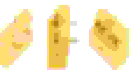
All components inside the housing with the thin bar not looking good:

Backside of the housing, the thin bar is bulging upwards, hoping it will notcause prevent the ashtray lid from closing:

side view, with the USB socket exposed:

Overview with cover in place.
The slider switch is difficult to operate. Use a pen or I have to grow some longer nails....

Using a clone Arduino Nano with an Atmega168 processor will not hold the Arduino code (too big)
Therefor an Arduino with at least the Atmega328P chip is needed. The Robotdyn Nano V3 has such a chip (Old Bootloader).

If a HC-05 is used which is fully 5V compatible, notable by the fully green PCB design in stead of blue,
and the writing "www.hc01.com" on it, the voltage divider is not necessary any more.
Hence the (final) electrical circuit design change:

The 3D print is now painted, not quit happy with the result but it'll do.
The thin bar bulges and the paint doesn't look good in that area probably due to curing it at 40�C after 24hrs drying.
Soldering is finished, and did a final test in the car.
I also soldered a loose wire with crimp connector to the Arduino pin D7, this will let me
re-program the HC-05 if it will ever break down (connecting it to the "key" pin of the HC-05).
After soldering, I fixed the cables in place with "UHU Max repair extreme" glue,
this way the fragile cables will not come loose due to movements.
For connections to the display and HC-05 I'm using these crimp connector housings,
the crimps from arduino female jumper cables fits them nicely.
I'm using a JST-XH connector, this will pass through the "ashtray illumination-hole". Just because I had them laying around.
Arduino code:
This changed also a little, and now uses 98% of internal Arduino memory (if using the correct Arduino nano, see image below)
When changing the code to imperial (fahrenheit / MPH) this drops to 97% (probably due to the "drawCircle" not taking place).
The complete revised code can be downloaded here (unzip it).
Video:
Power is not yet coming from the car, but from a powerbank, and a modified USB cable connected the the JST-XH connector.
Pictures:
Soldering overview with the (female) JST-XH connector at the bottom:
Another view:
Zoomed arduino view with the "UHU glue" visible:
The slider switch also glued:
The push button and photo-resistor also used some glue.
There are 2 resistors in there, not visible but protected by heat shrink tubing:
All components inside the housing with the thin bar not looking good:
Backside of the housing, the thin bar is bulging upwards, hoping it will not
side view, with the USB socket exposed:
Overview with cover in place.
The slider switch is difficult to operate. Use a pen or I have to grow some longer nails....
Using a clone Arduino Nano with an Atmega168 processor will not hold the Arduino code (too big)
Therefor an Arduino with at least the Atmega328P chip is needed. The Robotdyn Nano V3 has such a chip (Old Bootloader).
If a HC-05 is used which is fully 5V compatible, notable by the fully green PCB design in stead of blue,
and the writing "www.hc01.com" on it, the voltage divider is not necessary any more.
Hence the (final) electrical circuit design change:
Last edited by Cabrio Bob; 07-04-2020 at 09:01 AM. Reason: added power information
#43
07-04-2020, 08:49 AM
#44
07-04-2020, 12:45 PM
Veteran Member
This is a neat project am seriously looking to make this device too. A question, can the OBD reader be a universal unit, that is, any Android OBD one can purchase of the net?
#45
07-04-2020, 01:19 PM
OK, I thought I missed it. Could not power be picked off the lighter socket? Although, I suppose one could use a power bank to make it less complicated.
This is a neat project am seriously looking to make this device too. A question, can the OBD reader be a universal unit, that is, any Android OBD one can purchase of the net?
This is a neat project am seriously looking to make this device too. A question, can the OBD reader be a universal unit, that is, any Android OBD one can purchase of the net?
In general I think if the OBD reader works with torque, it will also work with my design. Get one that shuts down after some time the car is turned off,
then you can leave it plugged in.
#46
07-05-2020, 06:33 PM
Veteran Member
Hey Mate
Unless I missed tit, did you comment on what make and model ELM OBD reader you were binding to? I can't tell from the Vid in post 26?
This brings up a another question, I see where you mentioned a "rename" command, what command string did you use to bind the device to the reader? Thanks again.
Unless I missed tit, did you comment on what make and model ELM OBD reader you were binding to? I can't tell from the Vid in post 26?
This brings up a another question, I see where you mentioned a "rename" command, what command string did you use to bind the device to the reader? Thanks again.
#47
07-06-2020, 09:52 AM
Hello edrider,
I have this ELM327 reader (bluetooth 3.0), but in the past I had a really cheap reader and also worked fine with Torque.
Searched back in the text here but it didn't come up with the word "rename". But i Did use the command "AT+RNAME?".
Full command set I used was (in this order):
You can find the MAC address of your reader with Android apps like "Bluetooth Mac Address Finder".
p.s. I was thinking about approaching it a more professional way,
skip all the wire soldering, design a PCB, and solder everything to that (only 2 wires needed, +5V and ground).
And it will be easier for other to fabricate this. Later more about that.
Of course the current wire "mess" also works.
Today I used the current setup in my car and I am already annoyed by the refresh rate of the display,
so I might dig into this "Wemos LOLIN32" device I have. That should speed up things.
I have this ELM327 reader (bluetooth 3.0), but in the past I had a really cheap reader and also worked fine with Torque.
Searched back in the text here but it didn't come up with the word "rename". But i Did use the command "AT+RNAME?".
Full command set I used was (in this order):
- AT (should return "OK". If not you're not connected to the HC-05, or you're not in AT mode)
- AT+RESET
- AT+ORGL (Set to original)
- AT+ROLE=1 (Set to Master)
- AT+CMODE=0 (Set connect to a specific address)
- AT+BIND=DC0D,30,488D60
- AT+INIT (Need to connect)
- AT+RNAME?DC0D,30,488D60 (check if address is correct)
- AT+PAIR=DC0D,30,488D60,20 (,20 means 20 second timeout)
- AT+LINK=DC0D,30,488D60
You can find the MAC address of your reader with Android apps like "Bluetooth Mac Address Finder".
p.s. I was thinking about approaching it a more professional way,
skip all the wire soldering, design a PCB, and solder everything to that (only 2 wires needed, +5V and ground).
And it will be easier for other to fabricate this. Later more about that.
Of course the current wire "mess" also works.
Today I used the current setup in my car and I am already annoyed by the refresh rate of the display,
so I might dig into this "Wemos LOLIN32" device I have. That should speed up things.
Last edited by Cabrio Bob; 07-06-2020 at 09:55 AM.
The following users liked this post:
MarkyUK (07-06-2020)
#49
07-07-2020, 01:38 AM

I'm jumping into this discussion a little late, but I am fascinated and impressed with it as I do a lot of work with Arduinos and 3d printing. To be more specific I built an entire pinball machine that way, plus a crane machine and some other smaller projects.
I'm curious about your use of PLA in that the glass transition temperature of PLA is 140 degrees F (60 C) and it can start to deform at that temperature. I am not sure where you live but there are parts of the U.S. that can probably get the interior of a car that hot during the summer. What I am wondering is if you have put any thought into getting a spool of ABS and printing with that? It might save you some problems down the road.
If you've already addressed this I apologize as I skimmed through the thread and picked out the parts that caught my eye. I didn't see any references to 3d material aside from your test print and some pictures of the great print you ended up with and painted.
I have to admit that I wouldn't have thought about using an Arduino for this purpose, I guess I'm stuck in the mindset of an Arduino mostly reading high and low switch states. It's quite cool what you have accomplished.
EDIT: Stupid me. I see you had it printed in nylon! My apologies for skimming and for wasting time. (forehead slap)
Last edited by De5in; 07-07-2020 at 01:43 AM.
The following users liked this post:
Cabrio Bob (07-07-2020)
#50
07-07-2020, 07:56 AM
Senior Member
The following users liked this post:
Doctodd (06-03-2021)
#51
07-07-2020, 11:16 AM
It's mainly caused by not being able to edit posts after a day, resulting in scattered info all over the place in this thread (and other threads).
BTW, in my previous post I talked about ditching all the wires and create a PCB where all components are soldered onto.
At the same time switching from Arduino to an ESP32 with bluetooth, making the HC-05 module obsolete, and improve the refresh rate of the TFT display.
An ESP32 can still be programmed with Arduino IDE, and uses almost identical code.
First impression video (not yet based on ESP32) :
The following users liked this post:
RedRider48 (07-15-2020)
#54
07-07-2020, 10:58 PM
#55
07-07-2020, 11:00 PM
#56
07-13-2020, 02:19 PM
So it's been a while.
All above posts I now consider as "old", I totally switched to using an ESP32, and using a custom designed PCB.
Yesterday I worked on designing the PCB, which is as good as finished.
This evening I was struggling with the SSD1283a library, making it work with the ESP32.
What a difference this makes compared to a Nano, screen refresh without a delay due to the dual core processor,
and room for more "pages" on display due to the higher internal memory.
I placed a message on the arduino forums as a thank-you.
It's not the lolin ESP32 I was talking about before but a newly ordered small board with headers already soldered onto it.
A similar example on aliexpress: this one. This will plug in the PCB without soldering wires.
The 3D print design is also a good as finished,
video with the design:
pictures of the PCB design in Eagle:


Pinout scheme of a ESP32 "Devkit V1":

All above posts I now consider as "old", I totally switched to using an ESP32, and using a custom designed PCB.
Yesterday I worked on designing the PCB, which is as good as finished.
This evening I was struggling with the SSD1283a library, making it work with the ESP32.
What a difference this makes compared to a Nano, screen refresh without a delay due to the dual core processor,
and room for more "pages" on display due to the higher internal memory.
I placed a message on the arduino forums as a thank-you.
It's not the lolin ESP32 I was talking about before but a newly ordered small board with headers already soldered onto it.
A similar example on aliexpress: this one. This will plug in the PCB without soldering wires.
The 3D print design is also a good as finished,
video with the design:
pictures of the PCB design in Eagle:
Pinout scheme of a ESP32 "Devkit V1":
The following users liked this post:
barnsie (07-22-2020)
#57
07-22-2020, 01:28 PM
An update,
The "old" NANO-based unit is now in my car for a week or so, a few times it had connection problems to the ELM327 while driving.
This morning when driving to work it did not startup at all, only showing a white screen. Later when going home, it worked without issues again.
so not very reliable currently.
Update about the ESP32 based unit:
The 3D print design is finished, tomorrow I will order a 3D print (this time through i.materialise).
The PCB design is also finished, and I ordered 20 pieces (!) through www.jlcpcb.com. Including shipping this only costs €12.63.
Delivery time is 20 days.
ESP32-based parts list (ex shipping):
ESP32 $3.51
SLS nylon ashtray 3D print €40.59
TFT display $2.94
Tactile button 6x6x9 $1.19 (you get 100 pcs)
JST-XH 2P connector set $0.95 (you get 10 sets)
2x female header 15P $1.22 (you get 2x 5 pcs)
slide switch $0.28 (you get 10 pcs)
photo-resistor $0.78 (you get 20 pcs)
resistor set $3.67 (330Ω and 27KΩ needed)
DC/DC converter $1.21 (or you can use an UBEC (5V) or something like that)
PCB (see above and below)
optional: tactile button cap $0.82 (makes it more convenient to press the button)
Final PCB design, top (it's green but I ordered black):

Final PCB design, bottom:

The "old" NANO-based unit is now in my car for a week or so, a few times it had connection problems to the ELM327 while driving.
This morning when driving to work it did not startup at all, only showing a white screen. Later when going home, it worked without issues again.
so not very reliable currently.
Update about the ESP32 based unit:
The 3D print design is finished, tomorrow I will order a 3D print (this time through i.materialise).
The PCB design is also finished, and I ordered 20 pieces (!) through www.jlcpcb.com. Including shipping this only costs €12.63.
Delivery time is 20 days.
ESP32-based parts list (ex shipping):
ESP32 $3.51
SLS nylon ashtray 3D print €40.59
TFT display $2.94
Tactile button 6x6x9 $1.19 (you get 100 pcs)
JST-XH 2P connector set $0.95 (you get 10 sets)
2x female header 15P $1.22 (you get 2x 5 pcs)
slide switch $0.28 (you get 10 pcs)
photo-resistor $0.78 (you get 20 pcs)
resistor set $3.67 (330Ω and 27KΩ needed)
DC/DC converter $1.21 (or you can use an UBEC (5V) or something like that)
PCB (see above and below)
optional: tactile button cap $0.82 (makes it more convenient to press the button)
Final PCB design, top (it's green but I ordered black):
Final PCB design, bottom:
Last edited by Cabrio Bob; 07-22-2020 at 01:45 PM. Reason: added info
#58
08-08-2020, 12:37 PM
It's been a while, an update.
I made a mistake with the PCB design, traces from the ESP32 to the display are wrong, so I re-ordered some PCB's.
Nevertheless I test-soldered components to the PCB to see how that goes.
Also an ashtray 3D print was ordered, this time I have chosen for technique "Multi Jet Fusion" (dutch website) from Hewlett Packard.
Results are similar to SLS nylon, but it feels slippery and greasy and I'm not sure if it will hold any paint.
P.s. I might be willing to sell a limited amount of units later on when I'm happy with the results,
Exactly how I'm not sure yet, but where I'm sure of is that I'm not making money from it, and it will be without any guarantees.
More to come later.
Some pictures, colours are a bit off, due to the last 2 pictures taken (custom white balance)
"Multi Jet Fusion" 3D print (actually its grey):

Backside

PCB with components soldered (ruined display, molested push button).
The LDR (photo-resistor) will be changed from a GL5537 to a GL5528 (better sensitivity in the low light range), since it now runs on 3.3V.

Backside PCB with components soldered (ESP32 can be removed, it's attached with female headers)
The soldering looks messy, but that's due to the flux inside the solder.
The R2 27K resistor will be changed to a 8.2K, since the photo-resistor now runs on 3.3V

PCB fitment in ashtray 3D print

lid on the ashtray

Some weeks ago, special effect photography,
DIY "Full Spectrum" converted camera, with an Infrared-pass filter in front of the lens, and used a custom white-balance (and some photoshop post-processing).


I made a mistake with the PCB design, traces from the ESP32 to the display are wrong, so I re-ordered some PCB's.
Nevertheless I test-soldered components to the PCB to see how that goes.
Also an ashtray 3D print was ordered, this time I have chosen for technique "Multi Jet Fusion" (dutch website) from Hewlett Packard.
Results are similar to SLS nylon, but it feels slippery and greasy and I'm not sure if it will hold any paint.
P.s. I might be willing to sell a limited amount of units later on when I'm happy with the results,
Exactly how I'm not sure yet, but where I'm sure of is that I'm not making money from it, and it will be without any guarantees.
More to come later.
Some pictures, colours are a bit off, due to the last 2 pictures taken (custom white balance)
"Multi Jet Fusion" 3D print (actually its grey):
Backside
PCB with components soldered (ruined display, molested push button).
The LDR (photo-resistor) will be changed from a GL5537 to a GL5528 (better sensitivity in the low light range), since it now runs on 3.3V.
Backside PCB with components soldered (ESP32 can be removed, it's attached with female headers)
The soldering looks messy, but that's due to the flux inside the solder.
The R2 27K resistor will be changed to a 8.2K, since the photo-resistor now runs on 3.3V
PCB fitment in ashtray 3D print
lid on the ashtray
Some weeks ago, special effect photography,
DIY "Full Spectrum" converted camera, with an Infrared-pass filter in front of the lens, and used a custom white-balance (and some photoshop post-processing).
#59
08-08-2020, 04:15 PM

Veteran Member
Will have to be black though

The following 2 users liked this post by MarkyUK:
ArtyH55 (09-13-2020),
wicklewamb (08-23-2020)