When you click on links to various merchants on this site and make a purchase, this can result in this site earning a commission. Affiliate programs and affiliations include, but are not limited to, the eBay Partner Network.
I have the infamous C0195 code (Hydraulic pump fault, ABS & Traction warnings).
Normally the solution is to resolder connections in the ABS module. However that applies to the 4-port ABS module on the ‘97-2004 cars. For 2005-2006 they changed to an entirely different 6-port module. Mine’s an 06 XKR.
I have replaced all the wheel sensor wires (even wrote an article on that!), replaced the pedal switches, reseated the ABS connector a few times. I get the warning about 90% of the time although sometimes it will stay off for 20 minutes on cold mornings.
Any thoughts? I’ve got a couple of months until the next inspection.
It's possible that your ABS pump motor is failing, but the most likely cause of C1095 is that one or both solder connections for the connector pins for the pump motor is cracked. ATE (Alfred Teves Co.) had trouble with module solder joints for many years. While you're inside the module, it's prudent to re-flow and supplement all of the cold, cracked or starved solder joints you find on the circuit board, not just the ones for the pump connector pins. All the modules I've serviced have had several bad joints, and so far, in every case repairing the bad solder joints has been a permanent repair for C1095, going back to the 1990s.
For some reason I was thinking that all the modules had 6 valves without traction control and 9 valves with traction control, but I may be remembering incorrectly.
P.S. I changed the title of your thread to reflect the correct DTC.
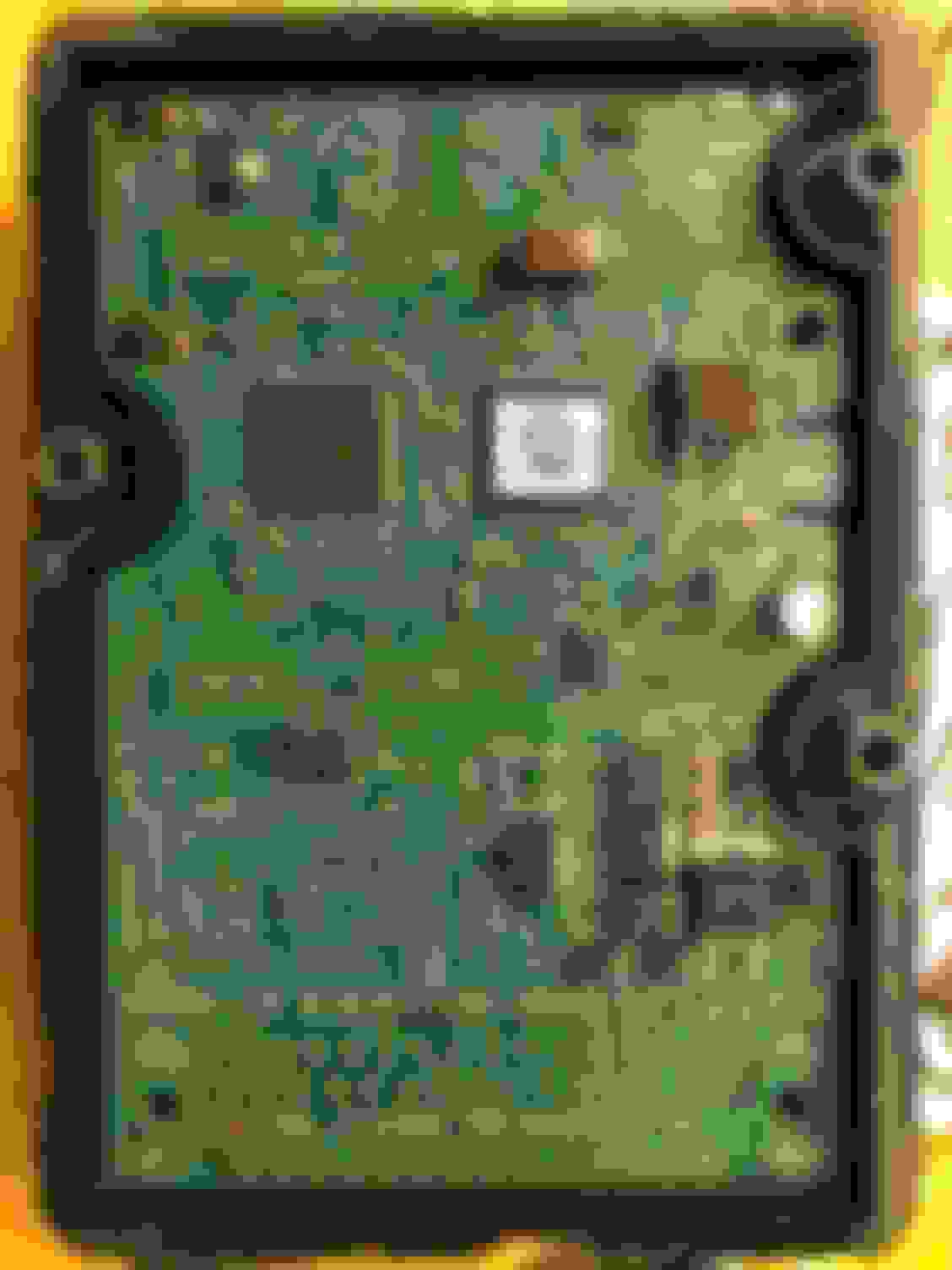
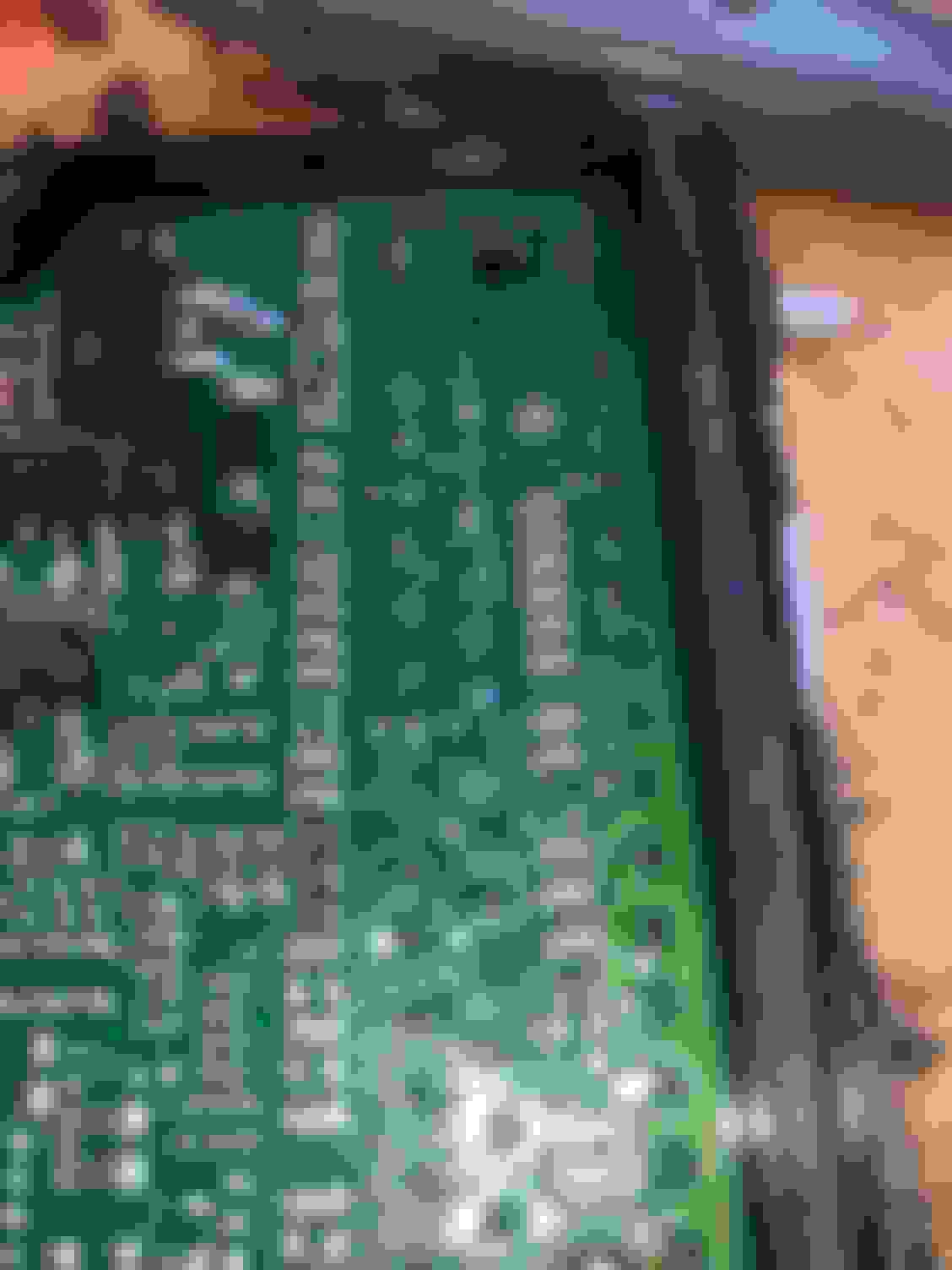
So here’s the inside of a 2005/2006 XKR ABS unit. Quite different from the earlier ones. Now, every one of the 50 or so external connectors looks like a dry joint. Are those supposed to be soldered? It looks like maybe they’re supposed to friction fit and connect to the through hole plating on the PCB? If I solder these then am I creating (or missing) some other problem on the PCB?
Those are press-fit or swage-fit pins, but I think they are supposed to be soldered after they are pressed into the circuit board, probably by wave soldering. It is unlikely you would hurt anything by soldering them, as long as you don't overheat the circuit board and cause the traces to peel up.
With Don, I cannot see, however, any harm in ensuring that they are connected by carefully soldering them (since that is the question here) rather than tracing and evaluating every pin. I would, however, make sure the power pins are connected in any case...
Thanks crbass that also answers one of my other questions which was whether I should try to lift out the board and re-seat it to try to improve the connection. I will NOT be doing that for two reasons, one is that the solderless pin manufacturer says they have a high insertion force requiring a jig to reinsert, two is that the pins have a controlled crush section which I am assuming is a one-time affair (otherwise they would have described it as a spring section).
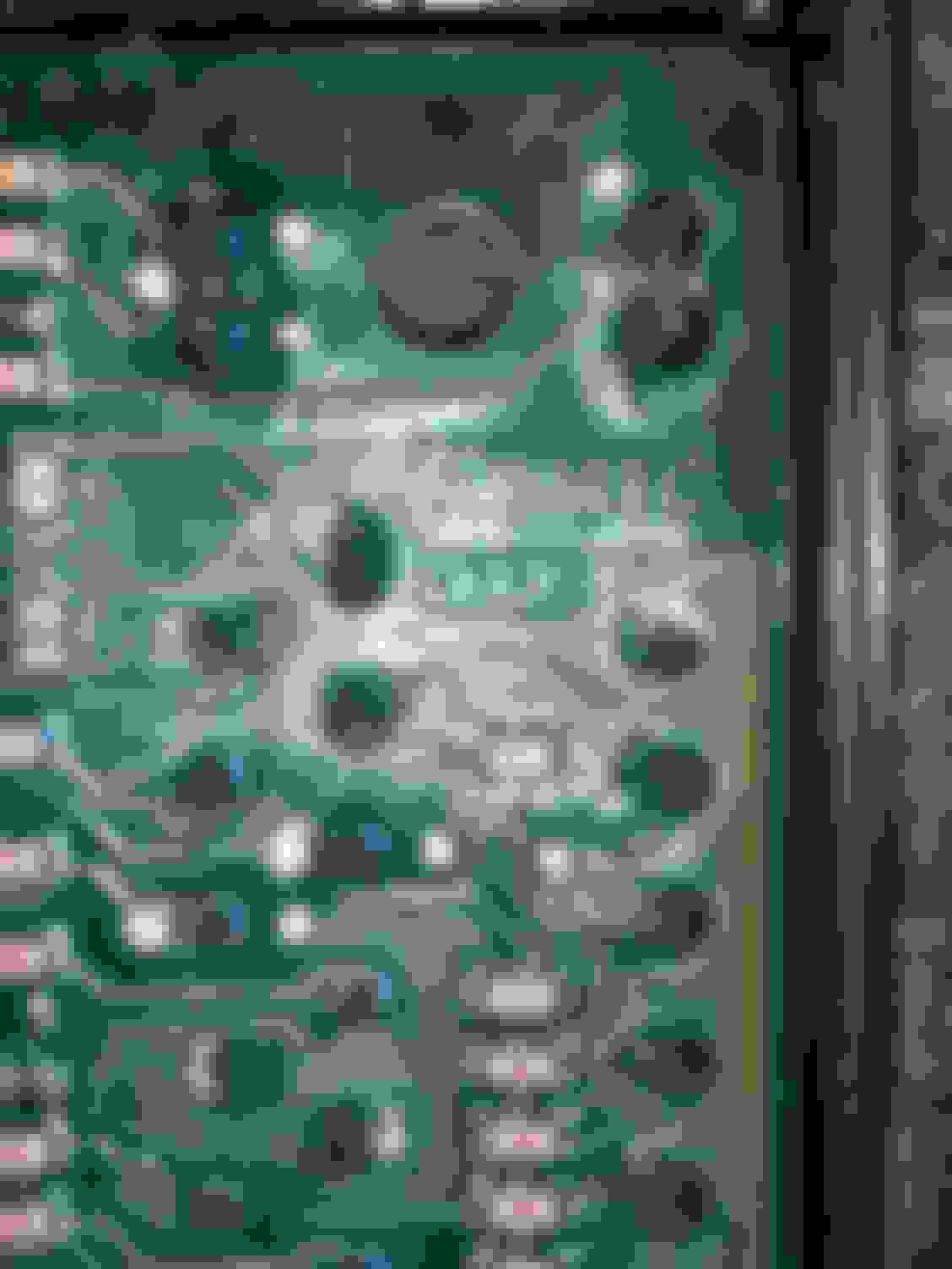
Upon closer inspection some of the solder joints on the power transistors look dodgy, there’s black oxidation on them for sure, I can’t tell if they’re cracked though. I have ordered a magnifying headband and then I will be getting very personal on this unit with the soldering iron...
In all honesty I was a bit skeptical, the Teves Mark IV unit in the ‘98-‘2003 (ish) has many reports of that solder joint reliability problem, but the Teves Mk25 unit in the 2005-2006 cars doesn’t even have the same solder joint that fails in the earlier units.
So on my 2006 mk25 unit I soldered all of the header pins for the connector and especially the ones for the ABS pump. Used soldering iron at 420 degrees F. I had to change out the soldering iron bit from a pointed one to a flat edge one to get enough heat into the PCB track that it would melt the solder. Flat edge against the PCB and the pin up against the shaft of the bit and solder applied to the PCB right where it meets the pin. Used Kestler high flux (3.3%) eutectic silver-bearing lead/tin solder.
There are four sets of 4 solder joints to some components under the board I couldn’t see, I didn’t see any signs of cracking but two of them had solder bridges (how did that pass inspection?!?) which I removed with solder braid. Then resoldered all of them.
I mentioned one of the legs of one power transistor looked suspect, upon closer inspection it didn’t look that bad. I tried to resolder it but there was too much heat-sinking going on and decided that discretion was the better part of valor, so just added some solder to that joint and reflowed it and then left the remainder of the power transistors connections alone.
Since I had to open all of the brake line flare connections on top of the ABS unit to get the ECM in and out, of course I finished with the obligatory 4-wheel brake flush.
AD2014 (02-01-2021),crbass (01-31-2021),Don B (01-31-2021),Jon89 (02-01-2021),michaelh (02-01-2021),RJ237 (01-31-2021) and 1 others liked this post. (Show less...)
I'm not the least bit surprised though. Reflowing and supplementing the solder joints on those modules has worked on every one I've tried so far regardless of vintage.
Big thanks to Don and Crbass, without their encouragement and info I wouldn’t have done it. Thank you so much, I owe you beers should we ever meet, and may good karma take care of you if we don’t.
I hope my documentation helps the next person, let’s all keep these beauties on the road as long as we can.
Couple things I forgot to add in my write up:
Read instructions for the repair on the earlier units to know what you’re in for. Before final reassembly, clean the spade connector pins on the little black tower that connect the ABS module to the ABS pump; mine were quite oxidized and needed a light sanding with extrafine sandpaper. Also clean excess solder flux from the PCB with isopropyl alcohol before reassembling the unit with red rtv gasket maker.
Another unintended consequence of the RoHS directive, although - from the notes in Dale's link - "...and significant reduction of production costs" of the use of these devices may be a contributory factor

 01-18-2021, 11:25 AM