
CATS with a switch
#21
 05-24-2012, 07:24 PM

I'm not entirely sure of the physical locations for an XJ and I don't have the JTIS in front of me to look. In the XK the lateral one is the one in front on the right side near the ECU and those are the pins & wire colors I am referring to.
The lateral sensor has a nominal output of 1.5V so superimposing a 2.5V signal is enough to convince the system you are going around a corner. If the easily accessible sensor is one of the vertical ones then the nominal output is 2.5V so you will need to change the resistors to get something higher. A 2/3 or 3/4 divider might work but I'm not sure how much is needed.
What I do know is that putting a strait 5V on the vertical signal doesn't work but I didn't try to confirm whether the reason was the voltage being too high or because there are two vertical sensors and the system is comparing the two.
#22
06-02-2012, 10:25 AM
So, I finally built up the circuit in a permanent way and tied it into the sport switch. Just need to run 1 signal wire from the switch to the circuit, all the rest fits nicely next to the CATS control in the boot. A little double stick tape to insulate the back side of the board also serves to attach it to the control box.
The Sport switch put +8V when "off" and ties to ground when "on". The circuit is a voltage divider between the +5 and GND pins for the accelerometer sensors and the transistor acts as a switch such that it's open when the +V is applied from the sport switch and closes when tied to ground.
All built up the sensor line has +1.6V when sitting still and +2.2V when Sport is turned on.
If I ever get a copy of AutoEnginuity I could know for sure that it's toggling the mode but by the seat of the pants feel of it, I would say that it works.
Even if the voltage needed to be a little higher, it would just be a matter of changing the resistor values a little. The principle seems to be sound.
Has been a fun little experiment so I'll toss it out there in case anyone else is interested.
The following users liked this post:
WhiteXKR (06-03-2012)
#23
06-03-2012, 08:20 AM
Veteran Member
#24
06-09-2012, 02:18 PM
This little feature worked fine over the last few weeks slogging around town but I got out on some mountain twistys today and got a suspension fault. Turning off Sport mode cleared the fault so no permanent harm done.
Looks like in tossing her through the corners the system got wise to my little trick of fudging the accelerometer input.
Haven't given up though, there are still a few other things to try.
Looks like in tossing her through the corners the system got wise to my little trick of fudging the accelerometer input.
Haven't given up though, there are still a few other things to try.
#25
06-09-2012, 02:33 PM
Veteran Member

#27
06-09-2012, 05:53 PM

I've always wondered (JTIS just sometimes doesn't provide enough detail) is CATS all or nothing, meaning that all shocks are firm or all shocks are soft.
Or is it a little smarter where it would do something like:
-on a turn stiffen the inside two while keeping the outside two soft.
-while accelerating, keeping the rear two firm and front two soft.
-while braking, keeping the front two firm and rear two soft.
or something like this.
This is why I assumed it never had a firm / soft switch, but then maybe it's just because of Jaguar wanting most things automatic in their luxury coupe.
The following users liked this post:
User 070620 (07-24-2012)
#28
06-09-2012, 10:30 PM
I read the first paragraph of the Operations section of JTIS to mean that it's all or nothing.
I haven't actually monitored the driver lines to the shocks themselves so I can't confirm this directly. With access to WDS or AutoEnginuity then you could likely monitor the system status real time and see what it was doing.
The firm setting is definitely off (no voltage applied) which is true when sitting still and this is also what happens when you disconnect a shock or when there is a system fault.
The control communicates a fault back to the instrument cluster by grounding the signal wire. Letting it float indicates all clear, which is consistent with those that have unplugged the control entirely to run without CATS shocks.
My thought was that it might work to simply disconnect the power to the controller as a way to force the firm setting. The easiest test will be to pull either the +12 or ignition pin to see if firm is set and if any fault occurs.
The four adaptive damping units are simultaneously switched to either firm or soft setting to suit circumstances. When the vehicle is stationary, the system adopts the firm setting to minimize vehicle pitch during initial acceleration. From 8km/h (5mph) upwards, the system reverts to the soft setting until otherwise switched by the ADCM.
The firm setting is definitely off (no voltage applied) which is true when sitting still and this is also what happens when you disconnect a shock or when there is a system fault.
The control communicates a fault back to the instrument cluster by grounding the signal wire. Letting it float indicates all clear, which is consistent with those that have unplugged the control entirely to run without CATS shocks.
My thought was that it might work to simply disconnect the power to the controller as a way to force the firm setting. The easiest test will be to pull either the +12 or ignition pin to see if firm is set and if any fault occurs.
#29
07-22-2012, 01:54 PM
Senior Member
Thanks WhiteXKR for the info file. Now I know what's going on with the CATS system. I am thinking that the faster you go the firmer the dampening will get. I was traveling around 75 MPH on a concrete super highway and could feel some road variations in the steering wheel. I got a little concerned about the feel. I think that if one of the front shock is leaking it will cause a more dampened ride and give this feeling of the road on that side. I plan to get both replaced in a few weeks. I believe that is the rule of thumb with shocks even though the other side is OK?? The back shocks both look OK for now.
Bill N
Bill N
#30
07-23-2012, 05:19 AM
Veteran Member
My guess is the module is seeing pitch signals from the vertical accelerometers large enough to trigger CATS to hard, then these go away but your fake lateral one doesn't.
Why not spoof the speed input ?
The four adaptive damping units are simultaneously switched to either firm or soft setting to suit circumstances.
When the vehicle is stationary, the system adopts the firm setting to minimize vehicle pitch during initial
acceleration. From 8km/h (5mph) upwards, the system reverts to the soft setting until otherwise switched by the
ADCM.
If the ADCM thinks the vehicle is stationary it probably won't do any other checking.
Easy to measure the volts (probably zero) on pin 24 at rest, disconnect the real speed input and apply the required spoof volts.
#31
07-23-2012, 08:48 AM
Honestly, I had assumed (for no valid reason) that the speed input was a pulse signal as from a hall sensor or something like that but it could well be a proportional voltage.
I either case, perhaps it would be as simple as disconnecting the signal.
My other thought was to toggle the ignition signal.
#32
07-23-2012, 08:53 AM
Veteran Member
It would be no big deal to disconnect the ignition but, knowing the low-down cunning of the car the ADCM probably has to tell the ECU that it's feeling good or the ECU will spit out its dummy.
I thought, since the other inputs are analogue, it was probably volts but even if it's pulses I reckon 0 mph = 0 pulses (but it is a jaguar)
I thought, since the other inputs are analogue, it was probably volts but even if it's pulses I reckon 0 mph = 0 pulses (but it is a jaguar)
#33
11-17-2012, 09:12 AM
I finally got back to this little project and am pretty sure it is working properly this time.
It turns out CATS is a stand alone system and unlike many of the other modules, it only communicates with the rest of the car when it is 1) turned on and 2) when there is a problem, so if the controller is turned off them there is no communication and no error messages.
I'm using the term communication liberally here, as the only real connection between CATS and the outside world is a single line that runs to the instrument cluster. When the controller pulls that to ground the cluster shows the SUSPENSION FAULT message but so long as the controller is off or unplugged there will never be a fault message, no matter what else happens. This simplicity is why unplugging the controller lets someone use non CATS shocks without a problem.
It also happens that the "system off " mode is the FIRM setting, which is something that we can take advantage of. I tied it to the sport switch such that:
Sport off -> CATS on -> suspension soft
Sport on -> CATS off -> suspension firm
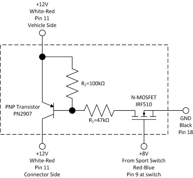
Here is what I wired up and how it's connected:

I am not generally a fan of cutting wires but if you want to try this save yourself a lot headache and just cut the wire going to pin11 and tie in the circuit. I tried to extract the pin so I could remake the harness without cutting anything but I spent HOURS fiddling with it, eventually broke the wire, resorted to pliers and then when the pin did finally come out of the connector it was in 3 pieces. I was able to get a replacement pin and put it back together but by that point I was fed up and just spliced the thing.
The currents in this circuit are tiny, so the transistor and resistor choices are not especially important. The largest current is on the +12 ignition wire to turn the controller on and off, which carries about 6mA, so not very much at all. The components I used are what the local Radio Shack had in stock (which isn't much these days).
When toggling the sport switch there is an audible click in the controller when it switches on and off. The suspension can be toggled any time while driving without problems and there is a subtle but noticeable change in the ride.
For now, it's still in breadboard form in the boot, but I'll solder it up to make it smaller and more permanent.
It turns out CATS is a stand alone system and unlike many of the other modules, it only communicates with the rest of the car when it is 1) turned on and 2) when there is a problem, so if the controller is turned off them there is no communication and no error messages.
I'm using the term communication liberally here, as the only real connection between CATS and the outside world is a single line that runs to the instrument cluster. When the controller pulls that to ground the cluster shows the SUSPENSION FAULT message but so long as the controller is off or unplugged there will never be a fault message, no matter what else happens. This simplicity is why unplugging the controller lets someone use non CATS shocks without a problem.
It also happens that the "system off " mode is the FIRM setting, which is something that we can take advantage of. I tied it to the sport switch such that:
Sport off -> CATS on -> suspension soft
Sport on -> CATS off -> suspension firm
Here is what I wired up and how it's connected:
I am not generally a fan of cutting wires but if you want to try this save yourself a lot headache and just cut the wire going to pin11 and tie in the circuit. I tried to extract the pin so I could remake the harness without cutting anything but I spent HOURS fiddling with it, eventually broke the wire, resorted to pliers and then when the pin did finally come out of the connector it was in 3 pieces. I was able to get a replacement pin and put it back together but by that point I was fed up and just spliced the thing.
The currents in this circuit are tiny, so the transistor and resistor choices are not especially important. The largest current is on the +12 ignition wire to turn the controller on and off, which carries about 6mA, so not very much at all. The components I used are what the local Radio Shack had in stock (which isn't much these days).
When toggling the sport switch there is an audible click in the controller when it switches on and off. The suspension can be toggled any time while driving without problems and there is a subtle but noticeable change in the ride.
For now, it's still in breadboard form in the boot, but I'll solder it up to make it smaller and more permanent.
The following 8 users liked this post by ccfulton:
Aonsaithya (08-26-2018),
Bad Cattitude (07-14-2013),
BadenXJR (04-22-2017),
MarcB (01-18-2013),
rocklandjag (11-18-2012),
and 3 others liked this post.
#35
11-17-2012, 08:37 PM
I'm not really sure what that transistor in the switch is for, unless the original design intent was something similar to what I am trying to do with this add on circuit.
#36
11-18-2012, 07:11 AM
Senior Member
Pin 2 was connected to the transmission control module on earlier models.
As long as Jaguar didn't see a chance to save money and leave the transistor out of the 4.2 version of the switch!
#37
11-18-2012, 08:09 AM
Veteran Member
Just as an aside, here is a bit of insight into the electronics in these cars (and often the reason behind transistors in strange places) from a paper given by Jaguar in 1996 at the UK IEE on the electronic design approach in the XK8:
All modules were designed to ensure that all signals have an active threshold of 10 mA. This greatly increases the resistance to EMC, electrical disturbance and leakage currents arising with age of the vehicle. Sensitivity analysis was used to consider what impact the wiring, connectors and switch gear may have on the Active and In-Active margins of each modules input circuitry, considering: ageing, wear, Battery voltage, Ambient temperature, tolerance, component interaction on fuse and ground networks, etc.
All modules were designed to ensure that all signals have an active threshold of 10 mA. This greatly increases the resistance to EMC, electrical disturbance and leakage currents arising with age of the vehicle. Sensitivity analysis was used to consider what impact the wiring, connectors and switch gear may have on the Active and In-Active margins of each modules input circuitry, considering: ageing, wear, Battery voltage, Ambient temperature, tolerance, component interaction on fuse and ground networks, etc.
Emphasis has then been placed on signals/signal types that do not comply with the minimum current rule requirement, allowing greater attention to be given to those circuits, e.g. twisted pair, shielding, cross coupling, filtering, special attention to terminal plating and connector application, etc.
Last edited by WhiteXKR; 11-18-2012 at 08:11 AM.
#38
11-18-2012, 04:50 PM
Senior Member
#39
03-07-2013, 08:00 PM

I just did similar to this on my XK8 using the old 'analog' method of relay and a switch. The ADC ontrol unit is missing from my car ( removed by P/O for some reason ) so I wired direclty to the multi-pin connector on the wriring harness using small crimp pins which fit snugly into each terminal / recepticle.
I picked up the 5A ignition feed through a switch to operate a relay which switches the 20A feed directly to all 4 corners. I'm going to run it like this for a while, I have purchased a 2nd hand control unit to try which may or may not work, depending upon whether the accelerometers are functional or not. The shocks certainly switch from hard to soft though using this hard-wired method. The good old KISS principal always works.
I picked up the 5A ignition feed through a switch to operate a relay which switches the 20A feed directly to all 4 corners. I'm going to run it like this for a while, I have purchased a 2nd hand control unit to try which may or may not work, depending upon whether the accelerometers are functional or not. The shocks certainly switch from hard to soft though using this hard-wired method. The good old KISS principal always works.