When you click on links to various merchants on this site and make a purchase, this can result in this site earning a commission. Affiliate programs and affiliations include, but are not limited to, the eBay Partner Network.
Convertible window/mirror control switch problem: [Fixed]
The window control is working fine. However, the side mirror control has some glitches.
For example, the left/right is working but up/down is not. The folding function is intermittently working, etc.
I searched and read the previous posts and decided to disassemble the switch unit to take a look.
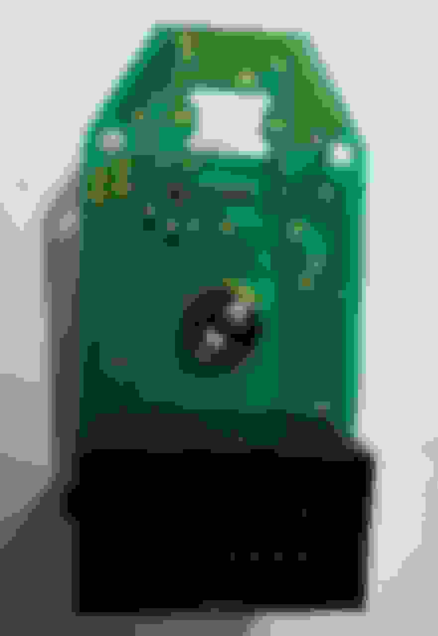
I found corrosions everywhere and cleaned it up thoroughly. I didn't see any burn marks (I could be wrong) on the board. But the symptoms are still there.
What else should I try before ordering a new switch unit?
Thanks in advance.
Last edited by szhilian39; 12-19-2021 at 01:26 PM.
Made me smile. I just went through this. Where did I start?
Do you need a pin out? (Which pin does what under what conditions?) Hell, I planned to post that anyway - lord knows I found that posting that kind of thing helps me as much as anyone else. 3, 4 years from now when I need it again - its right here. Your answer will help me prioritize it.
Circuit board status. . . You've maybe got an issue or two. Great photo BTW. See the O shaped conductive copper conductors on the board? Look at the one upper right nearest the U Shaped indented edge on the board. See how its brownish discolored? This is a sign of interrupted conductivity. Grab your ohm meter set to continuity or resistance at least. Trace that/those areas along its path. Don't forget each of those O areas is a front to back of board connector, 80% of which connect to traces on both sides.
I found that this brown tinge translated into open circuit in many cases.
How do I fix this? Well in a perfect world you could just scrape the green top layer off the traces next to the corrosion, bearing the shiny copper trace. Solder Flux applied with the pointy end of a toothpick + soldering iron with narrow pointy tip + tiny but of solder = nice flow covering the defect + the exposed trace AND NOTHING else. Ttytt I found that scraping away the top layer, and only the top layer is harder than it sounds given the width of some of these traces.
Where its just the corroded O area, I cut a piece of single strand hook up wire to the width of the circuit board. ☆☆☆don't let it protrude above the face of the board under any of the pads of the carbon embedded in the gray flexible board cover you've got from the switch disassembly☆☆☆
How do I then cut the wire to length? Well I got lucky: (1) I had hook up wire of the perfect guage at my workbench. If you need help determining the guage. Ask me. (2) I have a Leatherman brand pocket knife that comes with pliers. If this brand wasn't so common with DIY ers I wouldn't mention it. Heres the deal: look at the tips of the pliers - they are square. Good news is, the length of the "square's" edges are exactly the size of the circuit boards thickness! I used that to determine: (1) where to chop off the length of the holes i fixed like I described above, (2) where to bend the wire strand for the lengths of wire i had to use to mirror the original traces when corrosion was too extensive, or the traces were too thin for a simple solder over it.
Note: have some desoldering wick available for screw ups! Those traces are close to each other!
Of course you use even thinner wire, soldered to the back of the board to mirror the traces.
Ok now you are good to go conductivity wise, time to reassemble the board! Let me save you hours of agony :-)
Grab the jar of Vaseline or at least a can of grease.
BTW - Are you sure the light bulb is good? Nows the time to replace.
Put the circuit board on the back piece. The square shaped molds on the back piece are your ONLY hope of assembling the switch with the directional black plastic piece and the side selector U shaped plastic piece in place AND in proper orientation.
Now put the flexible grey selector switches on top.
Take a dab of Vaseline, place one on top of each pad left right up down. Place black director selector mechanism in place (see how the square protrusion fits into the back?)
Vaseline dab on the left right selector plastic. It too fits into the mold in the back.
Now ready for final assembly. The remaining piece is the plastic housing. DO THIS ABOVE A PAIL or your wife's lasagna dish - last thing you need is to loose the black plastic pins under the window switches. Friend mine didn't fall out for this, but maybe secure them with the Vaseline? Oh! Just remembered- the 2 brass pins each under left right switch and direction switch in this housing gets greased in place. You don't want to lose them!
This, the housing, gets inverted (IOW front facing up) and placed onto the back assembly. For me the brass pins line up with their respective receptacles on the 2 black plastic switches. I found that leading with the rear of the back works best.
BE SURE all tabs have clicked in place! Its easy to miss one and nothing works (guess how I know).
Friend may I ask your assistance back? As you can see from the raised switch pads on the grey flexible piece, the orientation of the left right selector is not self evident. Looking down from above, the U shaped side selector is oriented like U, not an inverted U right? I reassembled mine that way, it works, but its been nagging at me: why the hell would they have a raised switching spot on both the grey flexible piece and a defined switch spot on the circuit board below? If you didn't take photos or don't recall, orient it as a U. Thanks!
Folks, after I wrote this I relooked at his photo. There is no circuit board spot for the inverted U! Turns out there are at least 3 different versions of this darn circuit board! I've got 2 of them his is the 3rd. Dont worry its just the trace mapping, no switch or pin out differences.
Finger pointing to mysterious orphaned switch pad. FWIW one of the 3 circuit boards mentioned has a defined switch pad space under these 2 raised molds! That's what prompted my question.
Made me smile. I just went through this. Where did I start?
Do you need a pin out? (Which pin does what under what conditions?) Hell, I planned to post that anyway - lord knows I found that posting that kind of thing helps me as much as anyone else. 3, 4 years from now when I need it again - its right here. Your answer will help me prioritize it.
Circuit board status. . . You've maybe got an issue or two. Great photo BTW. See the O shaped conductive copper conductors on the board? Look at the one upper right nearest the U Shaped indented edge on the board. See how its brownish discolored? This is a sign of interrupted conductivity. Grab your ohm meter set to continuity or resistance at least. Trace that/those areas along its path. Don't forget each of those O areas is a front to back of board connector, 80% of which connect to traces on both sides.
I found that this brown tinge translated into open circuit in many cases.
How do I fix this? Well in a perfect world you could just scrape the green top layer off the traces next to the corrosion, bearing the shiny copper trace. Solder Flux applied with the pointy end of a toothpick + soldering iron with narrow pointy tip + tiny but of solder = nice flow covering the defect + the exposed trace AND NOTHING else. Ttytt I found that scraping away the top layer, and only the top layer is harder than it sounds given the width of some of these traces.
Where its just the corroded O area, I cut a piece of single strand hook up wire to the width of the circuit board. ☆☆☆don't let it protrude above the face of the board under any of the pads of the carbon embedded in the gray flexible board cover you've got from the switch disassembly☆☆☆
How do I then cut the wire to length? Well I got lucky: (1) I had hook up wire of the perfect guage at my workbench. If you need help determining the guage. Ask me. (2) I have a Leatherman brand pocket knife that comes with pliers. If this brand wasn't so common with DIY ers I wouldn't mention it. Heres the deal: look at the tips of the pliers - they are square. Good news is, the length of the "square's" edges are exactly the size of the circuit boards thickness! I used that to determine: (1) where to chop off the length of the holes i fixed like I described above, (2) where to bend the wire strand for the lengths of wire i had to use to mirror the original traces when corrosion was too extensive, or the traces were too thin for a simple solder over it.
Note: have some desoldering wick available for screw ups! Those traces are close to each other!
Of course you use even thinner wire, soldered to the back of the board to mirror the traces.
Ok now you are good to go conductivity wise, time to reassemble the board! Let me save you hours of agony :-)
Grab the jar of Vaseline or at least a can of grease.
BTW - Are you sure the light bulb is good? Nows the time to replace.
Put the circuit board on the back piece. The square shaped molds on the back piece are your ONLY hope of assembling the switch with the directional black plastic piece and the side selector U shaped plastic piece in place AND in proper orientation.
Now put the flexible grey selector switches on top.
Take a dab of Vaseline, place one on top of each pad left right up down. Place black director selector mechanism in place (see how the square protrusion fits into the back?)
Vaseline dab on the left right selector plastic. It too fits into the mold in the back.
Now ready for final assembly. The remaining piece is the plastic housing. DO THIS ABOVE A PAIL or your wife's lasagna dish - last thing you need is to loose the black plastic pins under the window switches. Friend mine didn't fall out for this, but maybe secure them with the Vaseline? Oh! Just remembered- the 2 brass pins each under left right switch and direction switch in this housing gets greased in place. You don't want to lose them!
This, the housing, gets inverted (IOW front facing up) and placed onto the back assembly. For me the brass pins line up with their respective receptacles on the 2 black plastic switches. I found that leading with the rear of the back works best.
BE SURE all tabs have clicked in place! Its easy to miss one and nothing works (guess how I know).
Friend may I ask your assistance back? As you can see from the raised switch pads on the grey flexible piece, the orientation of the left right selector is not self evident. Looking down from above, the U shaped side selector is oriented like U, not an inverted U right? I reassembled mine that way, it works, but its been nagging at me: why the hell would they have a raised switching spot on both the grey flexible piece and a defined switch spot on the circuit board below? If you didn't take photos or don't recall, orient it as a U. Thanks!
Folks, after I wrote this I relooked at his photo. There is no circuit board spot for the inverted U! Turns out there are at least 3 different versions of this darn circuit board! I've got 2 of them his is the 3rd. Dont worry its just the trace mapping, no switch or pin out differences.
John
Hi John, Wow, it's really informative. The problem is I'm not an EE guy and trying to understand your English. Can you please post a couple of pics of your work?
I am going to take out the switch unit again. Many thanks!
Never mind. I found 3 contacts at the bottom that are damaged (using a multimeter). I will update my progress. Many thanks!
Last edited by szhilian39; 12-19-2021 at 10:06 AM.
Reason: Found the solution
Thanks to Johnken, I was able to identify the bad contacts (using a digital multi meter, connectivity test).
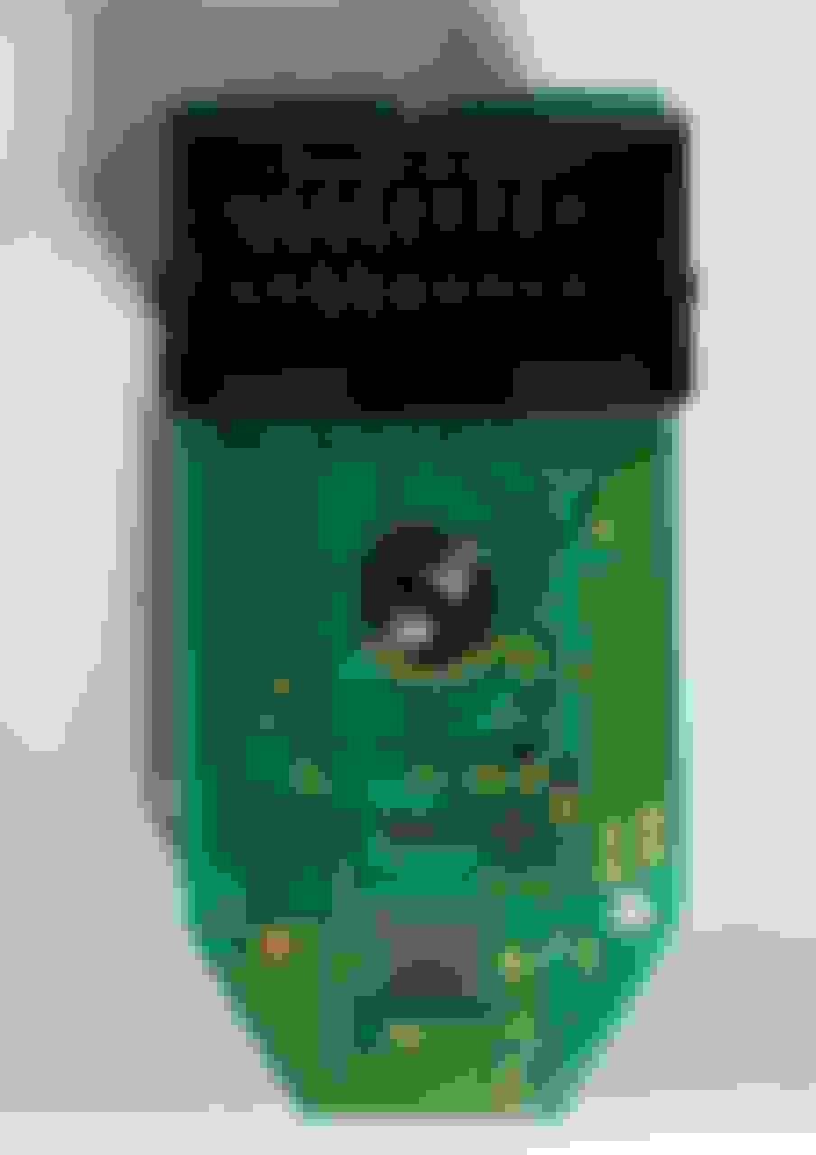
There are 3 contacts (at the bottom) that do not produce a beeping sound during the connectivity tests.
I was afraid of doing soldering on these tiny spots so I used a liquid conductive solution instead. This is from a defroster repair kit that I purchased a long time ago.
I applied a bit of solution to each spots and let it dry.
and then did a connectivity test again.... all PASSED!
After installing it back, the result is wonderful! Now, I can fold/unfold the side mirror and the position control is perfect!
I would like to thank Johnken for his useful information.
JW
Thanks to Johnken, I was able to identify the bad contacts (using a digital multi meter, connectivity test).
There are 3 contacts (at the bottom) that do not produce a beeping sound during the connectivity tests.
I was afraid of doing soldering on these tiny spots so I used a liquid conductive solution instead. This is from a defroster repair kit that I purchased a long time ago.
I applied a bit of solution to each spots and let it dry.
and then did a connectivity test again.... all PASSED!
After installing it back, the result is wonderful! Now, I can fold/unfold the side mirror and the position control is perfect!
I would like to thank Johnken for his useful information.
JW
Brilliant! And great idea! I never heard of this stuff!!!
I'm all over it! Lol. Thanks Man!
Here is what I used. It's called "Quick Grid", which was originally included in a defroster repair kit by Permatex. The kit is available at Autozone or Amazon, etc.
I believe any repair kit will do the job.
Thanks!
Last edited by szhilian39; 12-20-2021 at 08:02 PM.
 12-18-2021, 05:59 PM