When you click on links to various merchants on this site and make a purchase, this can result in this site earning a commission. Affiliate programs and affiliations include, but are not limited to, the eBay Partner Network.
Yikes, the perils of international time zones . . . so many posts while I slept and poor Bob toiled away. Now that I guess you fellas are asleep, I can catch up. We certainly appear to have strayed from what should be a clear path. It's nice of Bob to refer to us all as "young" blokes but truth is, unless you are pushing towards 80, I thank you for your (misplaced) compliment.
Back to the topic, I suspect that I can offer some clear air . . . and thanks to Bob himself who posted this at #25. Take a bow "lad" while we take a fresh look at the diagram in light of disconnecting the ignition switch but finding the fault(s) remain. Our conclusions? . . . of only 2 options, faulty ignition switch is ruled out . . . it is, as predicted, a fault generated by a wiring short from a "ground seeking" conductor to ground.
Originally Posted by Robert Grisar
From electrical guide, wiring of ignition switch and wire colors.
Having removed the ignition switch connector and B+ battery post cable (and reconnected everything else) we have isolated all this plugs & sockets discussion into 2 immutable facts . . . (1) there are 3, and only 3, earth seeking branches associated with the system, and (2) with ignition switch disconnected, each ground seeking branch is quite separate and NOT inter-connected. Here, the associated switching diagrams at top left of schematic are vital -
we can ignore the entire lower branch (for the moment) in the main diagram because it exclusively feeds our accessories and there is no way I am aware of that this branch can feed directly any IGN ON lights in the IC;
similarly, we can ignore the entire upper branch (for the moment) because it is exclusively concerned with cranking the engine at the expense of locking out our accessories;
focus on the middle branch and what do we find? Bingo, the Inertia Switch, and all other IGN related circuits, as confirmed by the switching diagrams referred to previously.
Next step? With ignition switch still disconnected, reconnect battery and use DVM (set to DCV) to test all 3 branches. I take care to avoid words like "always" or "never" but I do predict that the top branch (cranking) and bottom branch (accessories) may well show +12V (normal) but equally, I predict that the middle branch will show 0V . . . ie shorted to ground.
Final step? Move up each circuit of this IGN branch, unplugging connectors and testing with DVM until you find B+ rather than 0V (ground). Having done so, the fault is a short somewhere between this and the immediately previous connector.
Bob, please don't think I am either rebuking others' advice, nor unmindful of your patient efforts, but IMHO, you are NOT in the thrall of the Dark Side . . . I believe you are on the edge of resolution.
Good morning Truck Graphics of Maryland and my other learned friends who are trying to help me.
This morning I spent considerable time under the dash looking for the FCS20 (ign-1 accessory) and FCS26 (ing-2 on) spices. No joy.
OK. Connected battery. Got out my test light. First, tried all connections in the passenger's side fuse box located adjacent with 7 brown relays. All appear ok.
Then went into the trunk. Found two items of concern. First, simple, a blown 5A fuse that controls rear window lift motors. Easy to replace. Then looking around, I find a unconnected connector, 2-wire, to right of battery. Photo attached.
Burnt connector (melted) from right side of battery. Not connected to anything, as far as I can determine. Two wires. Disconnected battery. Cut wires, taped over. Wires are Brown-Red (or Brown-Orange) and Brown-White (or Brown-Yellow). Really suspect.
---
Before I re-connect battery, does anyone know what this is? All I can confirm from my electrical guide is that it is a Econoseal III HC, High current sealed connector.
Also, the ground strap that connects to battery (-) shows signs of a burn. Maybe some material missing, but most (90%) of strap still there. I'm guessing that there was a short, and the strap fried until something else melted or sacrificed. Anyone have thoughts here?
To truck graphics, I'll try to validate what you suggest later today.
Yesterday, MichaelH from Jersey, Channel Islands, suggested the blue connector emanating from the ignition switch area were the key exciter ring connector, which matches a page in his jtis.
To my new friend Ken from Australia. Thank you for the expiation. Since I'm in my mid70s. I can usually refer to others as younger. Nice to need someone from my generation ... There are fewer of us left every day.
Up up until now, I've been disconnecting the negative battery post. Your reply says remove positive post. Does this matter? Can I use a 12v trouble light instead of a day? For those who are following and viewed my burnt connector, here is the charred neg post cable picture
That looks like the auxiliary power connection, it needs a relay in position R6 in the trunk fuse box to operate, this is normally not installed, do you have one there? If so try pulling it out.
It is powered from fuse #17 in the drivers side fuse box so you could also pull that.
Norri, the wire colours on the burnt connector tally with the transit isolation device? I think Bob has cut it off anyway. Odd how it's got burnt, but not needed.
The battery ground strap has been getting too hot by the zip tie, most likely with the heavy load during cranking. It may have been weakened over the years by flexing and should be replaced.
Bob,
Finding these things buried in the dash can be a pain, but Ken's detailed description of how to proceed is on the money, and I agree that you're likely to find that the short is somewhere in the white/blue circuit. Look closely at that white/blue wire on its travels from the ignition switch connector as it's close to moving parts.
You would be much better armed with a DVM rather than relying on a test lamp, which might give misleading results. You're also likely to need to make some resistance checks to finally nail the problem.
One thought: unplugging the inertia switch in the LH fascia fusebox will disconnect several of the suspect connections in one go - (7 to 11) and could be a quick 'divide and conquer' approach. It looks possible to get to it without major surgery (sorry, I can't get to mine at the moment). See this picture posted by Gus: https://www.jaguarforums.com/forum/x...63/#post283793
Hello everyone. Welcome to the search Norri of Phoenix.
Everyone has given me a plan of action for the morning. Thanks to Lorri and MichaelH of Jersey, Channel Islands, for confirming the function of that the burnt connector in the trunk. Surprisingly, there was no relay in position R6 in the trunk fuse box. Clearly a leftover from some other failed attempt.
Thanks to MichaelH for his suggestion on the inertia switch (and pointer to Gus' picture) in the Drivers LH fascia fuse box. That will reduce a lot of hunt and peck.
Sorry about my thoughts using the trouble light when power is on. Yes, of course the DVM is the way to go for voltage, and with power off, the resistance. I once had a very bad experience, different car, with using the meter with power on. Lots of sparks and blown fuses.
And, to my contemporary Ken in Australia, thank you for a plan of action. I really needed a guide, and your explanation hit the spot.
Encouraged in Florida (where it was 75F today), Bob G.
Greetings Bob, Michael, Norri et al . . . and thanks to all for your patience with my time-zoned absences. Bob, you are in fine hands with Michael's analysis (mice notwithstanding ) -
+1; to isolate battery, matters not which battery post you disconnect, but I agree that NEG strap needs replacing;
+1; with battery reconnected, if that ground seeking branch from inertia switch (WU) is already grounded as predicted, then isolate inertia switch and retest both "upstream" branches of inertia switch (GU) & (RG) as well as at initial "downstream" (WU) location;
I don't wish to inhibit your doing all above tests, but from past issues along the (RG) branch and your "ignition on" symptoms, implying inertia switch or its upstream branch, I suspect you will find the fault there.
In the latter tests, presence of +12V indicates that all upstream circuits from test point are OK, whereas any circuit(s) which still show 0V (short to ground) indicate the ground fault being upstream of that test point. As Michael says, this trick of testing from "forest" thru smaller "plots" until you reach single "trees" is an accurate time saver.
Hi everyone. Wow. What a incredible post from Ken in Australia. It is clearly worth the 12 hour time zone difference for his help.
I've been in the garage all morning. After a few resistance check (details later), I went straight to the business end. I have clear and easy access to both sides of the fuses, so with help for the wiring diagrams, and the battery connected, I verified the present of B+ (12V) on each side of the fuses. Had the Ignition Power Bus been grounded, there would not be any B+ (12V).
I said I had access. Not completely true. There were a few fuses that had yellow guards or caps. Back in the house with my markup, I quickly learned each of these were uniquely WU (white-blue) wiring, which emanates from IGN position II. It also feed the inertia switch as Ken has told me.
How can I safely remove the yellow (or orange) fuse guard without breaking same? Photo follows. Cover shown on bottom, fourth position from right.
On lower bank, fourth fuse from right has a yellow cover. How can I remove the cover safely without breaking same?
Hi Bob,
The yellow fuse covers are there as a warning that the circuits they protect are safety-critical. The one you mention (lower bank, fourth from right) is related to the ABS module and not relevant to your search.
In the good old days, when you wanted to turn on a (car) lamp, then you switched the 12V supply to it. The ground connection was already made, so the lamp lit up. We switched the 'live' not the 'ground'.
However, the ground-switching method used on the XK is a different paradigm to what we were all brought up with. Here, for example, the 12V is always supplied to the lamp, but the ground connection is 'floating' i.e. not made, until you want the lamp to light up. We switch the 'ground' and leave the 'live' connected: switched ground as opposed to switched power. It's just a different way of achieving the same result.
See if this helps. In the diagram below (I've used the horn circuit as an example) 12V is always supplied to the connectors marked '5'. Normally, the GW wire is 'floating' and will show 12V on a DVM as it's connected to '5' through the horn relay coil.
When the BPM wants the horns to blow, it will short the GW wire to ground. The circuit is completed, the relay energises and power is sent out to the horns through the two 10A fuses.
Where I'm leading is this: you can measure the voltage that is supplied to the various relays, etc. (which corresponds to the '5' in the diagram) and, provided the fuse is good, you will always read 12V irrespective of whether the 'switched ground' is active or not.
So, you must do your checks from the other end, i.e the switched grounds. My apologies if this seems like 'teaching grandma to suck eggs'.
Keep in there!
Mike
P.S. I re-read the thread and it's clicked what you mean by single-try provision, being that if the engine doesn't start before the key is released, then the ignition has to be turned off to re-try. I do catch up - eventually...
Hello Michael of Jersey, Channel Islands, and the many others who are helping me get me shorted ignition resolved.
I finally looked up your beautiful island location. I see many lovely homes, and streets with French names. When this is over, and provided my wife doesn't lose the new iPhone arriving tomorrow (last one went into the Gulf of Mexico this week), I want to read up on the history of the many islands in your area.
Back to subject. I appreciate the primer. Unlike most monkeys, I really want to know why things are the way there are -- in this case, switched ground.
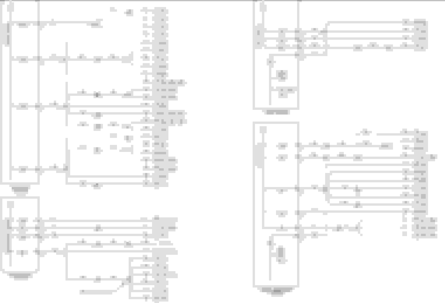
OK. Something is pulling the wire network to ground. It is hard for me to get under the dashboard, so I was looking for another way to move forward. From the following wiring diagram, which is figure 01.4 of the xk8 electrical guide, I see the following:
From xk8 electrical guide, Fig 01.4, there are four fuse box details shown, all related to the ignition switched power distribution.
---
What this allowed me to do is verify B+ (12V) at the source side of the ignition switched power distribution. There are 15 fuses showing. I verified power to 12 of them. This demonstrated to me that power was available on wires WR to many locations. This is important, because WR is the Ignition Switch Position 1 (accessories) wire.
Continuing, there are three WU connections shown. All have covers. I could not get in there with my probe. If I could, and verify presence of B+ or ground, I could conclude state of Ignition Switch Position 2, which is also WU and a switched ignition power distribution network point.
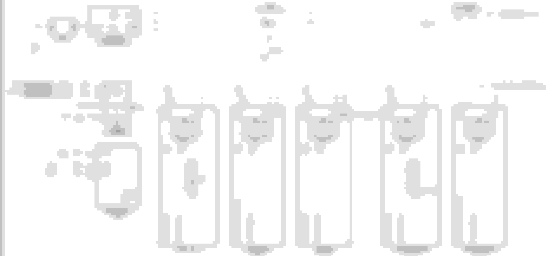
It also appears that emerging from the inertia switch, wire RG (the desired path) continues on to energize relays (figure 01.1/35) in the trunk fuse box and engine compartment fuse box. If I could figure out if these relays are energized, I should be able to conclude RG is active B+ or inactive ground. If B+, everything is working/measuring as it should. I have included the figure 01.1/page 35 following.
Main Power Distribution figure 01.1, page 35 of xk8 Electrical guide. Relays are energized when wires are grounded -- from left to right, RG, WR, WU, RG, and ?
---
So, that's why I desire to remove the yellow guard on the three fuses.
If there is another (accessible) way to verify B+ or ground at these or other locations, please let me know.
And the frustration continues, Bob G in Florida where it is 72F and light drizzle today.
It also appears that emerging from the inertia switch, wire RG (the desired path) continues on to energize relays (figure 01.1/35) in the trunk fuse box and engine compartment fuse box. If I could figure out if these relays are energized, I should be able to conclude RG is active B+ or inactive ground. If B+, everything is working/measuring as it should. I have included the figure 01.1/page 35 following.
Main Power Distribution figure 01.1, page 35 of xk8 Electrical guide. Relays are energized when wires are grounded -- from left to right, RG, WR, WU, RG, and ?
Hi Bob and everyone across the globe rooting for you here.
Ignoring the numbered connections for the moment, you will see that one connection to all of the relays is powered 12V from the high power protection circuit, i.e. always at 12V.
Now, if we want to energise any of these relays, we will ground the other side of the relay coil, which is one of connections 2,10,11,12 and also the un-numbered one which is controlled by the ECM (switched ground).
So, in theory, the passenger side fusebox relay (and hence whatever is supplied by the ENGINE AUXILIARY POWER BUS) will be energised by grounding connection 12 (WR), which in this case happens to connect to the 'aux' on our ignition switch.
Similarly, grounding 2 (WU), 10 (RG) or 11(RG) will energise the drivers' side, engine compartment or trunk fusebox relays. These wires also connect to our ignition switch, either directly or via the inertia switch.
All good, but remember: 2,10,11 and the others are all joined together (either directly or via the inertia switch) and at the moment they are shorted to ground by something other than the ignition switch. So the relays will all be energised, and it is that 'something' that we seek.
We can ignore the relay in the engine management fusebox as that's controlled by the ECM.
What we are trying to achieve is to determine which of the connections from the ignition switch to these relays has a short to ground. The only way to achieve this is to separate them in some way from where they join. That way, you are left with:
where it becomes straightforward to diagnose a short on any of the separate wires.
Hello again Bob. Your guardian angel Michael has, once more, hit the nail on the head . . . providing not only you with a great explanation but also, defusing my frustration . . . your fascination with fuses is precisely the wrong way forward. Moreover, you completely disregarded the critical tests surrounding the inertia switch, which I advised in the lower part of post #49.
The great news is you do not have to go scrabbling behind the dash . . . go straight to the inertia switch . . . the notes to Fig 02.1 tell us where it is, that the 3way connector (AC-10) is coloured Black and it even gives the pinouts and wire codes so you can probe the connector for +12V or 0V. Please, just do it and post back in the form I suggested.
Mate, that's not a slap and I have no wish to offend but please take the time to really understand what I and Michael have been saying about ground seeking switching. Those simple tests in post #49 will point to which of the 3 branches is at fault . . . then, using the "upstream" part of the wiring diagram (which Michael has again displayed at foot of his most recent), it remains a simple matter to test which circuit is at fault, ie already grounded (0V) when it should be floating (+12V).
Pls post your test results. Success is on the tip of your tongue! LOL.
Best wishes,
Ken
Car started, engine running. No warnings, no faults. This would not have been possible without all of your outstanding help.
Here's what happened.
I needed to gain access to driver's fascia fuse box to remove/test inertia switch.
Tried for hours to remove lower side fascia panel without success.
Car was in garage. Too close to wall, so I could not open driver's door sufficiently to gain access to inertia switch wiring.
But I could squeeze my fingers above the inertia switch, so I pressed the reset switch on top of inertia switch. No luck. Dash remained lit.
I needed to PUSH car back and forward to inch it closer to center.
Could not shift out of park without battery connected.
So, plugged in the ignition connector. Connected battery. AND there were no dashboard warning lights.
Stepped on brake. Shifted to Neutral. Still no dashboard warning lights.
So, turned the key and car started up immediately.
---
From page 2459 of the workshop manual:
The inertia switch, when operated, disables the ignition system and fuel pump, releases any locked doors and switches off unnecessary electrical systems.
The inertia switch is located next to the fuse box at the left-hand end of the fascia.
To reset the switch after it has been activated, the rubber cap on the top of the switch is pressed down.
That's what I did.
With power off, I pressed top of inertia switch three times. Each time I could hear the click.
This procedure, coupled with new application of power through ignition circuit, resets everything. This agrees with the Figure 02.1, page 45 diagram from the Electrical guide (posted previously).
Once, reset, and new power applied, the switch floats the GU wire, and activates, to ground, the RG wire.
So, today is Monday and I couldn't be happier. Not only did WE get the car started, but I made several new Jaguar Enthusiast friends from around the globe.
I must add, no where in the workshop manual, or electrical guide, was the condition explained. No where did these guide describe the fault condition (dashboard lights, disabled with ignition on). It only said that the inertia switch disables fuel flow in case of a significant impact event.
All that is left is to reassemble the remaining connectors and covers.
YOU DID IT. Thank you from the bottom of my heart.
And, it is 75F and sunny here. Care to visit sometimes?
I hate to rain on your parade, but I suspect that your ministrations may have cleared the short allowing the car to return to normal, rather than its being due to a simple switch reset.
Originally Posted by Robert Grisar
I must add, no where in the workshop manual, or electrical guide, was the condition explained. No where did these guide describe the fault condition (dashboard lights, disabled with ignition on). It only said that the inertia switch disables fuel flow in case of a significant impact event.
As far as I can see, a tripped inertia switch doesn't result in the fault conditions that you experienced, and I've not read of anyone having the same when their issue has been a tripped switch. Happy to be corrected here.
Anyway, you can't fix a fault that isn't present and it may not come back, so carry on regardless. Please spare a thought for us poor mortals in the higher latitudes while you zoom around with the top down. It's down to 5�C (41F) here tonight
Dear Michael of Jersey, Channel Islands, and all other very helpful Jaguar enthusiasts.
I totally agree with your comments. While the last thing I touched was the inertia switch, the displayed symptoms do not agree with the band-aide.
I plan to reassemble the connectors and covers, and only drive the car on short trips for a few weeks.
As I said earlier, thank you for your patience and incredible knowledge that you shared with me. Nothing feels worse than a Jaguar tucked away in a garage that does not start.
As for the weather, please consider Florida soon, before the 5C in Jersey gets worse. My wife and I love company. Although our place is very modest, we always have room for guests.
Happy again in Florida (78F and sunny today), Bob G.
Hello again Robert. Subject to Michael's caveat (I agree), I am genuinely delighted to hear your outcome. In the happy event you have solved the problem forever . . . can I suggest you have come out wiser, more aware of how to troubleshoot electrical issues, and best of all, made some new friends in several far flung corners of the world. If only temporary . . . then you know where to focus immediately, and preferably out of the garage so you can manipulate yourself to gain better access.
Any outcome that gets you back behind the wheel is great.
Best wishes,
Ken
Thank you again for your patience and support. Getting my XKR started and back on the road is a major victory, and would not have been possible without you help.
Imagine, only 11 time zones between you and Michael, and you are both cut from the same mode: knowledgeable, caring, and sharing. What a great support team.
Today is 80F and sunny. A perfect day to go for a pleasure ride in a Jaguar XKR convertible.
Attached: photo of midnight (the name of our 2001 XKR) following a recent road rally.

 11-10-2017, 10:53 PM


 ) -
) -