When you click on links to various merchants on this site and make a purchase, this can result in this site earning a commission. Affiliate programs and affiliations include, but are not limited to, the eBay Partner Network.
Today I pulled both fronts tires again and gave it all a close look at the front end again after talking to my local Independent Jag Tech shop. The guys said they don't see the need to replace the springs and when all the other parts that wear are done I should be happy with results.
Lots of slop in upper wishbone bushing, and bottom shock bushing. The lower wishbone bushings had minor movement, ball joints had little movement but lower has more angle than I think is normal. I did some measurements on the shock top mount and found a little over 1/4 inch difference on the shock as it protrudes though the mount when car lifted.
I hope to get an inch of the lift out of the rebuild. I did some heavy bounce tests and was surprised at how tight the shocks are at 19 years.
Ordered poly shock top complete assembly in hopes to save me some headaches I read about doing home rebuild, and all the other bits in rubber.
Sourced a clean used oil pan to replace my heavily scraped pan so I don't have to worry about getting a good weld on it.
Ordered up the new engine mount for right side and will be doing power steering cooler hose, sway bar bushings, and engine mount together.
I am noticing a small amount of fluid leak around the steering rack at pinion. Order kit for that as well.
Wow I better spend some time reviewing all the how to articles previously posted to get prepared for this.
Last edited by TexMurphy; 02-16-2016 at 01:08 AM.
Reason: text
Tex, Good luck on all the work ahead. I feel sure you will do fine, try and keep the cuts and bruises down. Wear gloves after you get the ABS lines out of the way, I like to treat those with care, then the shims will require a special touch and curse words when pulling them out and in. The washer on the bolt head side needs to be kept next to the arm as you drive it out.
Couple of days and all will be up to par.
After reading some very good posts here where they did a full rebuild of frontend removing crossbeam I may be coming to the same conclusion due to the total number of items needing repair leaves just the bolts holding crossbeam in place. I think some of this work is easier if cross frame is out of the way, and now after reading it may be I need to do the bushing and mounts of said crossbeam.
To recap I need to do the following.
1. Rebuild steering rack R&R due to slow leak at pinion
2. Replace right engine mount
3. Replace PS cooler hose due to leak at quick connect, and thought I might as well place reservoir supply to complete all rubber hose.
4. Complete bushing and ball joints both sides
5. Brake lines since they look original
If you guys could offer up thoughts on likelihood that both the V mount and crossbeam bushing being bad or how to test?
And if anyone that has done the cross frame drop would like to offer links to their write ups or words of wisdom that I may not be considering. Please feel free to offer up the " Are you crazy statements", I will take the with appreciation.
I have a jack that is built for lifting motorcycles that I think would be perfect for handling the cross frame drop. It has large parallel lifting points so I can put one end directly under and use a pipe or wood across the other end to balance the front edge under the crossbeam bushings.
I could be wrong with the whole idea but I think its possible I have spent more time reading the great posts here than it will take to do the complete removal and that way be 100% new in front suspension.
Further attempt to inspect parts on this car makes me think it is a requirement to have one of the inspection camera of course mine at work is broken and no help. was able to get partial photo of Vee Mounts and metal looks okay and rubber is still seated between one both sides. I have decided against full drop due to worry about other issues I may cause. Most of my parts are in an another box on its way tomorrow so this weekend should be fun.
Let the fun begin.
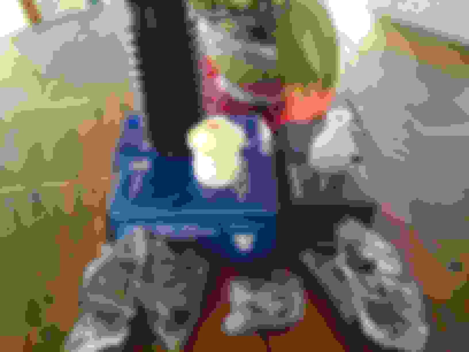
Engine support brace and dual spring compressor in the back of the truck. Pile of parts on the table. Bushings, ball joints, tie rod ends, new shock bottom bush and stop, and top mount, sway bar bushing. My first time holding a shock top in my hand today. I order the Welsh mounts and these things are built like they are going in a tank, they sure seem like an increase in engineering to me. I will post some pics side by side with the originals when I get them out.
So when I finish these parts say lunch time I will start on the engine mount and ps cooler hose, and reservoir to pump hose. That is most likely a lunch some time next week that is.
All front end parts including steering rack are out. Went slow taking photos and bagging a few parts like top wishbone shims. Further testing one lower ball joint had a little movement up down, all freely moved as would be expected but functional all had cracking or completely torn boots, top rear bushing both sides had significant slack.
Found lower wishbone bushing bolts inserted where nuts are in middle so to extract bolts steering rack and cross brace had to come out, good thing I was planning to rebuilding rack. Thinking I should change direction of bolt when installing.
Only really tough part was lower ball joint separation, would not budge with torquing tool and required a few love taps with 2 lb hammer before I got a near explosive separation on both sides. Do be careful on this step. Found tool rental separator set worked for everything but lower ball joints, the one closest to tool shown in JTIS was too small other lever style was low quality and also too small to get a good compression. Went to HF and bought $20 lever style that has two positions that was a good fit and held up well to heavy torque and hammer.
Found top wishbone bolt for bushing a tight fit and slow to extract, a few taps of nut end to get things started then large open end wrench placed behind the bolt head and many more taps yielded success. Mine had very little rust and I think it is most likely grit that is being push through tight tolerances that made a slow job, 20 minutes or so per.
Lower bolts in steering rack where very slow to extract and really worried one would break one off. PB blaster before and during was required, and going slow so things don't heat up and bind further is good idea IMO, I think air tool here would be disaster with a minimum pulling aluminum threads. Upper bolts where not too tight. Overall not a hard removal, and I will be cleaning up threads prior to installation.
Was about 6 hours of work with more than half of the time considering options and checking previous posts, how to posts I had bookmarked, and checking memory with JTIS. Used 1/4 can of PB blaster.
Today will attempt the R&R of bushings and ball joints and rebuild of strut. Keeping option to take parts to local shop if I am beat.
Pretty sure mine is lcd and not back lighting. Mine is like the black a number would be across bottom half of screen. I think it is the lcd itself but possible a good cleaning of board and related pins could fix. Researching it the one in my car is the same part used in several different cars and configurations. Using pictures on ebay where part number is on back you can see how this part was also combined in a configuration that put buttons below mine on top. So many of the less expensive and more plentiful being disassembled is good. I will be waiting on this till later interior work is done as functionality is all still okay.
Actually you will find it is the bulb. My doing the same a just fixed it. There are 2 brown based bulbs. Make sure you use the same color base.
Pretty sure mine is lcd and not back lighting. Mine is like the black a number would be across bottom half of screen. I think it is the lcd itself but possible a good cleaning of board and related pins could fix. Researching it the one in my car is the same part used in several different cars and configurations. Using pictures on ebay where part number is on back you can see how this part was also combined in a configuration that put buttons below mine on top. So many of the less expensive and more plentiful being disassembled is good. I will be waiting on this till later interior work is done as functionality is all still okay.
Actually mine was the same way and I fixed it yesterday by replacing one of the 2 brown based bulbs.
One thing I did want to share about the removal of the long bolt through the upper wishbone bushings. Passenger side easy, drivers side a little harder. Many people posted about having issue with the bolt extraction. I had one side that had some rust between the bushing inner and the sleeve that they slide over. I could tell something was binding to the bolt and just needed to get rubber out of the way so I could see what was turning with the bolt. Overcoming that wasn't too hard after removing the rubber portions of the bushings a little digging at them and cutting. You can cut out the outer washer that is part of the bushing that the rubber is bonded to using some end cutters. There is another washer inside the bushing that is very close tolerance to the bolt. In my case I was able to extract the nut end in pieces within 10 minutes. The other end was a bit more difficult to get working room but after removing rubber and then spinning bolt I could see the one binding. I attempted cutting it with end cutters but only managed to stretch it a little which was what was needed. If the center of bolt between bushings has any corrosion on it will bind as that one did. May be worth trying to clean the bolt up if you are having an issue.
The red arrow was inside the rubber same as black arrow.
Last edited by TexMurphy; 02-21-2016 at 09:18 PM.
Reason: add a photo
So yes I will be polishing the bolt for the upper before it goes back in. I think if someone was struggling getting one out that you could return to original position of bolt and use some sand paper on the bolt.
Had some more fun today after work I had two hours to play before I ran out of light. Pressed out the ball joints in upper wishbone, and the bushings in lower. I did the cut as suggested in JTIS of ball joint with sawzall and then it press out fairly easy with C clamp rental tool with impact wrench assist. My bushings where 3 original plastic and one metal. The plastic where really easy to saw off the flange part to get an edge to work with then pressed out. The metal one was a little more difficult to work with but not horrible. Next up the dreaded lower ball joint.
The cuts as described to allow room for receiver cup, being careful not to cut too deep, finishing separation with hammer and chisel.
One came out whole and the other punched ball through and was a second press of cup portion. After the cut it was only 15 minutes for both.
Well if my day job wasn't consuming all the good day light I could get something done.
Two of the lower bushings in, and one upper ball joint. Too dark to see. No real problem using rental kit from auto parts store on any part except lower ball joint so far. I have an idea for that one, after every shop I talked to wanted almost as much as the 20 ton press from HF to do the work so one more idea then I will own a press if not successful.
upper ball joint in, much easier than the out just take time when you first start to be sure you are going in straight
front bushing, wish they put a little more lip on these bushings, front bushing tried to roll metal lip be sure to keep an eye on it and go slow I had to change the part I was pushing with, rear bushing was about 5 minutes of setup and crank with 1/2 ratchet.
Well done Tex
I figured out a long time ago about the press. It sets idle for months, but when it's called on, I always smile.
Oh, the "C" clap still works best when changing out some stuff, the press takes time to set up and you still need all the spacers when using the press. If you use sockets please use the ones designed for impact tools.
Well another hour of light and the bad boy lower ball joints are out. Cut rim around ball, and extracted said ball. Big drill bit through the middle, sawzall two times getting close to edge about 1/4 inch apart. A few whacks with the 2lb hammer and cold chisel along the edge to loosen the rust. C clamp rental ball joint tool popped it out. Less time than putting together press all tools in stock. Cleaned up the rusty edges with a stone on the cordless drill. One ball joint about 3/4 of the way in when lost the sun again. Cost zero and one more win for the Irish.
Attempted C clamp on lower ball joints, reverted to hammer to drive them in took about 30 love taps with a 2 lbs hammer using edge of hardwood pallet as a backer. Pushed in the other two lower bushings and other upper ball joint. Gave them all a shot of rust-oleum so ready for assembly this weekend
Tex, looking good.
I do have one question on your parts. In thread #46, the top shock mounts showing have the two metal plates already pop riveted together. Did yours come this way, as the plates look new?
I ask because we had some problems with the rivets breaking and wondered if Welsh changed the way of doing things.
After reading some of the posts about the rebuild kits, I wasn't interested in that fight and was considering the stock style when I ran across these priced at the same price range and what looks like would be a better design for longevity. Hopefully they don't transfer more road feel to the car. They are built very well with good clean studs another point I read about some of the aftermarket where they painted threads that broke during installation. I think this is a perfect location for poly in a non-rotational location, not sold on poly bushing as I have had some squeaks when used in sway bar links in the past.

 02-16-2016, 01:02 AM