
My project...
#121
 08-15-2012, 08:58 AM

Your welcome Blue.
I'd rather see the parts go to a good purpose then sit in the box collecting dust. Just send me your mail to address and I will most likely send the parts in a USPS priority mail box, if it fits it ships. I think that is the cheapest way to go. I will let you know the shipping total and you can send me money, check, or Paypal it to me if you have a Paypal account.
Cheers
Tim V.
The following users liked this post:
mohrd (08-15-2012)
#122
08-15-2012, 09:24 AM

Your welcome Blue.
I'd rather see the parts go to a good purpose then sit in the box collecting dust. Just send me your mail to address and I will most likely send the parts in a USPS priority mail box, if it fits it ships. I think that is the cheapest way to go. I will let you know the shipping total and you can send me money, check, or Paypal it to me if you have a Paypal account.
Cheers
Tim V.
I'd rather see the parts go to a good purpose then sit in the box collecting dust. Just send me your mail to address and I will most likely send the parts in a USPS priority mail box, if it fits it ships. I think that is the cheapest way to go. I will let you know the shipping total and you can send me money, check, or Paypal it to me if you have a Paypal account.
Cheers
Tim V.
Mailing address:
PO box 2236
Lexington, SC 29071
Again, thanks so much!!
Cheers!!
The following users liked this post:
mohrd (08-15-2012)
#123
08-15-2012, 09:33 AM
Good early day everyone!!
While I was out hunting down a wiring harness, I remembered to snap a few pics of the oil pan and other "off-roading" damage... I would almost swear this car was stolen and just abused for hours... The fiberglass protection thing under the bumper and radiator is swiss cheese... Every bolt that hides under that cover is poking thru... The support beam that goes under and in front of the oil pan has a nice bend in it... I couldn't get the bend in the PS tie rod, but it looks as if it happened backing out, or being pulled out of somewhere... The fact they would pick that to hook on to doesn't surprise me... This has oil in it and doesn't leak! It does look like it's cut all the way through, but it's holding...
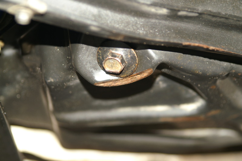
Looking at this picture closer, it looks as if this bar came back far enough to tag the oil pan pretty good... Oh well!! The pan will be replaced soon enough... It is nice to be able to get to this without having to drop a front axle and diff, or work around a cross member...
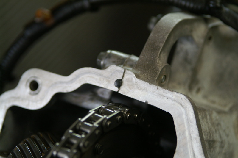
While I was in there, I gave an educated guess to what 45 deg ATDC from cylinder 1 bank 1 would be (PS headlight cylinder according to my specs pdf) *Thanks WhiteXKR for that info*... This is the image that shined through the access hole...
It isn't a triangle like the book says, but I can see where this might be the correct image... I took this for a weld as they all do look pretty much like this... SOOOO, if you are doing this job, you might find a ROUND "triangular arrow indent"...
That's it for now...
Cheers everyone!!!
While I was out hunting down a wiring harness, I remembered to snap a few pics of the oil pan and other "off-roading" damage... I would almost swear this car was stolen and just abused for hours... The fiberglass protection thing under the bumper and radiator is swiss cheese... Every bolt that hides under that cover is poking thru... The support beam that goes under and in front of the oil pan has a nice bend in it... I couldn't get the bend in the PS tie rod, but it looks as if it happened backing out, or being pulled out of somewhere... The fact they would pick that to hook on to doesn't surprise me... This has oil in it and doesn't leak! It does look like it's cut all the way through, but it's holding...
Looking at this picture closer, it looks as if this bar came back far enough to tag the oil pan pretty good... Oh well!! The pan will be replaced soon enough... It is nice to be able to get to this without having to drop a front axle and diff, or work around a cross member...
While I was in there, I gave an educated guess to what 45 deg ATDC from cylinder 1 bank 1 would be (PS headlight cylinder according to my specs pdf) *Thanks WhiteXKR for that info*... This is the image that shined through the access hole...
It isn't a triangle like the book says, but I can see where this might be the correct image... I took this for a weld as they all do look pretty much like this... SOOOO, if you are doing this job, you might find a ROUND "triangular arrow indent"...
That's it for now...
Cheers everyone!!!
Last edited by bluexk8ragtop; 08-15-2012 at 09:42 AM.
#124
08-15-2012, 09:42 AM

Veteran Member
Atlas TD6MR Portable Scissor Lift
When you get ready to buy a lift, check this out. I picked mine up with my Ford van, weighs a little over 1000 lbs. Greg Smith is in Norcross (Atlanta). It only raises 4.5 ft., but that's enough to get underneath. You can move it around on the floor and just load it in the back of a van if you relocate.
RJ______________
97 XK8 85K mi
#125
08-15-2012, 10:46 AM
Veteran Member
While I was in there, I gave an educated guess to what 45 deg ATDC from cylinder 1 bank 1 would be (PS headlight cylinder according to my specs pdf) *Thanks WhiteXKR for that info*... This is the image that shined through the access hole...
It isn't a triangle like the book says, but I can see where this might be the correct image... I took this for a weld as they all do look pretty much like this... SOOOO, if you are doing this job, you might find a ROUND "triangular arrow indent"...

That's it for now...
Cheers everyone!!!
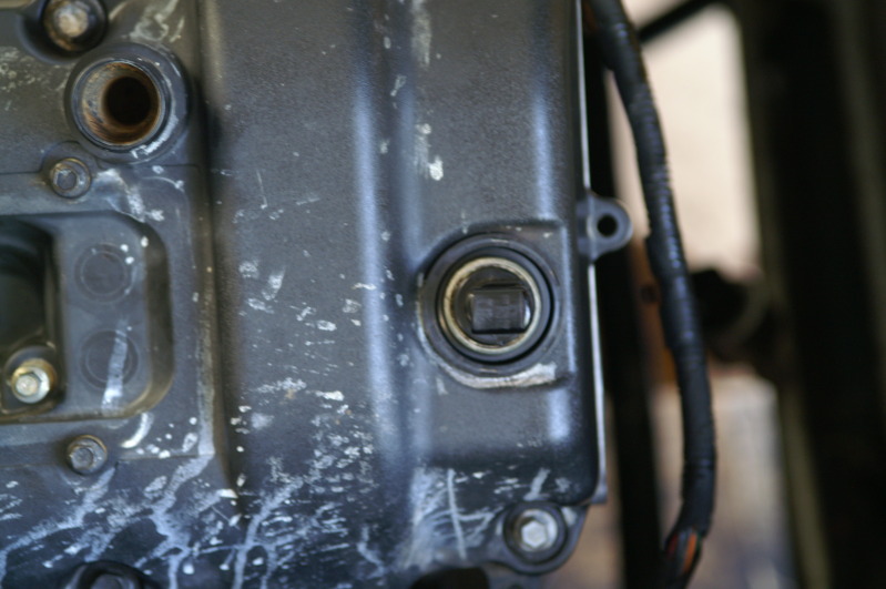
I would expect it to line up with a threaded hole for the crank locking tool if this was the correct position.
#127
08-15-2012, 12:03 PM
The locking tool still goes in where the CPS is and goes thru the "tone ring" in the flywheel... The mark is just an indicator where to stop the flywheel... I have to take the CPS out and install the 303-531 tool in the CPS location...
Thanks so much everyone for the help on this one!!! You all ROCK!!! (it's a good thing - Military...) I'll post pictures as soon as I get them...
Cheers!!!
Last edited by bluexk8ragtop; 08-15-2012 at 12:05 PM.
#128
08-15-2012, 12:09 PM
#129
08-15-2012, 12:31 PM
Veteran Member
It�s not worth the money for a XK8 imho, but there are several options.
Cheapest is to find an earlier XJS lsd, that can be built in with some small mods, of you can get a Quaife ATB unit which can be built into the stock diff housing, or at the other end of the scale a OS Giken TCD which I am using now.
Cheapest is to find an earlier XJS lsd, that can be built in with some small mods, of you can get a Quaife ATB unit which can be built into the stock diff housing, or at the other end of the scale a OS Giken TCD which I am using now.
#130
08-15-2012, 06:57 PM
It�s not worth the money for a XK8 imho, but there are several options.
Cheapest is to find an earlier XJS lsd, that can be built in with some small mods, of you can get a Quaife ATB unit which can be built into the stock diff housing, or at the other end of the scale a OS Giken TCD which I am using now.
Cheapest is to find an earlier XJS lsd, that can be built in with some small mods, of you can get a Quaife ATB unit which can be built into the stock diff housing, or at the other end of the scale a OS Giken TCD which I am using now.
Cheers!!!
#131
08-15-2012, 08:36 PM
Good day everyone!!!
I'm going to ruin the surprise by telling you all that I am not using ANY timing tools to do this job... Am I crazy?! Well, maybe... Not about getting this right though... The tools are like the Stop-N-Shop... You pay for the convience of getting what you need quickly... Well, I can do the same thing, but it will require more of my undivided attention... And I have full confidence the DS is done perfectly... I am waiting on my new tappets (lifters) to arrive before I can do the PS... So, I'm on pause for the moment...
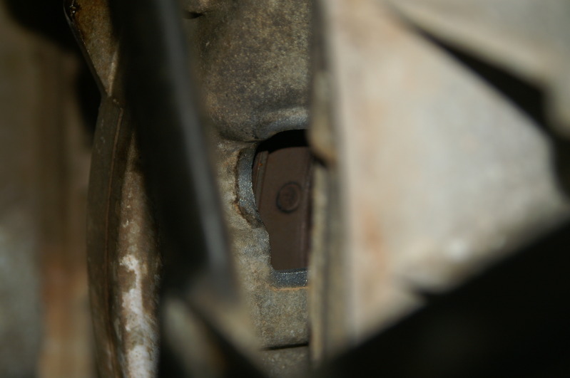
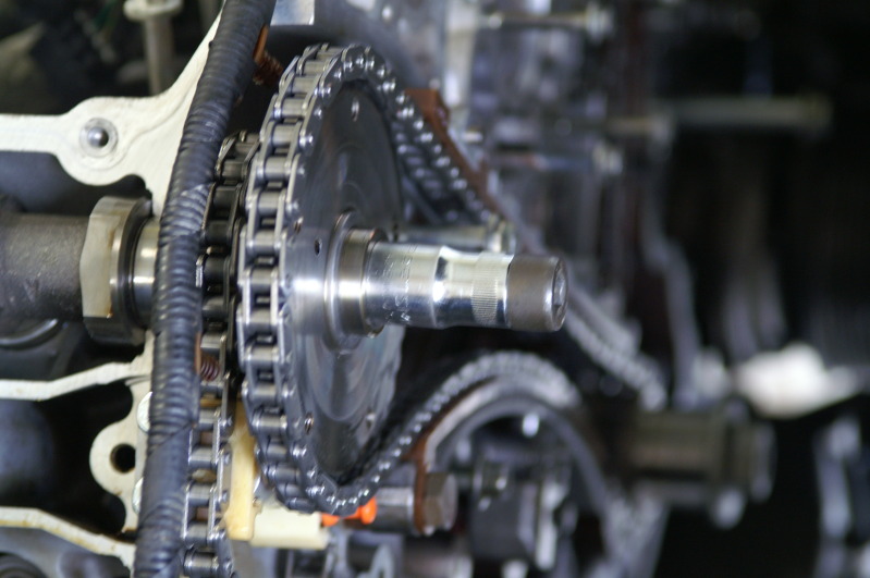
Here is what the estimated guess got me on 45* ATDC... This proves two things... WhiteXKR knows his stuff!! Thanks again for that info!! And, Avos gave us the proof of what to look for on the flywheel when the 'mark' is missing!! Thanks for that photo!! (it took me five tries to get this pic)

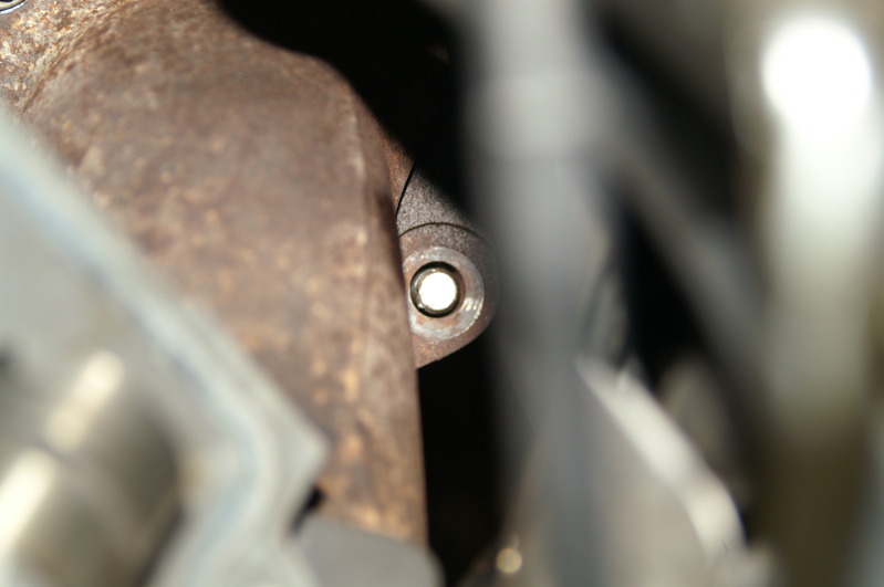
And here is where that curved hole should be... I missed it by thaaaaaaaaaaaat much...

You ever have one of those days when you'd wished you'd quit while you were ahead?! I should have known better!! Now what to do about this?!
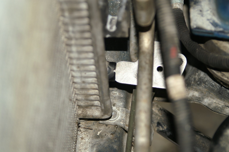
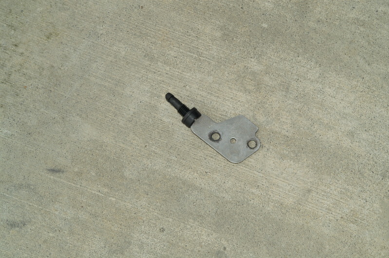
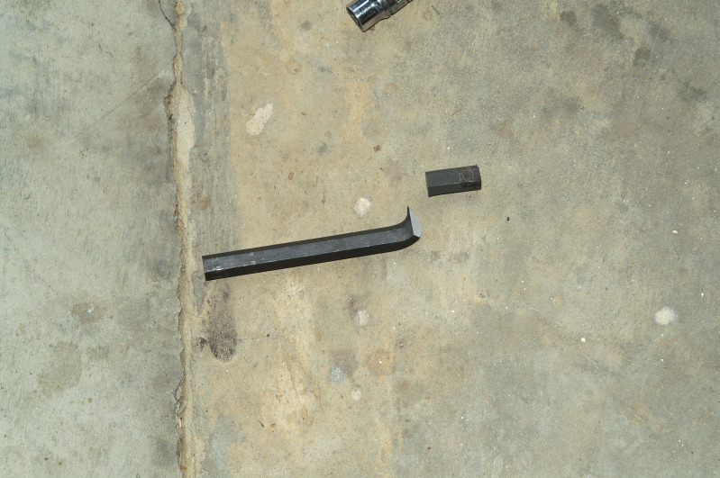
Here is what you can do with those plates that use to be under the Gen I chain tensioners... In the event you have to drain your radiator, you have the tool needed!! Really, I just wanted to get rid of that crap that was in the coolant system... A thorough coolant flush is in order!!
Okay guys and gals...... I don't want anyone to use my method to time their Jag... For all the normal reasons... Get the tools and follow the directions... Please...
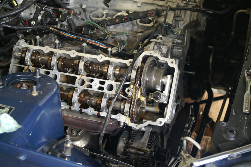
This is my thought process on this... Set the crank (thanks WhiteXKR and Avos!!) - done... Set the cams (DS done; PS waiting on parts)... Lock the cams (done for the ones installed)... Make sure the VVT is fully seated (hold the cam and turn the outter VVT body clock-wise) Or what you should do is use the tool and rotate "anti-clockwise)... Either method pulls the in-out piston fully in... I mentioned in a previous post that it was near impossible to rotate the VVT assy on the camshaft... Well, there was a reason for that... When I put the VVT assy back together and installed it on the sprocket, they weren't lined up perfectly... When I loosened the VVT assy, everything lined up and they rotate freely!!! Okay, at this point the cams are locked, the chains are on, and the crank is set...
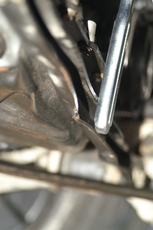
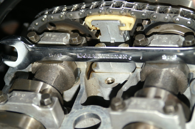
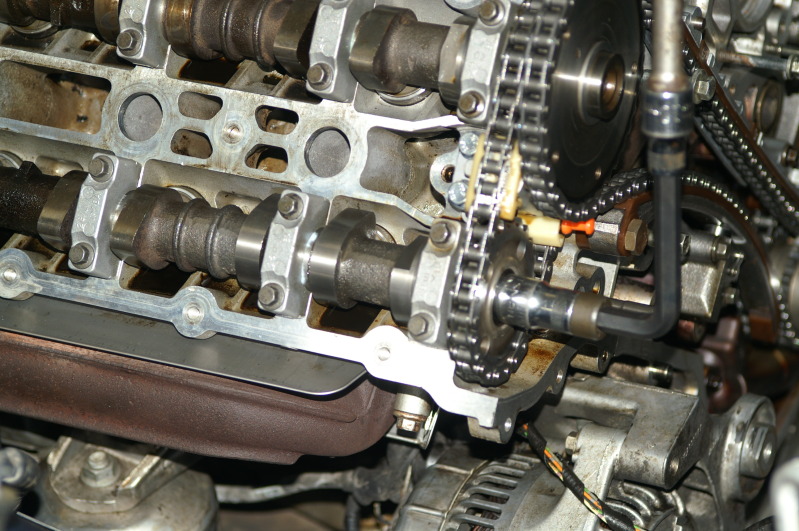
If you think about the goal, you won't be moving the crank... You just need the chains tight and that isn't going to affect anything if you do that before you tighten the cam shaft bolts... The cam shafts are locked, so they won't move anyway... Here is how I did the cam shaft adjustments... I used this 13mm 1/2 drive socket to turn the shaft to it's proper place... With no cam bolts tight, the sprockets aren't going to move at all... You can use the exhaust bolt to do the adjustments... Same threads and it's considerably longer, and solid unlike the intake cam bolt...
And my high tech alignment tool to verify the cam flats are perfect!!
The thing I did that isn't outlined in the procedure is when you can pull the pins... So, I pulled them after I knew everything was set for that side... I didn't have to use any shims between the tensioner and guide because there was no way I would've gotten one in there... The tensioner did all that work for me... And the same for the secondary tensioners... That has to be applied to keep the variable from messing up the difference...

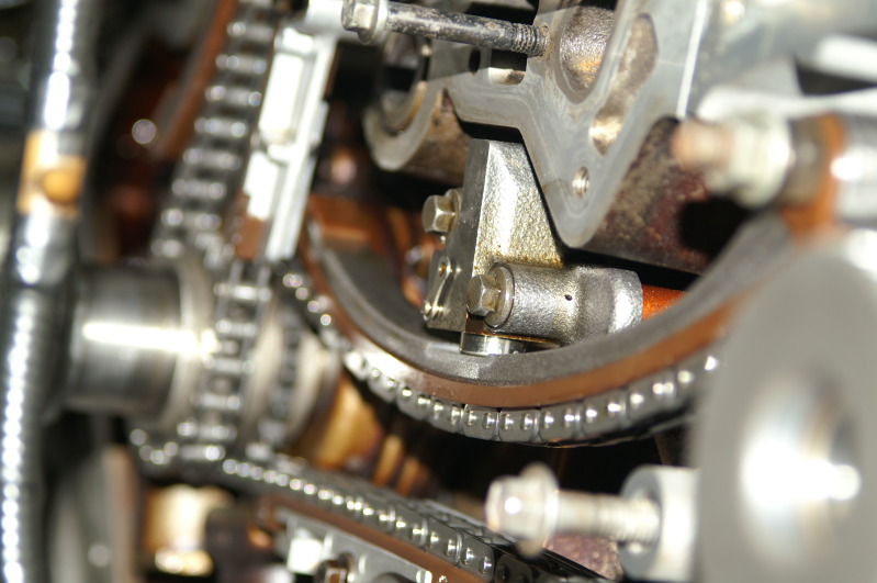
This one is done...
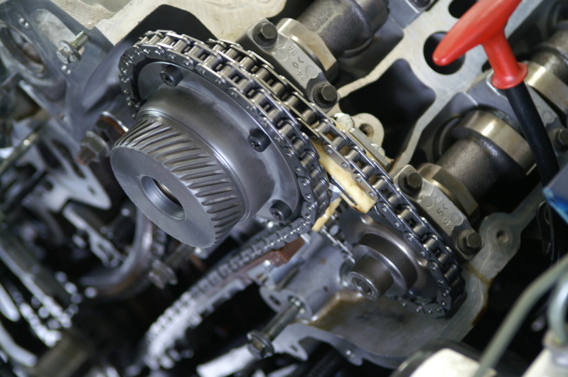
This one still has the secondary pin because I can't install the cam until I get the lifters... But the cam is set and locked... Verification will take place when I get the other cam installed...
Well, that is it for now... I was really hoping I would get the lifters today... Once I get everything set, I will release the cams and rotate the motor by hand... I will verify the cam flats are perfect (all four) and the crank is in the right spot by checking that access hole... Honestly guys and gals, this isn't the first time I've used this method to time one of my cars... I had a 98 BMW 540i that needed guides... Same method, but the flats were at the back of the cam... I used a 6 inch metal ruler as my straight edge for that one...
Cheers everyone!!!
I'm going to ruin the surprise by telling you all that I am not using ANY timing tools to do this job... Am I crazy?! Well, maybe... Not about getting this right though... The tools are like the Stop-N-Shop... You pay for the convience of getting what you need quickly... Well, I can do the same thing, but it will require more of my undivided attention... And I have full confidence the DS is done perfectly... I am waiting on my new tappets (lifters) to arrive before I can do the PS... So, I'm on pause for the moment...
Here is what the estimated guess got me on 45* ATDC... This proves two things... WhiteXKR knows his stuff!! Thanks again for that info!! And, Avos gave us the proof of what to look for on the flywheel when the 'mark' is missing!! Thanks for that photo!! (it took me five tries to get this pic)
And here is where that curved hole should be... I missed it by thaaaaaaaaaaaat much...
You ever have one of those days when you'd wished you'd quit while you were ahead?! I should have known better!! Now what to do about this?!
Here is what you can do with those plates that use to be under the Gen I chain tensioners... In the event you have to drain your radiator, you have the tool needed!! Really, I just wanted to get rid of that crap that was in the coolant system... A thorough coolant flush is in order!!
Okay guys and gals...... I don't want anyone to use my method to time their Jag... For all the normal reasons... Get the tools and follow the directions... Please...
This is my thought process on this... Set the crank (thanks WhiteXKR and Avos!!) - done... Set the cams (DS done; PS waiting on parts)... Lock the cams (done for the ones installed)... Make sure the VVT is fully seated (hold the cam and turn the outter VVT body clock-wise) Or what you should do is use the tool and rotate "anti-clockwise)... Either method pulls the in-out piston fully in... I mentioned in a previous post that it was near impossible to rotate the VVT assy on the camshaft... Well, there was a reason for that... When I put the VVT assy back together and installed it on the sprocket, they weren't lined up perfectly... When I loosened the VVT assy, everything lined up and they rotate freely!!! Okay, at this point the cams are locked, the chains are on, and the crank is set...
If you think about the goal, you won't be moving the crank... You just need the chains tight and that isn't going to affect anything if you do that before you tighten the cam shaft bolts... The cam shafts are locked, so they won't move anyway... Here is how I did the cam shaft adjustments... I used this 13mm 1/2 drive socket to turn the shaft to it's proper place... With no cam bolts tight, the sprockets aren't going to move at all... You can use the exhaust bolt to do the adjustments... Same threads and it's considerably longer, and solid unlike the intake cam bolt...
And my high tech alignment tool to verify the cam flats are perfect!!
The thing I did that isn't outlined in the procedure is when you can pull the pins... So, I pulled them after I knew everything was set for that side... I didn't have to use any shims between the tensioner and guide because there was no way I would've gotten one in there... The tensioner did all that work for me... And the same for the secondary tensioners... That has to be applied to keep the variable from messing up the difference...
This one is done...
This one still has the secondary pin because I can't install the cam until I get the lifters... But the cam is set and locked... Verification will take place when I get the other cam installed...
Well, that is it for now... I was really hoping I would get the lifters today... Once I get everything set, I will release the cams and rotate the motor by hand... I will verify the cam flats are perfect (all four) and the crank is in the right spot by checking that access hole... Honestly guys and gals, this isn't the first time I've used this method to time one of my cars... I had a 98 BMW 540i that needed guides... Same method, but the flats were at the back of the cam... I used a 6 inch metal ruler as my straight edge for that one...
Cheers everyone!!!
Last edited by bluexk8ragtop; 08-15-2012 at 08:40 PM.
#132
08-16-2012, 06:16 AM

Join Date: Oct 2007
Location: PHX some of the time
Posts: 117,242
Received 6,306 Likes
on
5,494 Posts
No you're not crazy, as long as you ensure that nothing moves as you go and that everything is lined up when your done you will be golden.
Back in the dark days of the infernal combustion engine we didn't get fancy schmantzy tools just a scratch and a pop mark here and there which had to match.
Back in the dark days of the infernal combustion engine we didn't get fancy schmantzy tools just a scratch and a pop mark here and there which had to match.
#133
08-16-2012, 08:11 PM
No you're not crazy, as long as you ensure that nothing moves as you go and that everything is lined up when your done you will be golden.
Back in the dark days of the infernal combustion engine we didn't get fancy schmantzy tools just a scratch and a pop mark here and there which had to match.
Back in the dark days of the infernal combustion engine we didn't get fancy schmantzy tools just a scratch and a pop mark here and there which had to match.
Thanks!!!
Cheers!!
#134
08-16-2012, 08:34 PM
Good day everyone!!
Bad news... I didn't get any parts... No parts, no additional progress... Short of installing the water pump, which would be in the way, there really isn't much more I can do... I had to start work today anyway... I have two different suppliers sending me what I need... So the first one that gets here wins...
So, what I have to do to finish this up is:
Set the timing for the PS after I get my two small parts...
Lock the cam bolts in...
Rotate the motor by hand three complete revolutions (redundancy is all)...
Re-locate 45* ATDC, and then verify the cam flats are still perfect...
Put the timing chain cover on...
Top off the clean oil, making sure everything in the heads gets a good soaking in the process (not down the spark plug holes!!!!)...
Spin the motor with the starter to prime the oil passages again...
Pull out the compression tester and annotate the PSI of each cylinder...
Then it's pretty much reassembly at this point...
I have a good feeling I can get all this done tomorrow or the next day if I get these parts... But, I'm not going to rush it... Right now all I want to do is wash it!!! And I can't do that unless it runs OR I won't be able to get it back where it is... It's killing me not being able to do anything to it... I really hope all the error messages in the dash go away like the gearbox message did when I installed a good shifter... I just started my job at, of all places, a complete car care center... Which is a good thing because I need three tires and an inner tie rod...
Does anyone else have this thick plastic on their headlights that seems to be held in place with tons of sticky goo?! I was considering pulling that off to remove goo... I love the fact that the headlights are glass...
Okay, that's it for now...
Cheers everyone!!!
#135
08-17-2012, 02:06 AM
It�s not worth the money for a XK8 imho, but there are several options.
Cheapest is to find an earlier XJS lsd, that can be built in with some small mods, of you can get a Quaife ATB unit which can be built into the stock diff housing, or at the other end of the scale a OS Giken TCD which I am using now.
Cheapest is to find an earlier XJS lsd, that can be built in with some small mods, of you can get a Quaife ATB unit which can be built into the stock diff housing, or at the other end of the scale a OS Giken TCD which I am using now.
Just to be more specific, you want a diff from an X300 thats the old XJ not an XJS they have a different diff completely, if you get one you also need the front section of the rear cage the diff goes through, the casings are the same but the diff nose is about an 1" offset, also try to get one close to 3:09 otherwise you will need to get the TCM programmed. You will also need a XKR prop or make something up, your current prop is a large aluminium tube about 4-5" diameter, with the diff nose offset this causes rubbing issues
#136
08-17-2012, 07:04 PM
Just to be more specific, you want a diff from an X300 thats the old XJ not an XJS they have a different diff completely, if you get one you also need the front section of the rear cage the diff goes through, the casings are the same but the diff nose is about an 1" offset, also try to get one close to 3:09 otherwise you will need to get the TCM programmed. You will also need a XKR prop or make something up, your current prop is a large aluminium tube about 4-5" diameter, with the diff nose offset this causes rubbing issues
Thanks again!!
Cheers!!
#137
08-17-2012, 07:07 PM
Good day everyone!!
Sorry, no pictures yet... I got my parts in though... I might have everything right tomorrow and possibly have it running... I will probably have an exhaust leak, but that is what happens when you have three out of four bolts holding the manifold to the cats (Yep, both sides)...
See everyone tomorrow...
Cheers!!
#138
08-17-2012, 11:27 PM
Veteran Member
The Quiafe and OS slide in the current housing no modifications needed, another one is gripper diffs in the UK, this is the lowest cost unit I know of that also slides in.
#139
08-18-2012, 09:54 PM
Good day everyone!!
I want to apologize for getting these on here so late... I was going to wait until tomorrow to post them, but then that would delay everyone seeing them for more than 12 hours... So, here they are at 11 PM...
The day started out great... I broke my 10mm allen wrench, but that made it easier to use the torque wrench... I didn't make it out to the dealership to get the exhaust bolts... And after the sun went down, I stopped taking pictures... If you haven't had to tackle those cam position sensor connectors, you are lucky!! I didn't even get an "after" picture of the DS valve cover... Nor one of the intake manifold... I have over 54 pictures, but I don't think I willl post all of them...
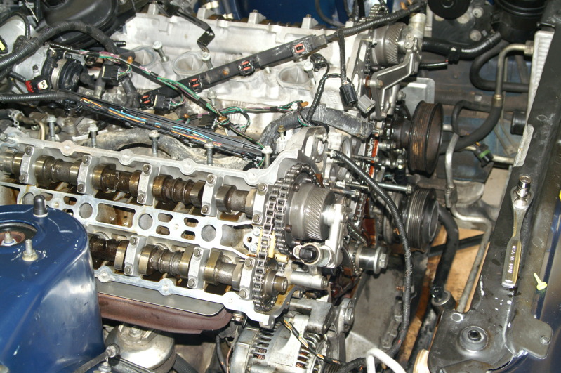
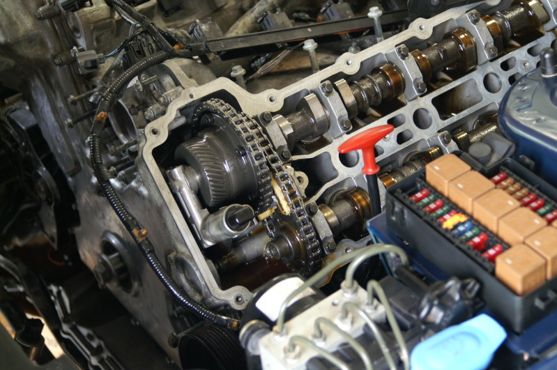
First things first... The new parts are in and the exhaust cam is in place... I put the cam in close to where it should be, better to have valves up then down... This was the only cam that came close to valves and piston contact if you go too far with the adjustment... Here is the inital setup; moving the cam into position...

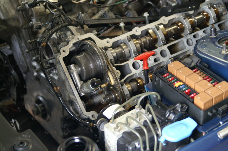
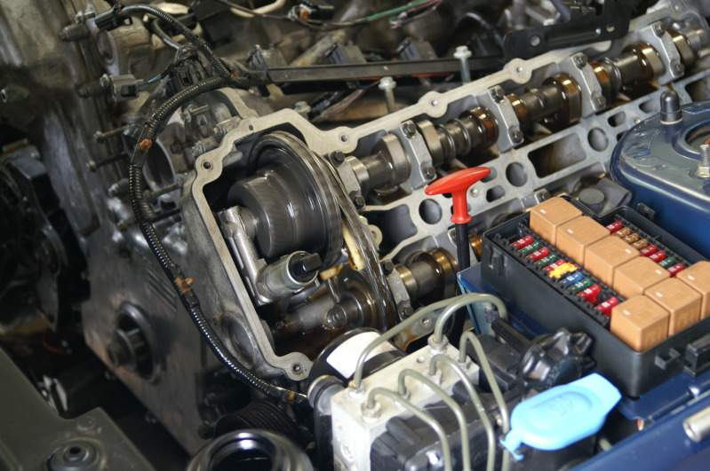
I didn't get a shot of the actual length of the piston stop thingy I'm using, but there isn't much room as this piston is on it's way up on the exhaust stroke... This is prior to the cam being in position... Oil these puppies up before moving anything... See the lifter drop in the next shot as I get the cam right...


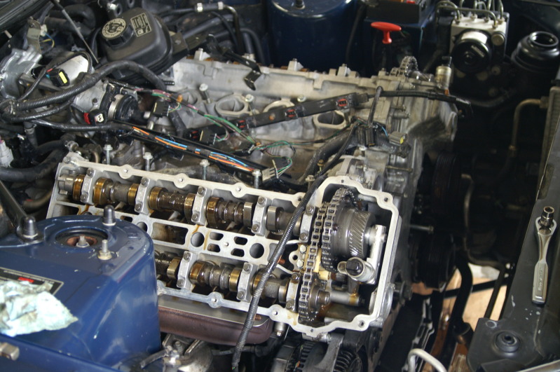
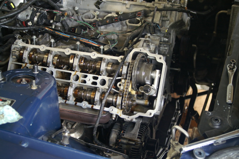
This is close, but as you can see they aren't perfect... I got them perfect after this shot... The secondary tensioner still has the pin installed in this picture... I pulled the pin before locking the cam bolt down... Notice the chain has a little slack in it... That is why I think the procedure should have you pull these pins after cam lock-down is done, before cam bolt is tightened...

And then the end of my allen wrench... So, I took the short part and made an end for a 10mm socket... Too easy...
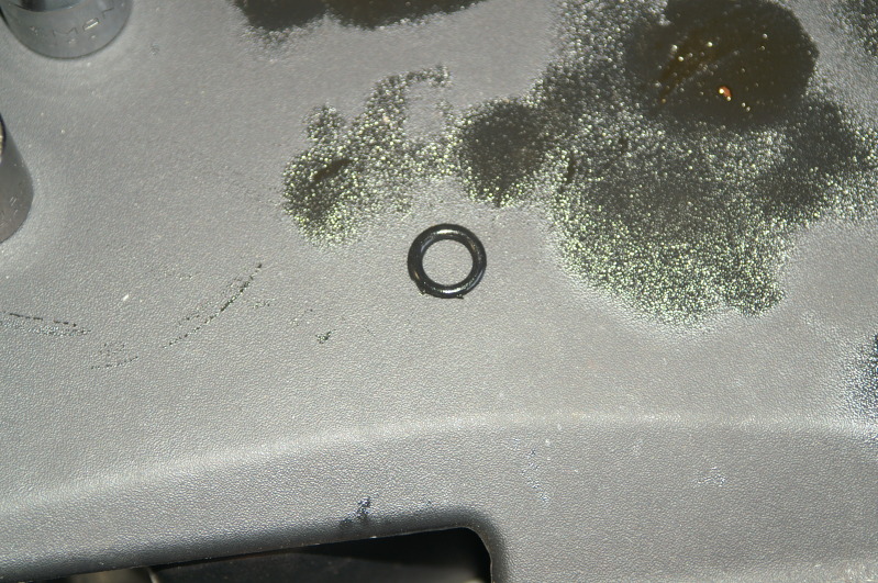
I think this O-ring is too big for the application... This goes between the block and the VVT oil carrier... I think it cracked the carrier due to it's thickness... I shaved it down just a little... You can't even see the crack in the picture... I don't think it will make a difference...

This is after everything was timed and the oil system was more or less primed... Okay, I had my beautiful wife help me with this part... I got oil all over when the secondary tensioners purged all their air and let the oil fly... Fly it did too... I had to put the chain cover on at this point...
Chain cover on and priming the oil again... There will be a lot of repeated shots... I just let the camera click away as the motor was spinning... First one, motor isn't moving...


And the other side... (I took twice as many of these in motion, but... more ins't always better...)


There are some good things about the new head gaskets... And some bad... The chain cover has dowels for location... This put the top surface of the cover higher than the level of the heads... Additionally, the VVT carrier is mounted to the block, and the cams are on the heads... The carrier also has dowels... It will be interesting to see if the VVT's give me issues... I doubt it... We'll see...
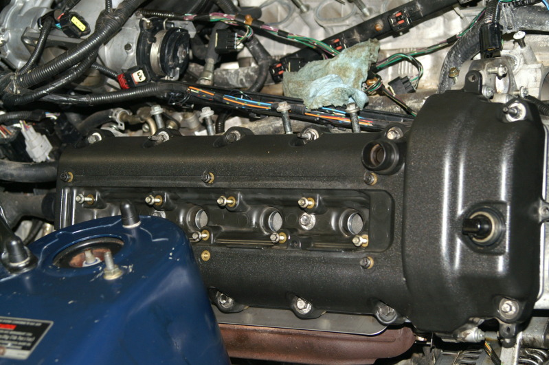
Here is the valve cover going on... This is a before picture...
And the three long bolts for the PS cover... The DS had four; same three here and one for the oil checker thingy... First, third, and fifth from front to back on the top row for both covers...

And you want to try to get this as centered as possible... Just cause you can...
And the other side...

All clean!!!! The other side looks the same... (more pictures tomorrow)...
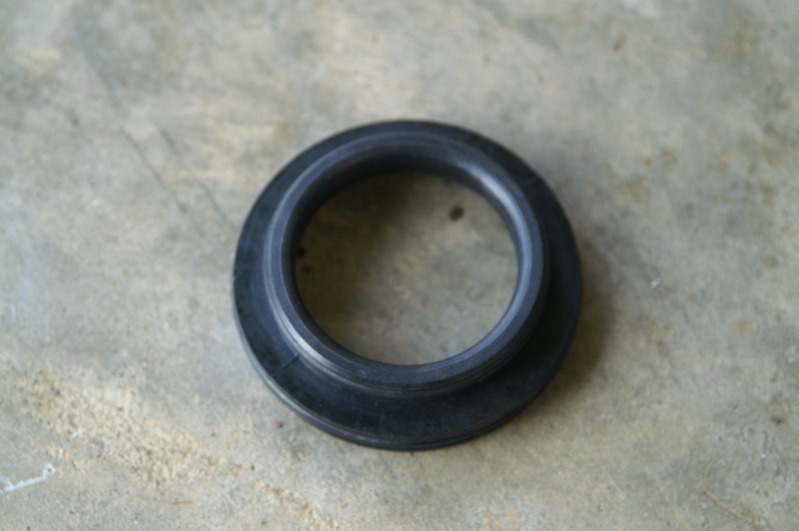
And this should come as a spare part that you can purchase... This was the only thing on my original pump that was bad...

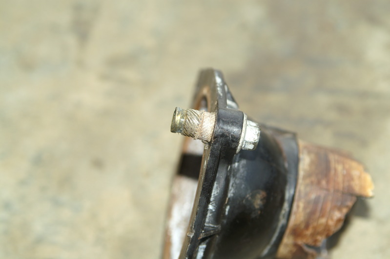
And thank you so much original owner!!! This again is why........ I'll keep my comments to myself... I can't get the bolts loose... the threaded part spins in the plastic...


And then this happened, not that it mattered... The replacement metal version has already been purchased... Now the wait for another part... Or three...


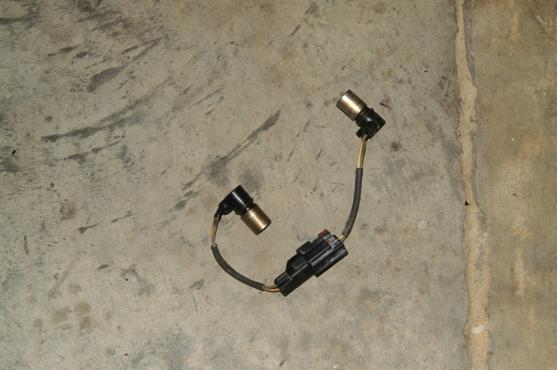
And the NEW knock sensors... Just like the melted ones I took out, without the melted parts... Huge bag for such a small item...

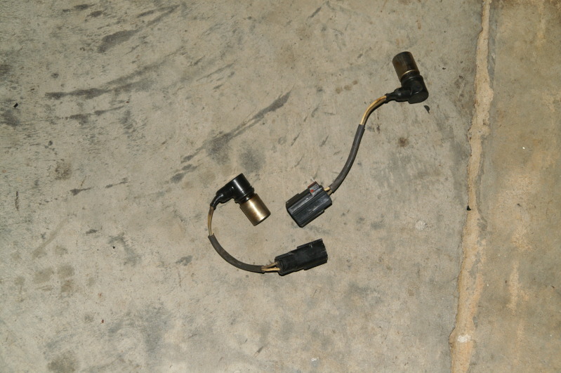
And this is why there is a right and a left cam position sensor... The connectors are side specific... You can snap the right and left together...
Well, that does it for the pictures... I did get the intake on, all the pullies on, the harmonic balancer, the fans installed, and nearly all the connectors connected... The cooling system is keeping me from moving ahead... I can start it, I guess, but I won't let it run for more than a second or two... I don't have access to the compression tester... I'm just going to install the plugs and see if I have normal compression before adding the fuel (fuel relay is still pulled)... I will have to pull the intake to get the coolant parts installed, but I may have to pull the intake anyway... The previous guy pulled the threads from the bottom aluminium part of the throttle body... I guess if I had to replace that part of the intake, I would replace the whole thing due to the heat melting those two ports and that one small crack at the injector...
Funny part of the day was when the wife returned with the plugs and coolant... The plugs she got were exactly like the ones I pulled from the car... Oh, in case I didn't mention this before, NEVER EVER install a plug (that needs a washer) without the washer... They are a bear to get loose afterwards... Aske me how I know!?! The original guy installed one plug without the washer... Maybe it bounced under the car and he didn't feel like bending over to get it... After all, it's not his car...
I'm still getting all the warning messages, but I still have connectors off and no coolant... I don't understand the "stability control fault" and "traction control fault" messages... Does that mean I have a bad wheel sensor or does it have to reset after I start moving it again?!
Okay everyone, I'm off to bed... Have a great weekend!!! AND an even better upcoming week!!
Cheers everyone!!!
I want to apologize for getting these on here so late... I was going to wait until tomorrow to post them, but then that would delay everyone seeing them for more than 12 hours... So, here they are at 11 PM...
The day started out great... I broke my 10mm allen wrench, but that made it easier to use the torque wrench... I didn't make it out to the dealership to get the exhaust bolts... And after the sun went down, I stopped taking pictures... If you haven't had to tackle those cam position sensor connectors, you are lucky!! I didn't even get an "after" picture of the DS valve cover... Nor one of the intake manifold... I have over 54 pictures, but I don't think I willl post all of them...
First things first... The new parts are in and the exhaust cam is in place... I put the cam in close to where it should be, better to have valves up then down... This was the only cam that came close to valves and piston contact if you go too far with the adjustment... Here is the inital setup; moving the cam into position...
I didn't get a shot of the actual length of the piston stop thingy I'm using, but there isn't much room as this piston is on it's way up on the exhaust stroke... This is prior to the cam being in position... Oil these puppies up before moving anything... See the lifter drop in the next shot as I get the cam right...
This is close, but as you can see they aren't perfect... I got them perfect after this shot... The secondary tensioner still has the pin installed in this picture... I pulled the pin before locking the cam bolt down... Notice the chain has a little slack in it... That is why I think the procedure should have you pull these pins after cam lock-down is done, before cam bolt is tightened...
And then the end of my allen wrench... So, I took the short part and made an end for a 10mm socket... Too easy...
I think this O-ring is too big for the application... This goes between the block and the VVT oil carrier... I think it cracked the carrier due to it's thickness... I shaved it down just a little... You can't even see the crack in the picture... I don't think it will make a difference...
This is after everything was timed and the oil system was more or less primed... Okay, I had my beautiful wife help me with this part... I got oil all over when the secondary tensioners purged all their air and let the oil fly... Fly it did too... I had to put the chain cover on at this point...
Chain cover on and priming the oil again... There will be a lot of repeated shots... I just let the camera click away as the motor was spinning... First one, motor isn't moving...
And the other side... (I took twice as many of these in motion, but... more ins't always better...)
There are some good things about the new head gaskets... And some bad... The chain cover has dowels for location... This put the top surface of the cover higher than the level of the heads... Additionally, the VVT carrier is mounted to the block, and the cams are on the heads... The carrier also has dowels... It will be interesting to see if the VVT's give me issues... I doubt it... We'll see...
Here is the valve cover going on... This is a before picture...
And the three long bolts for the PS cover... The DS had four; same three here and one for the oil checker thingy... First, third, and fifth from front to back on the top row for both covers...
And you want to try to get this as centered as possible... Just cause you can...
And the other side...
All clean!!!! The other side looks the same... (more pictures tomorrow)...
And this should come as a spare part that you can purchase... This was the only thing on my original pump that was bad...
And thank you so much original owner!!! This again is why........ I'll keep my comments to myself... I can't get the bolts loose... the threaded part spins in the plastic...
And then this happened, not that it mattered... The replacement metal version has already been purchased... Now the wait for another part... Or three...
And the NEW knock sensors... Just like the melted ones I took out, without the melted parts... Huge bag for such a small item...
And this is why there is a right and a left cam position sensor... The connectors are side specific... You can snap the right and left together...
Well, that does it for the pictures... I did get the intake on, all the pullies on, the harmonic balancer, the fans installed, and nearly all the connectors connected... The cooling system is keeping me from moving ahead... I can start it, I guess, but I won't let it run for more than a second or two... I don't have access to the compression tester... I'm just going to install the plugs and see if I have normal compression before adding the fuel (fuel relay is still pulled)... I will have to pull the intake to get the coolant parts installed, but I may have to pull the intake anyway... The previous guy pulled the threads from the bottom aluminium part of the throttle body... I guess if I had to replace that part of the intake, I would replace the whole thing due to the heat melting those two ports and that one small crack at the injector...
Funny part of the day was when the wife returned with the plugs and coolant... The plugs she got were exactly like the ones I pulled from the car... Oh, in case I didn't mention this before, NEVER EVER install a plug (that needs a washer) without the washer... They are a bear to get loose afterwards... Aske me how I know!?! The original guy installed one plug without the washer... Maybe it bounced under the car and he didn't feel like bending over to get it... After all, it's not his car...
I'm still getting all the warning messages, but I still have connectors off and no coolant... I don't understand the "stability control fault" and "traction control fault" messages... Does that mean I have a bad wheel sensor or does it have to reset after I start moving it again?!
Okay everyone, I'm off to bed... Have a great weekend!!! AND an even better upcoming week!!
Cheers everyone!!!
Last edited by bluexk8ragtop; 08-18-2012 at 10:24 PM. Reason: errors...
#140
08-19-2012, 08:27 PM
Good day everyone!!
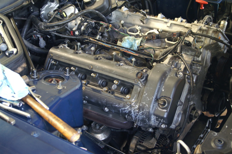
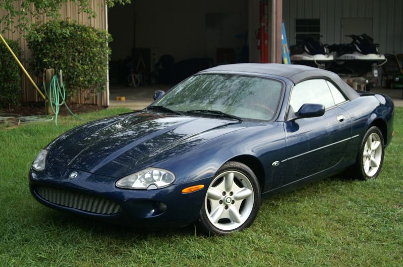
Well, I washed my car today!!!!!! I wonder how many out there understood what that meant right away?!
Here she is all clean...


And here is the starting point for today... No coolant/thermostat housing and using the old cam pos sensors... I have replacements on the way... New knock sensors and I had to make a vac line today... Looks pretty good... Be even better if it will hold up to the heat of the block under the intake manifold...
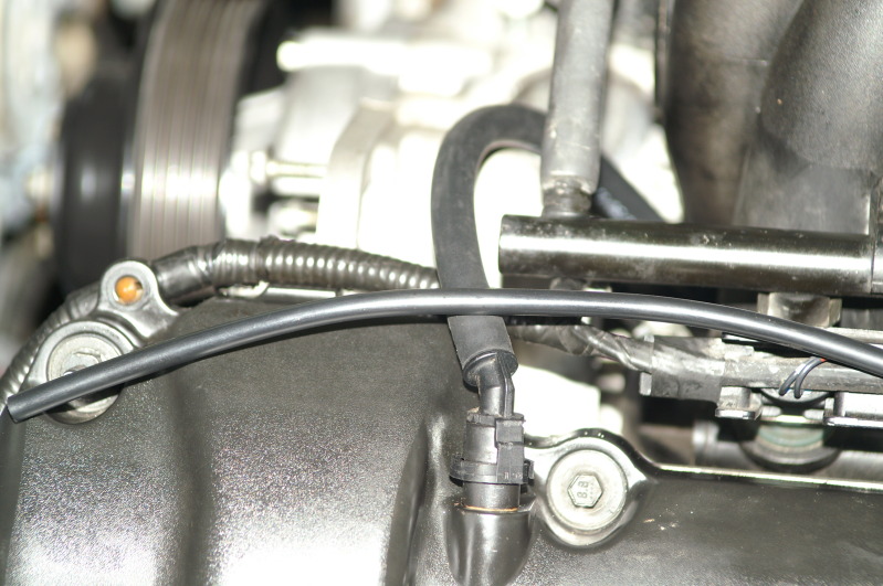
I replaced this kind of line...
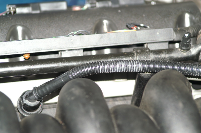
With this acutual vac line... and the plastic piece inside for reinforcement...
This is another surprise I got upon reassembly...

Here is the bolt that has pulled threads... It is as tight as I can get it... Which is not very tight...

Here is the connector I had to use pliers to click closed... then the red tab moves forward to lock it...

I did what I said and installed the plugs with no fuel... The wife turned over the motor with the key and all sounded good... I added the fuel (installed relay and purged air) and started it... I had her shut it down right away if it started... It started right up and I had her shut it down right away... I let the air purge from where ever in the oil system for a few seconds... Then I repeated the process but had it run a little longer... It started right up again and sounded ultra smooth... Two seconds and I had her shut it down... Again, I let it sit for a few before repeating the process... My wife noted the error message said the battery wasn't charging... So, I told her I'd fix that by installing the belt... Since that was pretty much the first thing I took off, I had to figure out how it went back on... I got it and the error message went away the next time she started it... I filled the PS system first as it was bone dry when I bought the car... I had her turn the wheel with it running, lock to lock to purge the air out of the steering system...
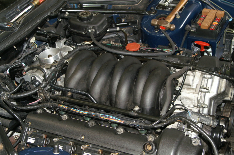
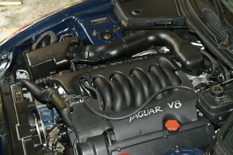
Just prior to initial test run...


After test run... Cleaning up the odds and ends... Coil covers on and motor covers installed (one is from a 97 so it doesn't match exactly)...


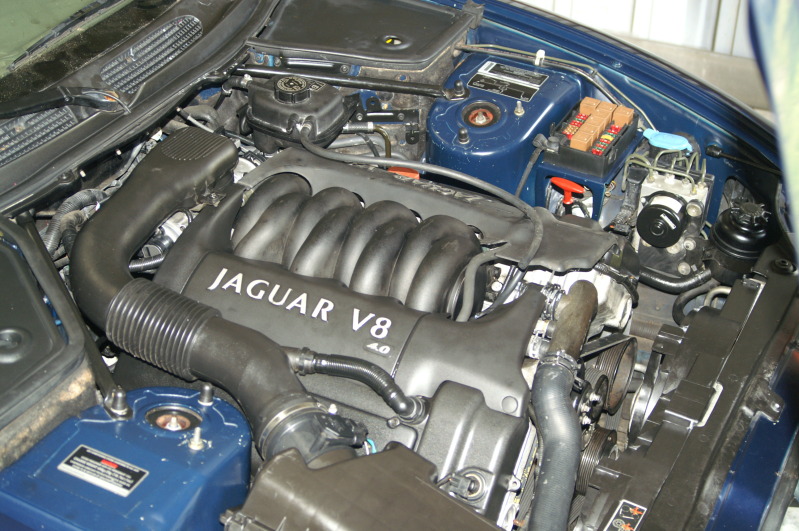
And the belt routing... If you can see it in the picture...
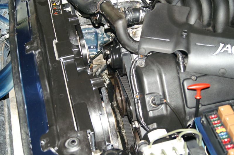
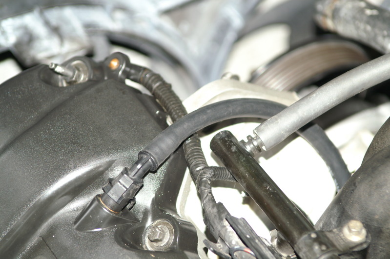
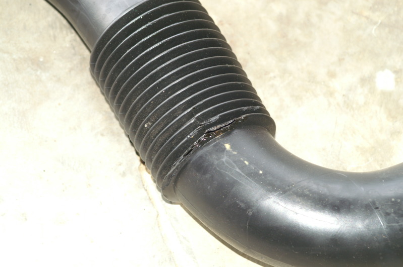
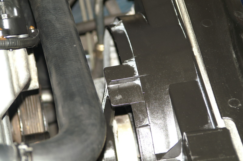
Here is something I found that I think all of you should take a look at soon... Maybe this is very well known issue that didn't make it to the PO of this car, but this is again something I found upon reassembly... Bottom coolant hose is nearly worn through by the fan shroud... Some mod needs to be done here...

Well, that is it guys and gals... It has been fun!!! I will update this when I get the thermostat housing... I have to get another vac line made for the other side that I broke installing the new side... Go figure!! I still have two exhaust manifold bolts out, but on order... I'm gonna source a new intake manifold just for peace of mind... And I will replace the hose that has a spot missing from the fan shroud... New bottom clamp too!! I hate messing with those squeeze clamps in tight spaces...
Take care everyone!!
Cheers!!!
Well, I washed my car today!!!!!! I wonder how many out there understood what that meant right away?!
Here she is all clean...
And here is the starting point for today... No coolant/thermostat housing and using the old cam pos sensors... I have replacements on the way... New knock sensors and I had to make a vac line today... Looks pretty good... Be even better if it will hold up to the heat of the block under the intake manifold...
I replaced this kind of line...
With this acutual vac line... and the plastic piece inside for reinforcement...
This is another surprise I got upon reassembly...
Here is the bolt that has pulled threads... It is as tight as I can get it... Which is not very tight...
Here is the connector I had to use pliers to click closed... then the red tab moves forward to lock it...
I did what I said and installed the plugs with no fuel... The wife turned over the motor with the key and all sounded good... I added the fuel (installed relay and purged air) and started it... I had her shut it down right away if it started... It started right up and I had her shut it down right away... I let the air purge from where ever in the oil system for a few seconds... Then I repeated the process but had it run a little longer... It started right up again and sounded ultra smooth... Two seconds and I had her shut it down... Again, I let it sit for a few before repeating the process... My wife noted the error message said the battery wasn't charging... So, I told her I'd fix that by installing the belt... Since that was pretty much the first thing I took off, I had to figure out how it went back on... I got it and the error message went away the next time she started it... I filled the PS system first as it was bone dry when I bought the car... I had her turn the wheel with it running, lock to lock to purge the air out of the steering system...
Just prior to initial test run...
After test run... Cleaning up the odds and ends... Coil covers on and motor covers installed (one is from a 97 so it doesn't match exactly)...
And the belt routing... If you can see it in the picture...
Here is something I found that I think all of you should take a look at soon... Maybe this is very well known issue that didn't make it to the PO of this car, but this is again something I found upon reassembly... Bottom coolant hose is nearly worn through by the fan shroud... Some mod needs to be done here...
Well, that is it guys and gals... It has been fun!!! I will update this when I get the thermostat housing... I have to get another vac line made for the other side that I broke installing the new side... Go figure!! I still have two exhaust manifold bolts out, but on order... I'm gonna source a new intake manifold just for peace of mind... And I will replace the hose that has a spot missing from the fan shroud... New bottom clamp too!! I hate messing with those squeeze clamps in tight spaces...
Take care everyone!!
Cheers!!!
Last edited by bluexk8ragtop; 08-19-2012 at 08:36 PM.