When you click on links to various merchants on this site and make a purchase, this can result in this site earning a commission. Affiliate programs and affiliations include, but are not limited to, the eBay Partner Network.
1997 XK8 convertible 4.0 (non supercharger) left hand drive. I am installing a new power steering pump. The pump is in place, but I can’t seem to get the long bolts to “catch.” The ones that pass through the bracket and engine block, and into the pump body itself. They are fully seated, but just continue to turn. I know they aren’t stripped, because I haven’t encountered any resistance. And yes, the fixing nuts are on the new pump. Thanks everyone.
Last edited by GGG; 11-04-2021 at 06:12 PM.
Reason: Add 'RESOLVED' to thread title
Well……..It’s difficult to see down in there, even with a good light. The next morning, I went out there with a fresh attitude, and just stared at it, I guess hoping it would fix itself. Then I noticed the front of the pump wasn’t quite in the same parallel plane as the other pulleys. I didn’t have it lined up correctly, even though it was snug and had no movement. 🤬. So I removed it, started over, and got it right. By the way, I would never have attempted this repair without the many posts I studied here on the forum. Thanks so much, everybody!
Well……..It’s difficult to see down in there, even with a good light. The next morning, I went out there with a fresh attitude, and just stared at it, I guess hoping it would fix itself. Then I noticed the front of the pump wasn’t quite in the same parallel plane as the other pulleys. I didn’t have it lined up correctly, even though it was snug and had no movement. 🤬. So I removed it, started over, and got it right. By the way, I would never have attempted this repair without the many posts I studied here on the forum. Thanks so much, everybody!
I need to replace or reseal mu OAS pump. I spent weeks gathering all the tech info and suggestions from members, but somehow it has all disappeared....including the hard copies of the JTIS drawings and instructions I printed out. Maybe it's a sign from God I shouldn't even try this, but I'm not going to pay the local Jagshop $1500 for a rebuilt pump and labor. I've done everything else on this car and I'd like to think I can handle this if I can get my hands down in there again.
But I have NO real reference anymore. I was wondering if you had any links to the JTIS procedure or any of the posted methods to doing this. I wish someone would make a video.
You can download the Workshop Manual for your car at the link below. However, the 1999 Second Edition has a more detailed and complete procedure for replacing the power steering pump beginning on pdf page 709, so download both manuals for your library:
Replacing the pump isn't difficult, but the working position is awkward and getting the high pressure line disconnected and reconnected is fiddly. One way to approach it is to just loosen the high pressure hose fitting while the pump is still mounted, then remove the pump mounting bolts. This will give you some wiggle room for better access to unthread the high-pressure fitting and to access the low-pressure hose clamp.
Also, be careful with your oil dipstick tube once you disconnect its bracket. It's easy to bend, and if you move it too much, you may disturb the O-ring seal at the lower end of the tube which may then leak. Or better, plan on replacing the O-ring.
It's also a good idea to replace the low-pressure hose, since it tends to harden over time and lose its ability to seal at the reservoir and pump ends. In fact, before you commit to replacing the pump, clean the fluid off the low pressure hose and pump and drive the car for a day, then check to be sure the fluid leak is not actually from one or both ends of the low-pressure hose.
Cheers,
Don
Thanks, Don;
For some reason the JTIS Adobe pages I had downloaded before did not work. This time I printed them out and saved online copies in several files.
Your advice will help, but I sure wish there were some good pics and even a video like there are for the R&R of the ABS module.
As I am looking at the JTIS drawing of the radiator and fan assembly, I'm pretty sure I'll need to remove the fan and bracket, but I don't see any identification of the location of the nuts/bolts/clips/screws that hold the assembly in there. Any info will help.
As I am looking at the JTIS drawing of the radiator and fan assembly, I'm pretty sure I'll need to remove the fan and bracket, but I don't see any identification of the location of the nuts/bolts/clips/screws that hold the assembly in there. Any info will help.
Hi Ken,
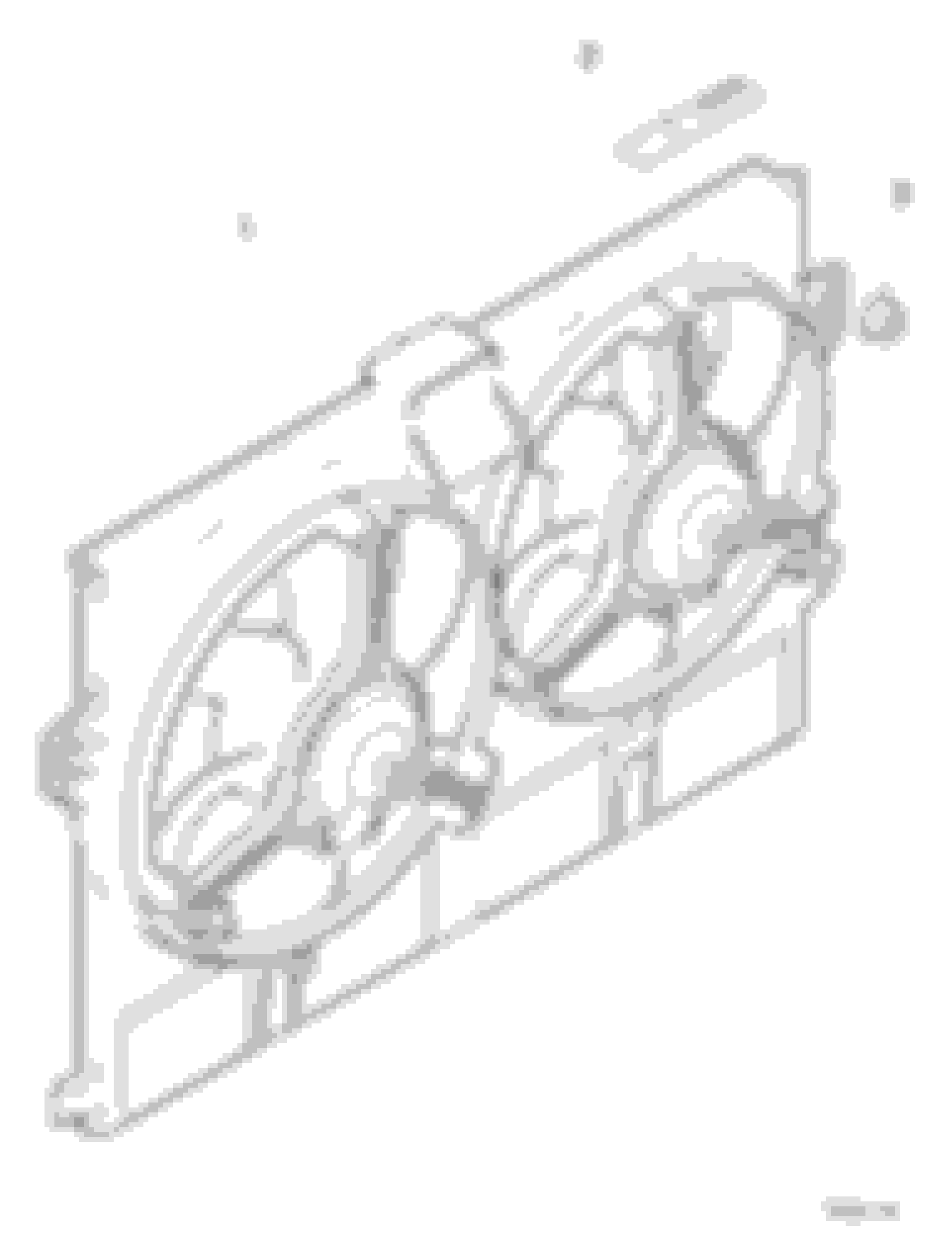
I don't recall having to remove the radiator fan/shroud assembly to R&R the P/S pump, but if you need to do so on your car, the fan shroud is secured by one nut on each side, about 5 inches down from the top corner. The nuts (Part 3 in the diagram) thread onto studs to secure the shroud. The slots in the upper tabs on the shroud fit over the studs. With the nuts removed, you can tilt the shroud rearward and pull the tabs at the lower corners out of their slots. You have to disconnect the fan electrical connector and you may find one or more cooler hoses clipped to the lower edge of the shroud. Also, you will probably have to tilt and wiggle the shroud one way and another to work the tabs past various hoses, cooler lines, etc.
For what it's worth, I always found JTIS to be incomplete and not very easy to use, so I primarily reference the Workshop Manual, Electrical Guide, Technical Introductions, Vehicle Specification Booklets and the Electronic Parts Catalog (EPC) or the parts diagrams at parts.jaguarlandroverclassic.com (where I grabbed the diagram above).
Cheers,
Don
First, your information has been very helpful.Thank you.
This job has been long and hard (surely a crude comment for this), and we keep running into stupidly contrary components and invisible locations of fasteners. We managed to get the belt dropped, the pulley off, and then had to cut the reservoir-to-pump hose because neither clamp would release. We did not remove the fan assembly. Getting the right combination of wrenches, sockets, and extensions is a PITA.
We were set to unbolt the pump and hopefully remove it, but the oil dipstick tube seems to be very securely attached down where we cannot see it or get hands on it. There is the wiring harness for the camshaft solenoid attached right where we need to get at the dipstick and rear of the pump. We disconnected the harness at the clip, but can't move it too far because it seems pretty brittle. Again I tried to remove the top radiator hose clamp from the tower so I could move the hose out of the way, but those clamps are like battleship ammo straps. I couldn't get a tool on it so I removed the coolant tank-to-tower end to get IT out of the way. I couldn't budge the battleship clamp. SOB!
So we stopped for the day. Question: HOW DO WE GET AT THE DIPSTICK TUBE TO RELEASE IT FROM THE PUMP WITHOUT DAMAGING IT?
Do we jigger the pump out aways and pull it forward/twist enough to get at the clip? What does that do to the high pressure line WHICH WE ALSO CANNOT GET AT THAT BOTTOM CONNECTION POINT. Can that line be pulled forward enough to get at the outlet nut without damaging the line? The JTIS order of operation only works IF you can get at the tube and line connections. We can't even SEE them or get our hands down in there. again!
Maybe there is a magic wand the members pass around to help make these stupidly engineered things accessible?
We were set to unbolt the pump and hopefully remove it, but the oil dipstick tube seems to be very securely attached down where we cannot see it or get hands on it. There is the wiring harness for the camshaft solenoid attached right where we need to get at the dipstick and rear of the pump. We disconnected the harness at the clip, but can't move it too far because it seems pretty brittle. Again I tried to remove the top radiator hose clamp from the tower so I could move the hose out of the way, but those clamps are like battleship ammo straps. I couldn't get a tool on it so I removed the coolant tank-to-tower end to get IT out of the way. I couldn't budge the battleship clamp. SOB!
So we stopped for the day. Question: HOW DO WE GET AT THE DIPSTICK TUBE TO RELEASE IT FROM THE PUMP WITHOUT DAMAGING IT?
Do we jigger the pump out aways and pull it forward/twist enough to get at the clip? What does that do to the high pressure line WHICH WE ALSO CANNOT GET AT THAT BOTTOM CONNECTION POINT. Can that line be pulled forward enough to get at the outlet nut without damaging the line? The JTIS order of operation only works IF you can get at the tube and line connections. We can't even SEE them or get our hands down in there. again!
Hi Ken,
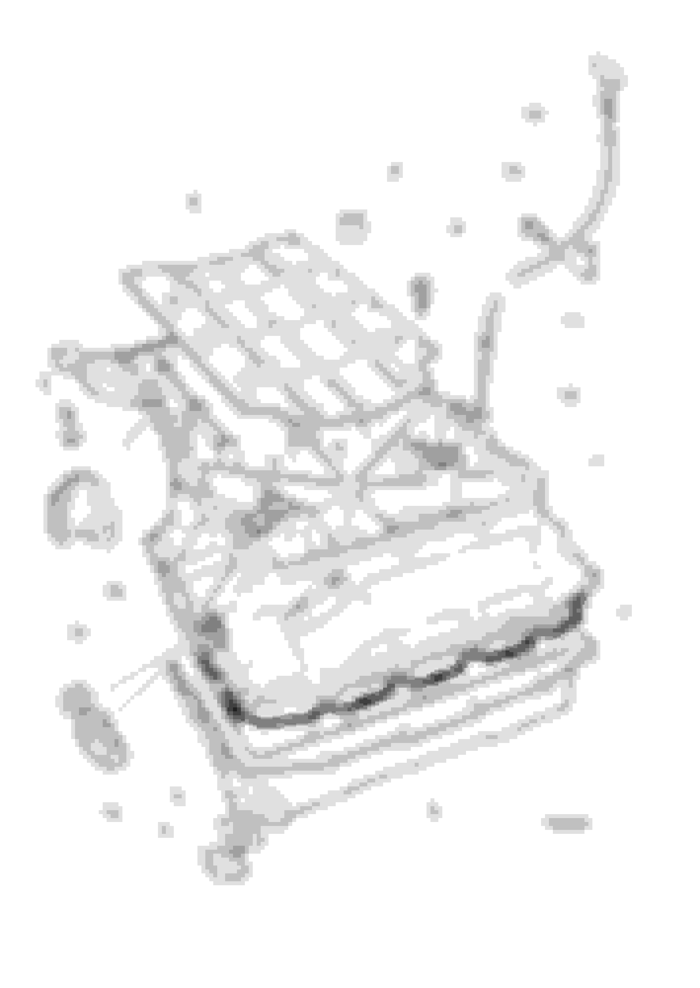
It's been awhile since I did an X100 P/S pump but I do remember that the working position is awkward and a lot of the fasteners have to be accessed by feel. I am fortunate to have an inspection endoscope that comes in handy in these situations. An inspection mirror will help also. The oil dipstick tube mounts with one screw through a flange (Part 13 below). Once that screw is removed, you can usually move the tube slightly, or if you want it out of the way, you can pull it up and out of the crankcase. But you'll want to replace the O-ring at the lower end of the tube (Part 12). And reinserting the tube into the crankcase is another blind operation:
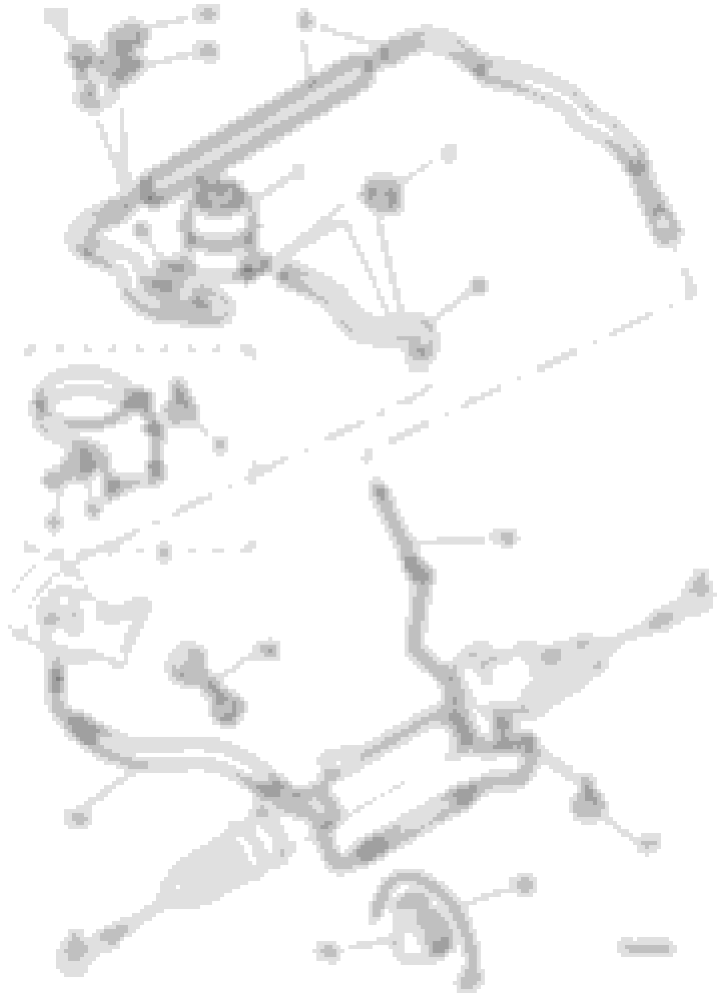
The high-pressure hose (Part 13 below) has a rubber section that will give you a little movement once the pump is disconnected. But I find it easier to loosen the high-pressure hose fitting while the pump is still mounted, assuming you can get a flare nut/line wrench on it. Worst case, you can disconnect the hoses at the steering rack end by removing the single screw (Part 17) that secures them, but I can't remember how accessible it is:
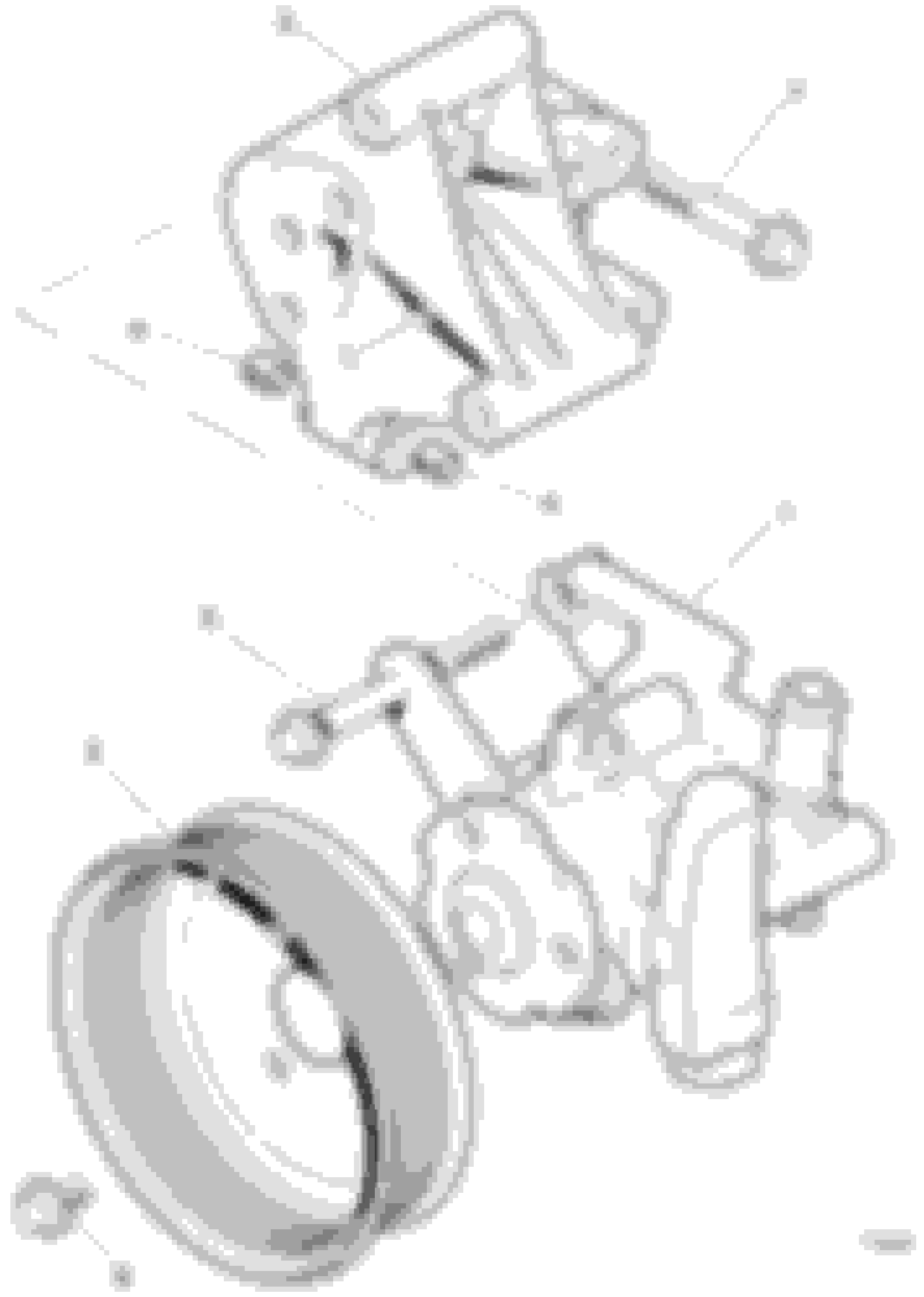
It's not absolutely necessary to remove the pump pulley, but it will give you much easier access to the high-pressure hose fitting and help you see the pump mounting bolts. It's much easier to loosen the pulley screws while the accessory drive belt is still installed. Quick, jerking movements of your wrench will be more likely to loosen the pulley screws than slow, gradual pressure, which will be more likely to rotate the pulley. Once the screws are loose, you can remove the belt and then remove the pulley. This diagram shows how the pump and mounting bracket are oriented. There are two mounting bolts for the pump (Part 5), but only one is shown in the diagram. The other one is lower on the same side of the pump (the left side when viewing the pump from the front of the car). The bolts pass through sleeves cast into the mounting bracket (Part 3) and thread into captive nuts on the rear flange of the pump:
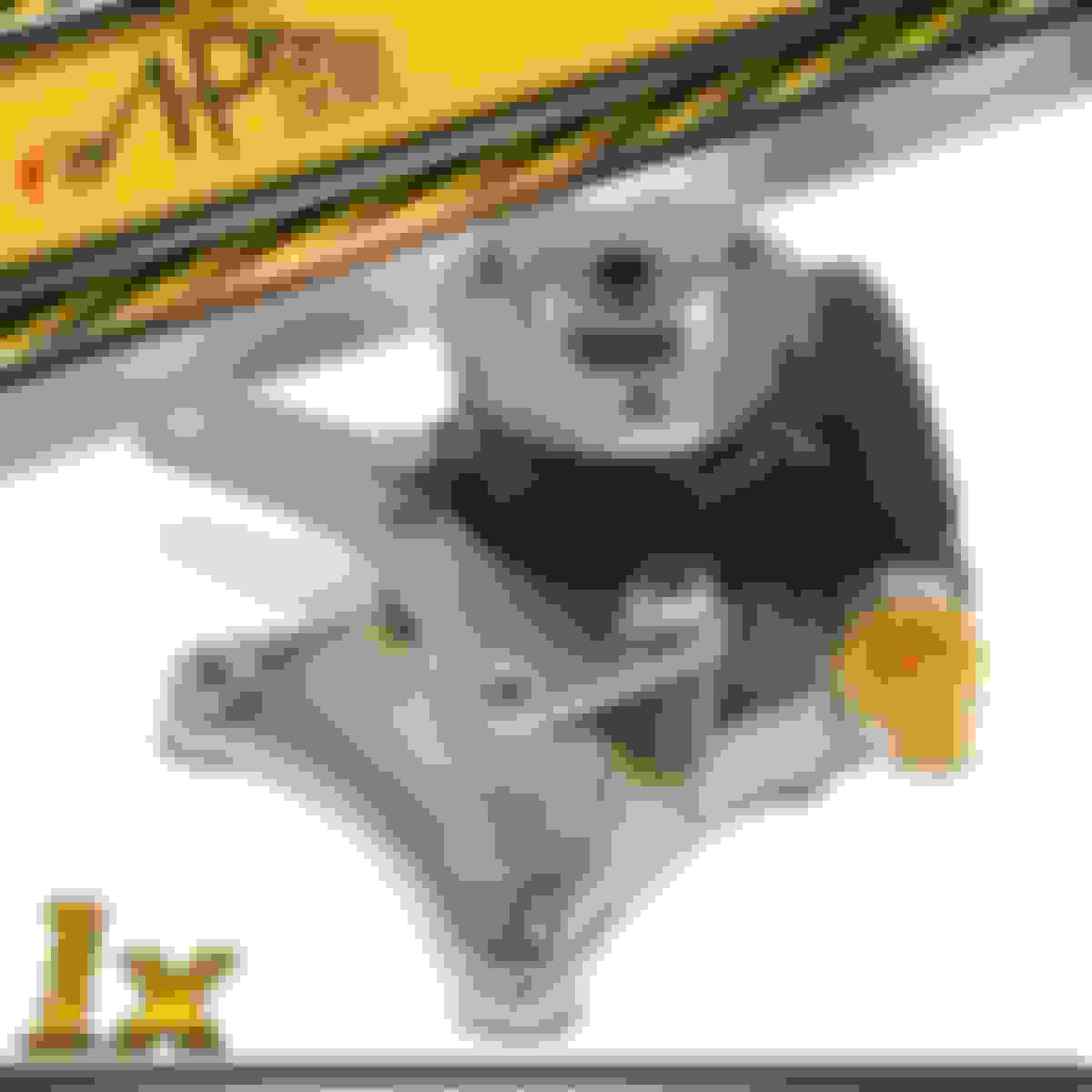
There is a bracket screwed to the front of the pump that you may have to transfer from the old pump to your new one. Some new pumps come with a new bracket already installed. It's easier to remove the pump if you remove those bracket screws, but it adds two more fasteners that you have to remove in an awkward position: Here's a photo of one I grabbed from eBay:
The diagrams above are from parts.jaguarlandroverclassic.com - you can look up parts descriptions there.
I remember doing all the work from above, both by leaning over the left fender/wing but also leaning over the right fender/wing and reaching across the front of the engine. It may be easier to do some of it from below, but I don't remember there being much access from down under. I may be confusing some details with the X308 sedans.
With patience and persistence, I'm confident that you are going to succeed in this job!
It's been awhile since I did an X100 P/S pump but I do remember that the working position is awkward and a lot of the fasteners have to be accessed by feel. I am fortunate to have an inspection endoscope that comes in handy in these situations. An inspection mirror will help also. The oil dipstick tube mounts with one screw through a flange (Part 13 below). Once that screw is removed, you can usually move the tube slightly, or if you want it out of the way, you can pull it up and out of the crankcase. But you'll want to replace the O-ring at the lower end of the tube (Part 12). And reinserting the tube into the crankcase is another blind operation:
The high-pressure hose (Part 13 below) has a rubber section that will give you a little movement once the pump is disconnected. But I find it easier to loosen the high-pressure hose fitting while the pump is still mounted, assuming you can get a flare nut/line wrench on it. Worst case, you can disconnect the hoses at the steering rack end by removing the single screw (Part 17) that secures them, but I can't remember how accessible it is:
It's not absolutely necessary to remove the pump pulley, but it will give you much easier access to the high-pressure hose fitting and help you see the pump mounting bolts. It's much easier to loosen the pulley screws while the accessory drive belt is still installed. Quick, jerking movements of your wrench will be more likely to loosen the pulley screws than slow, gradual pressure, which will be more likely to rotate the pulley. Once the screws are loose, you can remove the belt and then remove the pulley. This diagram shows how the pump and mounting bracket are oriented. There are two mounting bolts for the pump (Part 5), but only one is shown in the diagram. The other one is lower on the same side of the pump (the left side when viewing the pump from the front of the car). The bolts pass through sleeves cast into the mounting bracket (Part 3) and thread into captive nuts on the rear flange of the pump:
There is a bracket screwed to the front of the pump that you may have to transfer from the old pump to your new one. Some new pumps come with a new bracket already installed. It's easier to remove the pump if you remove those bracket screws, but it adds two more fasteners that you have to remove in an awkward position: Here's a photo of one I grabbed from eBay:
The diagrams above are from parts.jaguarlandroverclassic.com - you can look up parts descriptions there.
I remember doing all the work from above, both by leaning over the left fender/wing but also leaning over the right fender/wing and reaching across the front of the engine. It may be easier to do some of it from below, but I don't remember there being much access from down under. I may be confusing some details with the X308 sedans.
With patience and persistence, I'm confident that you are going to succeed in this job!
Cheers,
Don
Much of this helps a lot, but a few things puzzle me.
1- There are only 2 long bolts holding the pump AND front bracket to the block?
2- What are the 90 degree angle bolt holes for bolt #7 and others in the drawing? I don't see those on my pump pics or other drawings. OK, I FIGURED THIS ONE OUT. THAT BIG MOUNTING BRACKET THAT GOES BETWEEN THE EARS ON THE PUMP/BRACKET DOES NOT SHOW UPON ANY OF THE JTIS DRAWINGS FOR THIS R&R. THE 90 degree BOLTS LIKE #7 GO INTO THE HEAD/BLOCK/WHATEVER. That makes some of the pics and parts make more sense.
3- My dipstick tube is not held by that push-in clip like the JTIS drawings show as far as we can feel or see. It appears to be soldered or solidly fixed to that bolted bracket. And, it is NOT up high near the fluid inlet hose connection like the drawing shows. It is vary far down nearer the outlet port of below. Is this accurate and the drawing is crap? Your drawings seem to be better....but how do I know which is correct?
4- But the wiring harness from the Cam Solenoids was clipped to what the drawing showed...but the little plastic clip has been cut in the past. I think I need to pull that wiring harness up out of the way (being very careful of the old wiring)??
5- If the bolt to the dipstick tube bracket cannot be accessed for removal first, how far can I move that tube to get at the bolt if I am sliding the pump/bracket forward?
OH....and what kind of tool does it take to get that HP hose nut and fitting off? I have some brake line box end wrenches, but I don't see how even a small wrench could be maneuvered to get the nut and apply enough torque to break it and re-affix it.
Thanks,
Ken
Last edited by oldjaglover; 03-18-2022 at 01:05 PM.
Much of this helps a lot, but a few things puzzle me.
1- There are only 2 long bolts holding the pump AND front bracket to the block?
The two long bolts hold the pump to the mounting bracket (Part 3 in the exploded diagram of the pump in my previous post). The bracket should not have to be removed. The pump is disconnected from the bracket by removing the long bolts, and if necessary, also loosening the two hex-head screws that secure the pump's front bracket to the pump.
Originally Posted by oldjaglover
What are the 90 degree angle bolt holes for bolt #7 and others in the drawing? I don't see those on my pump pics or other drawings. OK, I FIGURED THIS ONE OUT. THAT BIG MOUNTING BRACKET THAT GOES BETWEEN THE EARS ON THE PUMP/BRACKET DOES NOT SHOW UPON ANY OF THE JTIS DRAWINGS FOR THIS R&R. THE 90 degree BOLTS LIKE #7 GO INTO THE HEAD/BLOCK/WHATEVER. That makes some of the pics and parts make more sense.
Yes.
Originally Posted by oldjaglover
3- My dipstick tube is not held by that push-in clip like the JTIS drawings show as far as we can feel or see. It appears to be soldered or solidly fixed to that bolted bracket. And, it is NOT up high near the fluid inlet hose connection like the drawing shows. It is vary far down nearer the outlet port of below. Is this accurate and the drawing is crap? Your drawings seem to be better....but how do I know which is correct?
See if your pump will come out without disconnecting the dipstick tube at all.
Originally Posted by oldjaglover
But the wiring harness from the Cam Solenoids was clipped to what the drawing showed...but the little plastic clip has been cut in the past. I think I need to pull that wiring harness up out of the way (being very careful of the old wiring)??
Brittle wiring and harnesses are always a problem. See if there are other connection points farther away in each direction that you can disconnect for a little more movement of the harness.
Originally Posted by oldjaglover
5- If the bolt to the dipstick tube bracket cannot be accessed for removal first, how far can I move that tube to get at the bolt if I am sliding the pump/bracket forward?
Again, see if you can get the pump out without disconnecting the dipstick tube at all.
Originally Posted by oldjaglover
OH....and what kind of tool does it take to get that HP hose nut and fitting off? I have some brake line box end wrenches, but I don't see how even a small wrench could be maneuvered to get the nut and apply enough torque to break it and re-affix it.
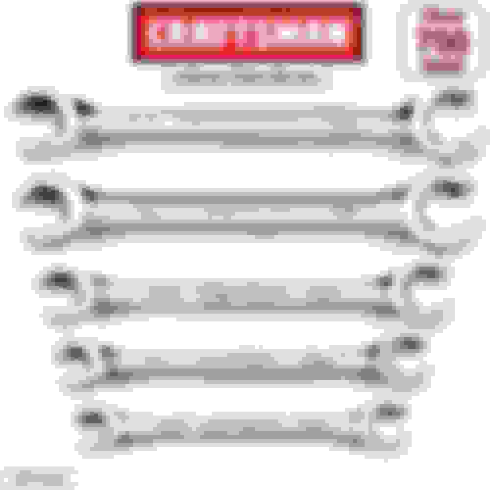
An open-end wrench may work, but you run the risk of rounding the corners of the hex on the pipe fitting, making it even more difficult to loosen and impossible to re-tighten in the new pump. The correct tool is called a flare-nut wrench or hydraulic line wrench, shown in the photo below. As you can see, it's like a 6-point box-end wrench/ring spanner, but there is a gap to permit the jaws to fit around the hydraulic line. The jaws wrap around the hex fitting more fully than a regular open-end wrench, providing extra protection against rounding the hex fitting. Harbor Freight Tools carry these, and your local auto parts stores, Lowes, or Home Depot may also carry them. I think you need a metric set for your X100. Some earlier Jaguars use some SAE/Imperial/Inch-fractional fittings.
The two long bolts hold the pump to the mounting bracket (Part 3 in the exploded diagram of the pump in my previous post). The bracket should not have to be removed. The pump is disconnected from the bracket by removing the long bolts, and if necessary, also loosening the two hex-head screws that secure the pump's front bracket to the pump.
Yes.
See if your pump will come out without disconnecting the dipstick tube at all.
Brittle wiring and harnesses are always a problem. See if there are other connection points farther away in each direction that you can disconnect for a little more movement of the harness.
Again, see if you can get the pump out without disconnecting the dipstick tube at all.
An open-end wrench may work, but you run the risk of rounding the corners of the hex on the pipe fitting, making it even more difficult to loosen and impossible to re-tighten in the new pump. The correct tool is called a flare-nut wrench or hydraulic line wrench, shown in the photo below. As you can see, it's like a 6-point box-end wrench/ring spanner, but there is a gap to permit the jaws to fit around the hydraulic line. The jaws wrap around the hex fitting more fully than a regular open-end wrench, providing extra protection against rounding the hex fitting. Harbor Freight Tools carry these, and your local auto parts stores, Lowes, or Home Depot may also carry them. I think you need a metric set for your X100. Some earlier Jaguars use some SAE/Imperial/Inch-fractional fittings.
Cheers,
Don
I have a set of those wrenches...if we can get them under there. My son managed to detach the wiring harness and move it aside. I don't know why the JTIS drawings show that clip holding the tube. The next step was to secure the tube, so we extracted the small bolt that holds that portion of the cam cover down. Just about a 1/4" to get a small zip tie around both the bolt and the tube. Pulled it tight and it seems to be holding the tube secure for this operation. Lord, I hope we can remember all this when we put her back together. I really should be taking pictures.
My son was able to remove the bolt holding the oil tube bracket to the pump/bracket. We're not sure which it is....rear of pump or main bracket. Anyway, son says the tube appears to be soldered to the bracket.
So, I guess the next step is to loosen the HP line nut. If we can't get to it, is it alright to pull the pump- out some and turn it enough to get at the HP nut??
Thanks again!
Ken
Last edited by oldjaglover; 03-18-2022 at 05:28 PM.
So, I guess the next step is to loosen the HP line nut. If we can't get to it, is it alright to pull the pump- out some and turn it enough to get at the HP nut??
It's usually easier to loosen the HP line fitting with the pump still mounted, if you can get your wrench on it, because otherwise you have to restrain the pump with one hand while levering the wrench with your other hand. With the pump still mounted, the bolts do half of the work for you. Once you have the HP line fitting loosened, you can then remove the pump mounting bolts and you'll hopefully find that you have enough wiggle room to reposition the pump for easier access to fully disconnect the HP line fitting.
It's easier to loosen the HP line fitting with the pump still mounted, if you can get your wrench on it, because otherwise you have to restrain the pump with one hand while levering the wrench with your other hand. With the pump still mounted, the bolts do half of the work for you. Once you have the HP line fitting loosened, you can then remove the pump mounting bolts and you'll hopefully find that you have enough wiggle room to reposition the pump for easier access to fully disconnect the HP line fitting.
Cheers,
Don
We're trying to do it with the pump still fully attached, but can't get any wrench to clear the hard line for the a/c line. My son did manage to get an open end down in there to estimate the size of both nuts since this ridiculous JTIS doesn't give any nut or line sizes. At least not that I've seen. He came up with 16mm or 5/8" for what he thinks is the smaller compression nut. I'm not so sure....think that might be the locking nut which is bigger and thicker.
The other problem here is that he could only get the wrench on at a steep angle. He didn't want to put any pressure on the nut because he didn't want to round the edges. How is the line wrench going to be any different if it also can only grab at an angle??
I had to order a new set of wrenches since the one I did have found is too small (the 3/8" X 7/16" that I used on the ABS brake module). It should be here today sometime. But the question is still about the angle
OH....gotta admit my error on the clip for the HARNESS to the small bracket. I thought the drawing said it was for the oil tube. My bad...they are correct about that.
WE GOT THE NEW SET OF WRENCHES AND THE PROBLEM IS STILL THAT THE CORRECT WRENCH ITS TI A/C LINE.
What the hell am I missing? I see some have gone to great lengths to conjure up crow's feet wrench heads with a shaft that can get past the edge of the pump where it sticks out. This is ridiculous and must be done now since we've got it half apart. I'd sure like to find a video of how this is done.
Ken
Last edited by oldjaglover; 03-22-2022 at 04:58 PM.
We're trying to do it with the pump still fully attached, but can't get any wrench to clear the hard line for the trans cooler. My son did manage to get an open end down in there to estimate the size of both nuts since this ridiculous JTIS doesn't give any nut or line sizes. Art least not that I've seen. He came up with 16mm or 5/8" for what he thinks is the smaller compression nut. I'm not so sure....think that might be the locking nut which is bigger and thicker.
The other problem here is that he could only get the wrench on at a steep angle. He didn't want to put any pressure on the nut because he didn't want to round the edges. How is the line wrench going to be any different if it also can only grab at an angle??
Hi Ken,
Did you remove the pulley from the power steering pump?
Can you disconnect the transmission cooler line brackets and gently move it for better clearance? You can even disconnect it from the radiator if necessary.
P.S. Factory service manuals for most automakers rarely list the sizes of specific fasteners, perhaps due to the extra effort it would require, or perhaps because fastener size can vary during a vehicle's production run.

 11-04-2021, 07:46 AM


 There is the wiring harness for the camshaft solenoid attached right where we need to get at the dipstick and rear of the pump. We disconnected the harness at the clip, but can't move it too far because it seems pretty brittle. Again


 My son managed to detach the wiring harness and move it aside. I don't know why the JTIS drawings show that clip holding the tube. The next step was to secure the tube, so we extracted the small bolt that holds that portion of the cam cover down. Just about a 1/4" to get a small zip tie around both the bolt and the tube. Pulled it tight and it seems to be holding the tube secure for this operation. Lord, I hope we can remember all this when we put her back together. I really should be taking pictures.