When you click on links to various merchants on this site and make a purchase, this can result in this site earning a commission. Affiliate programs and affiliations include, but are not limited to, the eBay Partner Network.
More discussion on Ford & Jag ignitions from Ford Engineer Bob Humphrey
Hi Jim - we just got back from Denise's family reunion in Colorado, so I'm a bit late in responding to emails.
We have three pins on our Ford coils: battery, ground and signal. The coil is dwelled via a 5 volt signal from the PCM, with the pulse duration (duration equals coil dwell time) determined by a look up table in the strategy based on battery voltage and engine coolant temperature. As such it's an "open loop" system. The 12 volt pin is always hot, and conducts current to the primary whenever the 5 volt signal is sent. When the signal goes high, the coil's on board ignitor turns on the IGBT which then conducts current through the ground pin, which is grounded to the cylinder head via the harness. Our diagnostics are pretty basic - the system checks that the current flow through the signal circuit is not less than 3 mA (signal open) or greater than 21 mA (signal shorted). I may be a mA or two off on those figures but they're close. If the system detects a bad coil it will turn off the fuel injectors to prevent raw fuel from damaging the catalyst.
It sounds like the Jag checks the actual primary current, and as such it may be a "closed" system. We'd really need to find out more about how it works. Each cylinder would receive its own pulse (could be a 5 volt pulse like ours), with timing dependent on the speed/load of the engine and the duration dependent on a look up table if it's open loop, or the current sense circuit if it's closed loop. Our older Ford coils were closed loop, with the primary current cut-off driven by a current sense circuit. Has the owner checked all the grounds in the ignition circuit? If there's been significant corrosion build up on any of the grounding points in the primary circuit it would reduce the switch current; it would take quite a bit of corrosion to prevent the primary not hitting 4 amps but it's worth checking. If you find out more about how the system works we can chat at the next meeting. Have a nice evening Jim.
Hi JIm - I responded to your earlier note, but yes for most engines low crank acceleration is how misfire is detected, and as you know misfire could be caused by a number of factors. The crank acceleration of one cylinder is compared to the others, and if it's lower, that cylinder would be ID'd as misfiring. Interesting about the traction giving false misfire readings; hadn't thought about that before.
Regards, Bob
and finally, on the idea of disconnecting coil pins #2 from the ECM to remove the "ignition fail" signal...
Good question. I would assume the ECM (we use a "PCM" for the same purpose) is looking for a high to low to high signal which would require the circuit to be intact, but it would be interesting to try.
Regards, Bob
Is there a way to one by one (OR only for the relevant lines to each coil) bypass the (new) loom and go from the ECU to the coils with something ya made up?
Meaning, identify the signal wires from/to the ECU at the ECU and coils in question, and with a temporary four wire loom that you made up, splice it in between the ECU and the coils, and temporarily remove the new loom sections from the system?
Personally, I think that measurements, readings and meters can get ya so far and confirm but so much, but if continuity readings and right resistance etc etc etc (according to a meter) aren't producing the expected results, something else must be going on.
I'm not sure how I could do this without cutting the wires to bypass. I would be reticent to do that. Then idea sounds good, but man, I think I have enough trouble as it is
Michaelh had mentioned that an oscilloscope would be a good way to see what's happening. I don't have access to one and probably wouldn't know how to use it if I did.
About the osilliscope... I hear ya. I don't have one and wouldn't know how to use one of I did,,, still, then what, even after getting readings...?
I have read only some of this thread but what I thought I remembered was that at some point lots of work, including a new loom for the ignition and gas (FI) was placed and things got a little crazy...? If you look at the wiring diagram and can identify the splice(s) to the coils, although it seems like a ton of wires, it really only boils down to a few. One might also go right from the ECU, create a splice and direct wires to and from each coil. In your case 3 or 4, correct? I will need to go back to the wiring diagram and look... Where did the(se) "new" looms come from on your car? Hand made?
In these forums, especially the XJS forum, people will completely bypass the old loom in the boot and in the foot well of the XJS, go from ECUs and wire directly to coils and resistor pack and etc,,, to troubleshoot these kindsah things. Outside of the car,,, messy style for testing... At the end of the day it's just a little solder and shrink wrap to re-join cut connections.
Me,,, ask anyone here, I would do that no doubt. But that's just me.
In simple terms, what's the problem again. You have 4 injectors not firing because a bad spark and misfire sitch is being detected by the ECU,,, or something like that? Which coils and FIs are in question, if you don't mind...?
About the osilliscope... I hear ya. I don't have one and wouldn't know how to use one of I did,,, still, then what, even after getting readings...?
Hi Jay,
The rationale for this is that it visualises what the ECM is 'seeing' as feedback from the coil packs. If it looks OK (and there is a functioning group of 4 cylinders that is working as it should for comparison) then it's possible to get closer to a diagnosis. However, it's not an option here as johns55 states, so we have to find an alternative route.
Originally Posted by JayJagJay
You have 4 injectors not firing because a bad spark and misfire sitch is being detected by the ECU,,, or something like that? Which coils and FIs are in question, if you don't mind...?
Three out of four cylinders in one group are misbehaving:- two on 'B' bank and one on 'A' bank. This corresponds to the way in which the coil pack confirmation pulses are aggregated and sent back to the ECM.
The car is NOT reporting misfire (P030x codes): as far as we can determine, all the plugs are firing. The ECM is inhibiting the injectors on the failing cylinders, in accord with the thrown P035x codes, to avoid raw fuel being dumped on the catalytic convertors.
Splicing point-to-point is an option, although the looms (both sides of the main engine plug PI1) have been replaced with no change.The coil pack/injector loom came from a 99 hence the divergence in wire colours from the 2000 EG.
Plugs have been replaced and coil packs moved around.
If you can solder, or even if you can't, you can make an oscilloscope out of your phone's speaker port. It is not important to read the scope precisely, you just want to make sure a component is functioning. The main component is a 4 conductor headphones/microphone plug with wires and add 2 resistors. I used approximately 1k & 10k resistors to make a 1:11 voltage divider which just lowers <50V to cell phone level ~5V. Cell phones have much better displays than the basement bargain oscilloscopes and the software is free. I grabbed some funky earbuds, planted the resistors inside the switch case in the middle, soldered some stick pins on in place of the ear buds (two ear bud wires to each pin) and used various shrink tubes to create flexible probes. The pins stick into the tightest crevices . I'm going to say look them up on Youtube for examples to follow rather than me give bad directions. It is fun to play with especially with the phones touch screen- you can raises & lower the screen display vertically to tweak the voltage range and stretch it sideways for closer/wider frquency display, even broaden it to study a single spike. You can add a trigger to freeze a frame. I wish I had more time to mess with it.
I also invested in a siamesed OBD2 cord which made testing very convenient. A plug can be used as convenient breakout board to stick pins into. The CAN & SCP can be viewed in real time on the OBD2 circuit as I recall. For example, you can witness each device on SCP communicating one at a time. With the bonnet open, I could watch engine components respond from inside the cab with the phone on the windshield. I also had my ODB2 tester plugged in so I could read different displays in conjunction with the scope. If you tap into coil pin 2, you ought to compare the "ignition fail" pulses on all 4 coils in that group. Maybe I should give that a try to answer some of my own questions with Bob Humphrey.
I had a serious NO CRANK episode that drove me crazy until I fashioned up my phoneyscope (don't bother Googling that, it is my own coined term) and proved there was absolutely nothing wrong with my XKR, other than it was sabotaged by an unscrupulous key man.
I'm also showing off my "state of the art" Digital VOM! There are times when I prefer an old fashioned D'Arsonval meter.
If you'd like to test drive the oscilloscope before tackling the hardware, download the app AR-Oscilloscope and talk to yourself. "Watch what you say!" It expects the microphone port but will use the phone speaker in lieu of the leads. Pull out the settings hiding on the left hand side and adjust the CH1 to 200mV and the Timebase to 10ms for good response. Check out Youtube for numerous examples.
Hi Jay,
The rationale for this is that it visualises what the ECM is 'seeing' as feedback from the coil packs. If it looks OK (and there is a functioning group of 4 cylinders that is working as it should for comparison) then it's possible to get closer to a diagnosis. However, it's not an option here as johns55 states, so we have to find an alternative route.
Three out of four cylinders in one group are misbehaving:- two on 'B' bank and one on 'A' bank. This corresponds to the way in which the coil pack confirmation pulses are aggregated and sent back to the ECM.
The car is NOT reporting misfire (P030x codes): as far as we can determine, all the plugs are firing. The ECM is inhibiting the injectors on the failing cylinders, in accord with the thrown P035x codes, to avoid raw fuel being dumped on the catalytic convertors.
Splicing point-to-point is an option, although the looms (both sides of the main engine plug PI1) have been replaced with no change.The coil pack/injector loom came from a 99 hence the divergence in wire colours from the 2000 EG.
Plugs have been replaced and coil packs moved around.
Good Morning Michael... All
Good Brotha. Please believe me when I say that I am not in any way trying or wanting to contradict or question your rational here. Actually, I think it's spot on. Thing is, John, as would I, have some limitations when it comes to the approach. No oscilloscope and an inability, or a lack of expertise, in their use...
Me, I'm like Fred Flintstone - y'all know that.
Just to flash back a little. When I was wrestling with my (several) issues on the flooded car, many many members were telling me an oscilloscope would make everything clear and help me solve problems. One member (and I remembered this after saying I had NO oscilloscope) even donated an oscilloscope - an OLDY but a goody. But again, I had no expertise and the learning curve (I think) was greater than the learning curve in working on the original issue/problem. As it turned out, the hardware AND software in more than one of my problems was more a NUTS and BOLTS-ish type problem than they were issues that would be diagnosed with any fine electrical device - kinda. Anywho.
What I think I learned and have been learning is that the systems generally are pretty robust and often it is more a simple-ish mechanical or hardware type of issue or that something was done wrong.
At this point it seems like either on the fire signal, or the report back signal to and from the ECU, the signal is not strong enough, it's being misread, not being sent or received at all or maybe even a combination of all of that. If all of that is happening on only one or two "branchs" of the wiring to and from the ECU (for me - the dude who doesn't know how to use fine electrical monitors) ONE way to eliminate a possible hardware fault (the wiring, damaged, having too much resistance, or too little resistance, or a break) is to temporarily make a new "branch". In my mind I can imagine myself being able to DO it, and UNDO it (2 branches) in 2hrs or so. Y'all know the lead(s) to and from the ECU on both "branches" and you know the leads to and from the individual coil packs. Snip the wire, give yourself room to work with when it comes time to reinstall/rewire, twist in the new "branches" and see what happens. That's just me.
I've been watching this thread a while and y'all have been COOKING. To many cooks in the kitchen (and gooood cooks too!) so I have been reluctant to chime in. I'll go back to being quiet now. Y'all will get this, no doubt.
how is it possible that 3! of the 4! coil packs in one grouping are failing to get or receive signals to the ECU,,, and 1 of the 4 is able to signal correctly? Seems like it should be all or nothing across the group?
What's going on inside of the ECU? Does it detect individual (ok or fail) signals from each plug and coil (and how does it differentiate individual coils from a spliced grouping of wires?) or does it detect the entire group as a bunch and work with that info?
If it's working in groups of coils spliced together providing one signal for ok to fuel or not ok to fuel,,, can an amperage drop (or misreading) in one or two coils affect the whole group? I mean, it's one wire that eventually makes it to the ECU for monitoring right,,, so if one is misreading does it throw everything off in the "group"?
Is this the version of the ED y'all are looking at?
This is from the 2000 ED.
What I think I learned and have been learning is that the systems generally are pretty robust and often it is more a simple-ish mechanical or hardware type of issue or that something was done wrong.
Totally agree - Occam's razor and all that, but johns55 has gone systematically through the wiring, coil packs and plugs. etc. and the codes don't change.
Originally Posted by JayJagJay
...how is it possible that 3! of the 4! coil packs in one grouping are failing to get or receive signals to the ECU,,, and 1 of the 4 is able to signal correctly? Seems like it should be all or nothing across the group?
The $64 question. I can't explain that at the moment. Three out of four failing at the same time tends to lead me away from the coil packs, particularly since they have been swopped around, but it's not definitive. That is why it would be useful to see what's going back to the ECM on that channel.
Originally Posted by JayJagJay
What's going on inside of the ECU? Does it detect individual (ok or fail) signals from each plug and coil (and how does it differentiate individual coils from a spliced grouping of wires?) or does it detect the entire group as a bunch and work with that info?
The ECM detects each individual confirmation pulse. It can work out which cylinder the pulse relates to as it knows where the crankshaft cycle is at any point in time.
The confirmation feedback for all eight cylinders could in theory either be sent along the same piece of wire, or on separate wires. Grouping the feedback into two lots of four - and including two from each bank - is a compromise between the amount of wiring and providing a diversity so there's not a single point of failure, IMO.
Originally Posted by JayJagJay
If it's working in groups of coils spliced together providing one signal for ok to fuel or not ok to fuel,,, can an amperage drop (or misreading) in one or two coils affect the whole group? I mean, it's one wire that eventually makes it to the ECU for monitoring right,,, so if one is misreading does it throw everything off in the "group"?
Is this the version of the ED y'all are looking at?
This is from the 2000 ED.
I imagine that an internal short in one coil pack feedback circuit would bring the whole line down, so none of the cylinders in the group would be fuelled. I guess it's possible a low resistance on one could pull the line down enough so that only the signal from one pack 'made it through', but that's purely conjecture on my part. Moving coils around tends to discount this, though.
Maybe it's the ECM that isn't driving those three coils hard enough? At this stage, I can't say.
The snip I attached in an earlier post is from the 99 EG, as johns55 changed the looms. The wiring is the same, just Jaguar changed the wire colours between 99 and 2000.
edit: Please feel free to challenge:- it helps keep me honest
I'll break this down in three segments, first is setup and quick glimpse at display, second will focus on the coil pin 2 "ignition fail" and third will show pins 3 & 4 for "trigger pulse" and the 12V feed. Coil pin 1 is ground and doesn't show any activity.
I didn't need the hemostat for the scope. It is bad enough I dropped a small socket while removing coil cover, but my flashlight lost the ring and lens so I had to do some fishing.
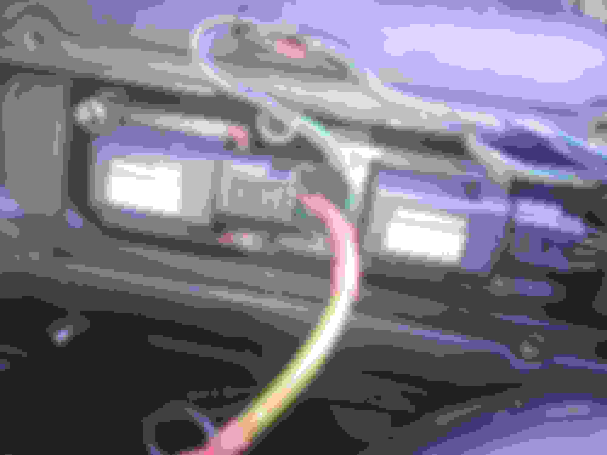
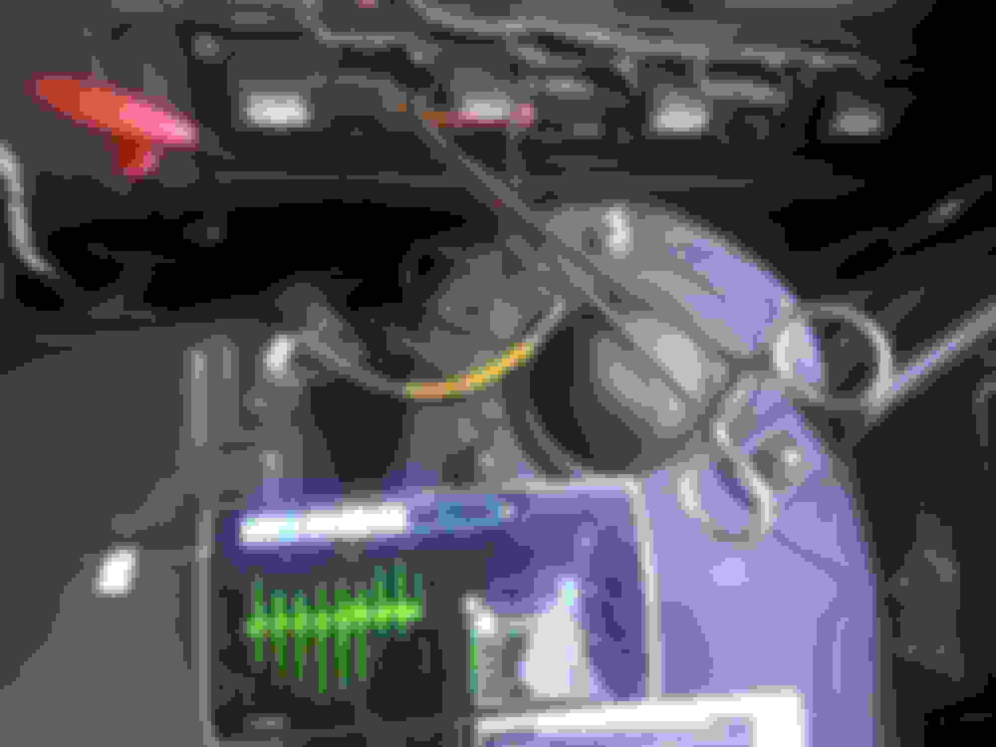
Cell phone-oscilloscope displaying 12V coil feed , with yellow lead above it grounded and hemostat hooked to lead on coil pin 4, purple white 12V feed. "stick pin" probe in coil pin 2 with "slate light green" wire for "ignition fail" ground probe pin stuck to ground with magnet
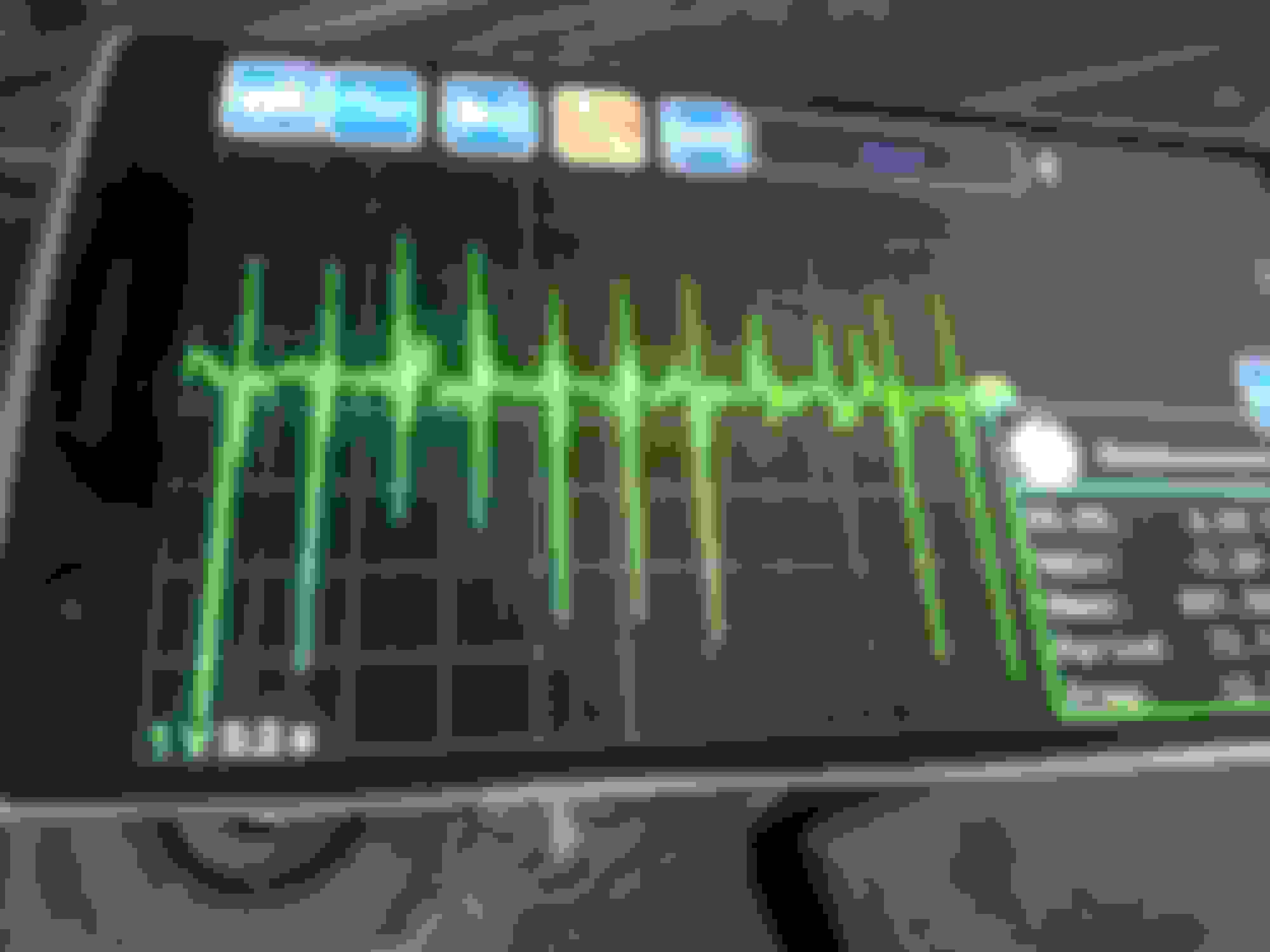
The display for pin 2 shows it runs a bias voltage normally. When the ECM initiates a spark, coil pin 2 spikes high and when the primary amperage exceeds 2 amps and hits 4 amps, the signal drop low, negative to the bias voltage level. If the ignition module doesn't send the negative signal, the ECM interprets it as a misfire. I'm betting that the signals in this image are for 4 coils consecutively.
With the sun setting behind me, I had to deal with shadows, reflections on the camera face and a flash reflection obliterating the pictures. I failed to capture the measurements on the phone. That really isn't critical as it is the image we're looking at for discrepancies between coils. coil pin 2 confirming good ignition, likely for 4 coils in a group.
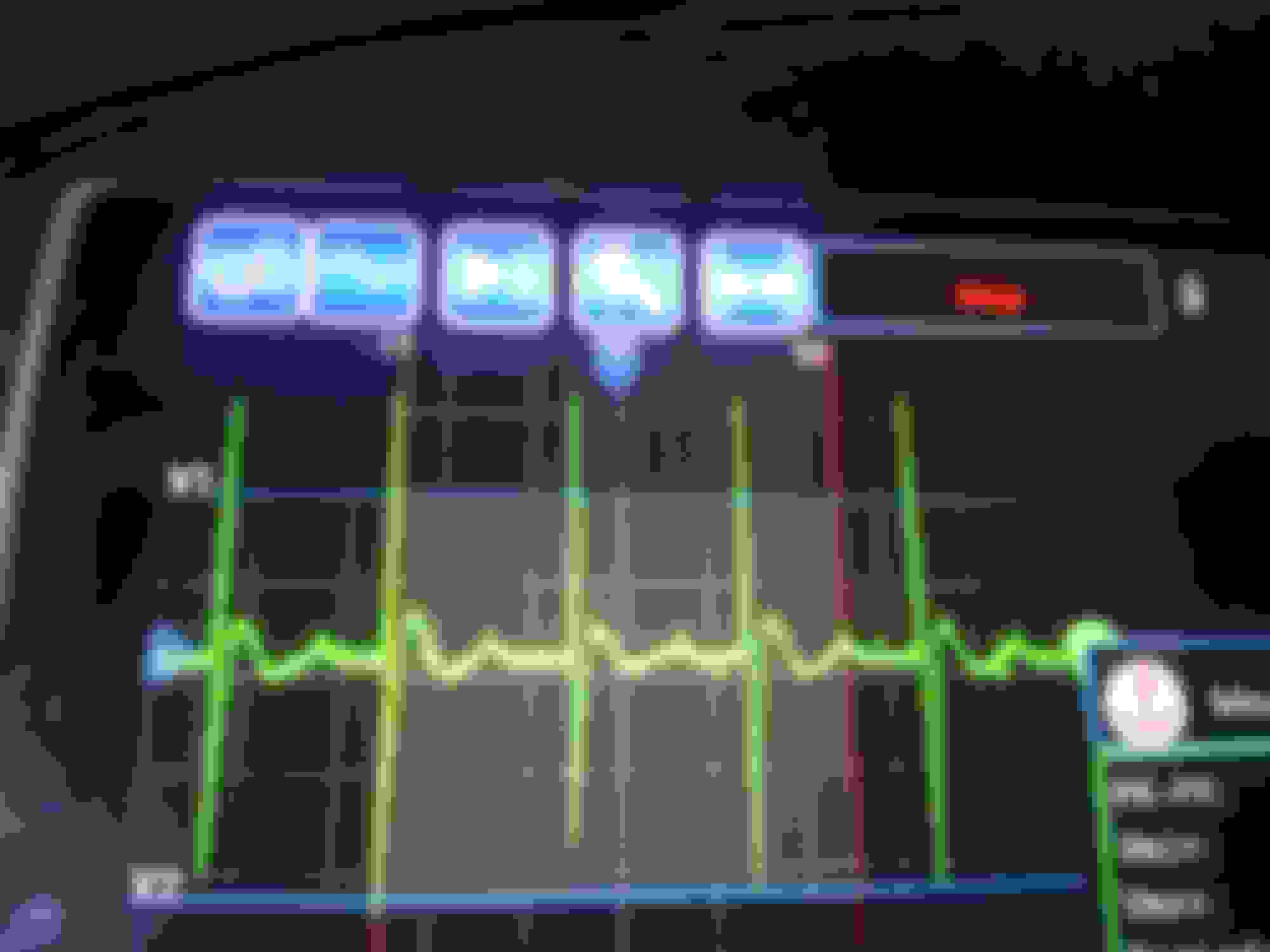
The first three pictures are for pin 3 and the last one for pin 4.
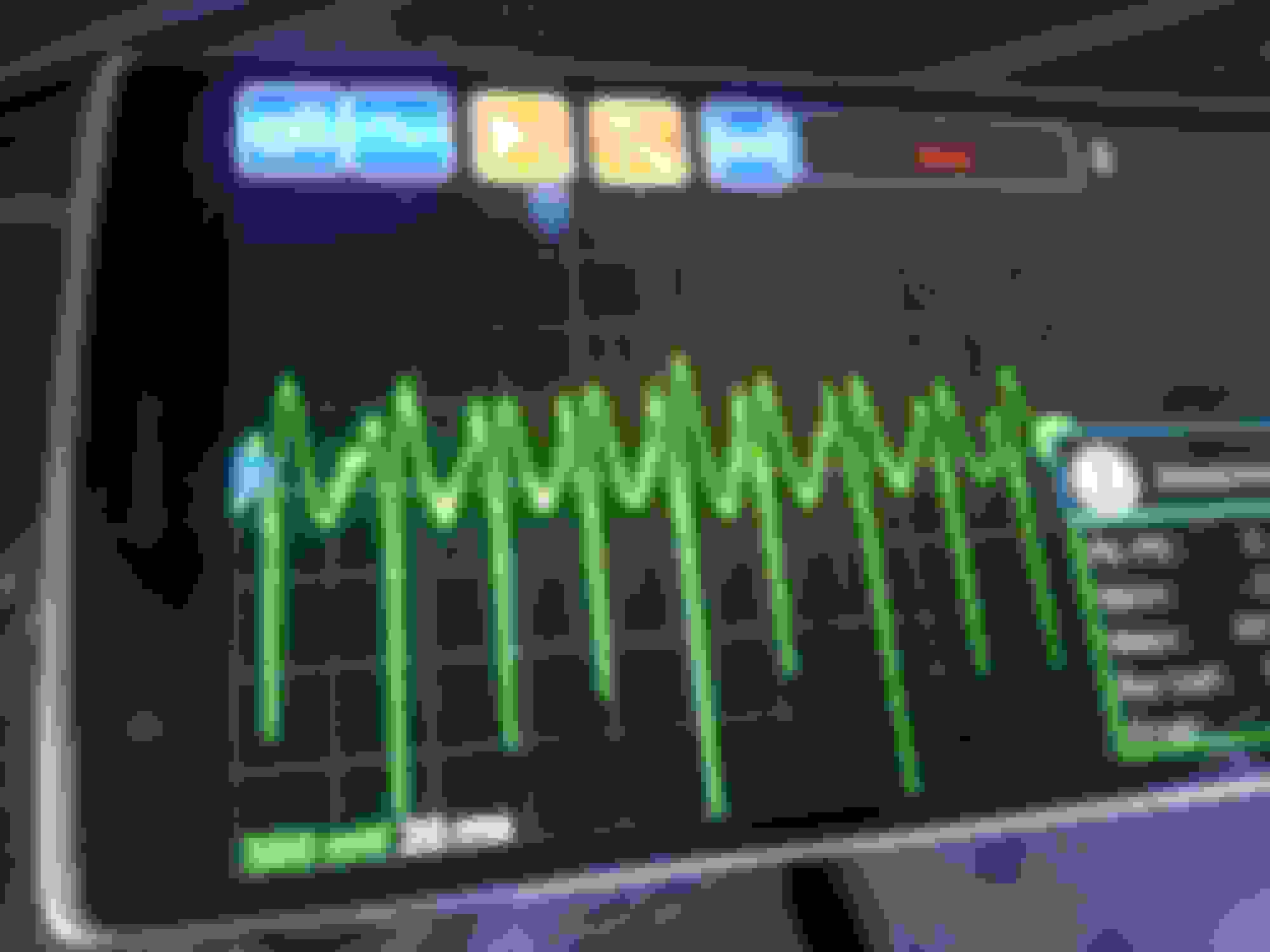
Coil pin 3 is the trigger for the coil from the ECM. The phone display would represent only the one coil connected. The pulses are regularly spaced for a smooth idle, but it is interesting how the pulses shift high and then low.
Coil pin 4 is the positive 12V feed from the relay. It would be representative for all 8 cylinders. The voltage drops, must indicate each coil firing. If there were descending spikes missing periodically, it could indicate an open coil.
pin 3, ignition trigger from ECM pin 3 again. note the measurements displayed. This software is priceless, really, $0. purple white wire, pin 4
The first three pictures are for pin 3 and the last one for pin 4.
Coil pin 3 is the trigger for the coil from the ECM. The phone display would represent only the one coil connected. The pulses are regularly spaced for a smooth idle, but it is interesting how the pulses shift high and then low.
Coil pin 4 is the positive 12V feed from the relay. It would be representative for all 8 cylinders. The voltage drops, must indicate each coil firing. If there were descending spikes missing periodically, it could indicate an open coil.
pin 3, ignition trigger from ECM pin 3 again. note the measurements displayed. This software is priceless, really, $0. purple white wire, pin 4
Damn! That's a NICE post right there. And good info!
So, if the gentleman connects an osilliscope,,, and see's different information than this, then what? Connectors, plugs, wiring, coils, ECU,,, what? Not trying to be a wise ***, just wondering...
There is concern the "coil fail" signal from the coil ignition module is feeding back to the ECM, the coil is misfiring, whether it be true or erroneous. After clearing the codes and restarting the engine, we'd be able to see if the coil signals at pin 2 are really missing the negative spike and misfiring is from coil feedback or not. If so, why. The ignition fail feedback is based on the primary side of the coil. Maybe the ground wires have high resistance on the group of four coils. Could it be low compression where the coil can't fully discharge the magnetic flux and will not draw the primary amperage next fire? Maybe smaller plug gap could compensate. Maybe the misfiring has nothing to do with the ignition but everything to do with the crank velocity showing weak cylinders. When I was playing around with the coils, I'd again noticed some of the iron cores were rustier than others. The coil-on-plug schematic shows the coil is grounded on black wire #1 and does not indicate any other ground. If the coils do rely on the iron frame for grounding to the aluminum head, it is possible corrosion between dissimilar metals could be a factor. You'd think swapping in new coils would have negated that problem, but iron is more noble that aluminum and aluminum loves to cover itself in aluminum oxide, an insulator, with or without a galvanic cell situation.
Pin 3 shows the handshake between the ECM and ignition module trigger. This is not the primary current but a weak signal for the ignition module to ground the coil primary. If there were gaps of missing pulses, we might point fingers at the ECM for not calling for spark for whatever reason. We know it curtails injector activity, but I'm not aware of any reason the ECM would intentionally hold off firing plugs.
Pin 4 shows the periodic reaction of the 12V feed to coils firing. Bob Humphrey mentioned at his ignition talk at our MG Club meeting something I've never seen in print, that a good coil should be able to produce its spark in 17 millionths of a second. Those negative spikes are very brief and maybe represent the dwell time. Missing pulses here would go along with coils failing to draw primary current. Someone might also spend some time trying to measure the time between each spark precisely enough to see if there is any detectable unevenness that the ECM is looking at that is misinterpreted as misfiring. Maybe someone might look at the measurements and discover "we don't have 12V feeding the coils!!! Where'd it go???" Now I wish I'd have included the measurements in the last image for reference, but taking pictures was just "point and click" at the time. I suspect the voltages displayed aren't the true voltages anyway since the oscilloscope is working through resistors forming a voltage divider to reduce the V to a fraction of actual. I need to give that some thought.
From the looks of the images and literature on the system, I'm concluding the ignition is single fire only, not multifire like some others.
Thanks for the pictures, Jim. They do help to visualise the various signals between the ECM and coil packs on a healthy engine. I agree that the calibration is adrift, but it's of no consequence here as we only need to compare pulse amplitude with the known good.
IMO it's erroneous to refer to the issue as a misfire. The car isn't reporting that: - the lack of combustion in the failing cylinders (and the consequential peturbations in crank angular speed that could indicate a misfire) is intentional to avoid cat damage. It is true that the 'possible causes' for the p030x codes are very similar to those for P035x, yet the ECM reports the latter.
Back in February, post #46, "ECM codes that came back after clearing all codes was still P0353, P0355, P0358." There may or may not be a misfire, but the ECM looks at data and reports its own conclusions. If it hasn't had a P035X error in months, maybe the old faults were just transient errors.
I do recall the low compression readings but they were clustered close together. I bought my wife a '58 ****** for Mother's Day with a Ford 260 V8. My old compression tester has a Shrader valves issue so I bought a new Chinese kit very cheap. The old gauge showed readings in the 180s, which made me very happy. The new compression gauge came back with 140s across the board. Got what I paid for? Often, it isn't the quantity of compression, but the quality of the group. The Jaguar readings were close clustered but still low. I've had experiences with Hondas that have seriously overheated, lost some compression and the rings yielded so bad, I could roll the short block over with one hand (sans head).
The factory plug gap has been reported at 0.051" which isn't bad for a new Jaguar but may be fairly generous for old cats. I recall 0.070" for GM HEI ignitions decades ago. That may have been wishful thinking after the miles piled on. I'd use extreme care with platinum or iridium plugs and close up a handful of plugs to more like 0.035" and see what happens.
You're right, that elephant is still in the room..."the lack of combustion in the failing cylinders (and the consequential peturbations in crank angular speed that could indicate a misfire)".
I think we're all looking for the same needle in the haystack- why is the ECM shutting down injectors. A fire breathing cat roars around one minute and then is a weak as a kitten the next, makes a miraculous recovery for no reason, then is back on its deathbed.... we're missing something in the Jaguar's jungle.
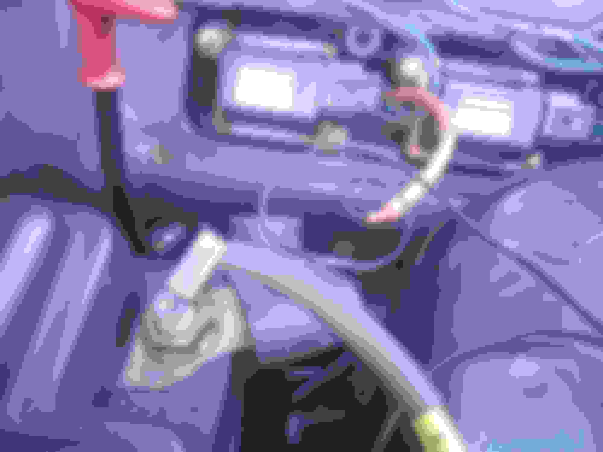
I think the pin on the scope held with a magnet (photo above) is "stuck" to a 12v positive on the LH fuse box in the photo...? Is that the bolt and nutt in the photo, or am I mis-seeing?
Me,,, I think this all could boil down to bad wiring.
I think it's possible that right running could be had with making up a temporary "loom" for the feedback set or the trigger set of wires wired directly from the ECU to the individual (3) coils in question... Just do all 4... It would take 2 hours (or less) to do. After all this time, what's to lose?
I promise I'm not trying, wanting to or picking a fight with y'all... I respect y'all's expertise... And I ain't just saying that.
Then, Possibly a bad batch of plugs?
Poorly gapped plugs?
A connector problem on one of the coils?
Something like that.
That's just me.
I hadn't driven one of my cars for several weeks. 02 xk with the 00 engine. Went to start it yesterday and had a dead battery. 11.1v. "reconditioned" it overnight... To 12.8v... Put it in the car this morning to find a c1175 code and a p0020 p0021 codes... Drove the car. c1175 disappeared (as did abs light) but remained on the OBD for part of day as pending.... P0020 and 21 remained. CEL on. Cleared the codes and they never came back.
Drove my 04 XKR back and forth to and thru Vermont over the weekend. Alllll up and down mountain sides. Out of nowhere,,, had a p1624 (I think it was) for no reason I can think of... Disappeared on the way home from Vt...
Point is these are tricky cars and relying strictly on readings, measurements and expected values isn't always the answer. They have a way to them and a mind of their own sometimes.
So, I'm not going to go back and read everything trying to find answers to all my questions or whether or not the things I'm thinking have been tried or looked at already... There's just too much... If anything I mention has been dealt with tell me to zip it and carry on...
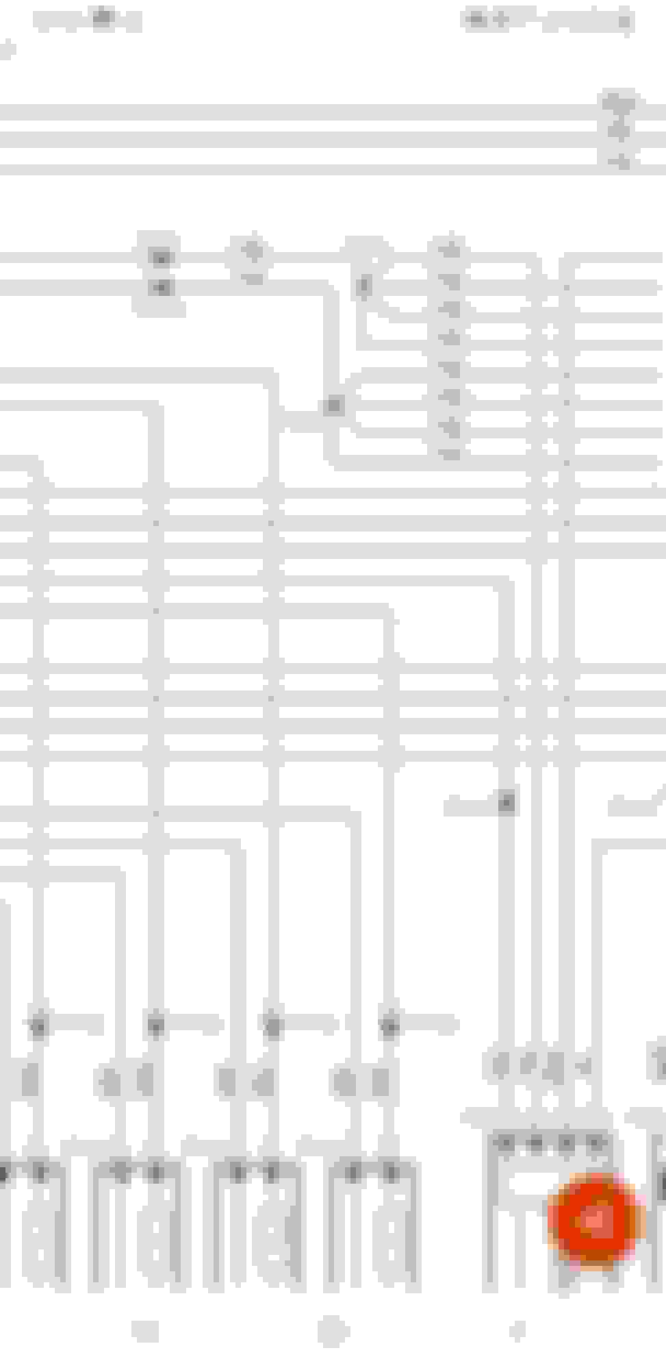
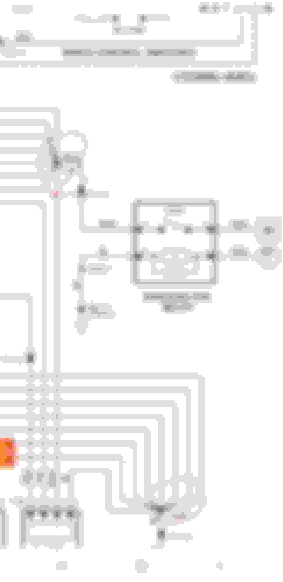
Here's one thing I'm looking at. In the attached photo, the way Jaguar describes things in the ED is that at PIS11 and PIS12 there is ONE main hard wire YG that comes off the ECU and the remaining 6 YG wires are spliced off of them. >>>> When I have found splices on these cars I have been amazed at how what's in the ED actually LOOKS like the actual physical splice... At PIS12 and PIS11, both "mains" go to cylinders 4A and 4B respectively...
Q: do the coil/injector disfunctions on those 3 cylinders correspond with the 3 NON mains off of one of those splices at all? If the person who removed the replacement harness got frustrated and yanked on the wiring at all,,, you know what I'm getting at. Or if the parts car sat in the rain and water got into the splice (which could be a possibility for several of the MAJOR splice locations) there could be issues...
Another, looking at the ED, has the condition of the splices circled in red below been specifically examined and looked at for damage? I'll add this >>> I can't tell ya how many times I have gotten spark on spark plugs,,, continuity on a wire set, or "right" resistance values just to find when LOOKING at/handling the thing, something clearly wasn't right. cracked tip on an injector (XJS and Porsche),,, main power cable from mega fuse in boot to in cabin fuse boxes (Xk8),,, multiple abs sensors (especially on the Porsche and Xk8),,, fuel injector harness (especially on the XJS),,,, especially on plugs and coils (especially on the XJS),,, TPS (especially on the XJS),,, and last (not really) but not least O2 sensors on all these damn machines... All these examples tested well with a device,,, but DIDNT operate correctly for REAL service.
Then,,, the PI1xx 57 pin connector on top of the transmission... Has that been properly eyeballed, cleaned up, dealt with? There are coolant hoses over the PI1 that feed the TB. If anyone of the coolant hoses ever leaked, even if it was 12yrs ago (on the old loom or the "new"), there could be issues. If the parts car sat outside with the hood opened or partly opened - just saying... I think I remember other strange codes waaaay at the beginning of this thread, or the other one, that couldn't be explained AND had dealings with the PI1xx box on top of the trans.
Because a coil and plug are sparking doesn't mean its giving enough BANG... That's another thing.
 06-27-2022, 11:25 PM