When you click on links to various merchants on this site and make a purchase, this can result in this site earning a commission. Affiliate programs and affiliations include, but are not limited to, the eBay Partner Network.
1997 XK8 convertible. Approx 117K miles. Have had the dreaded intermittent ABS light and suspension fail lights for a few years. Rarely driven, I never fixed it because it would go off and I'd forget about it.
So, after scouring all the threads I could find about the R&R and repair of this problem, I dove in. My experience will be documented here with pics because it's not as simple as it sounds, or as some technical pros make it look in their pics. PLUS....not all cars and models are the same.
I started by pulling the cover on the left front fender fuse box. There are 3 fuses designated for the ABS system. Because I did not want to disconnect the battery and restart my emissions system computer, I pulled the fuses that serve the module and pump. That would be #16 and #18 on the left side, and #4 on the right side. In my car, there were yellow covers on each of the ABS fuses. I have no idea why. I will post pics as soon as I figure out how to get them from my phone to this forum. Break here.
Apparently, HEIC files from Apple iphones cannot be uploaded even after being opened in W10 and easily viewed on my laptop. WTH! I need to show you what I encountered, but cannot load pics. GRRR!
I removed mine and resoldered the bad joints without removing power or fuses. I just unplugged the module and bent the lines out of the way (NO FUN!).
Putting it back in wasn’t that easy either. I made a plastic cover to cover and protect the pins from being bent while putting the module back through the lines.
OK. Here's the inside of my fuse box and some other key components to deal with. Just for safety sake I removed the 3 "covered" ABS fuses. Why only those had the yellow covers on them I don't know. You can also see the blue-topped washer fill tube that seldom gets mentioned. It has to be grabbed firmly, twisted and removed. Other obstacles are the mounting brackets for the power steering reservoir, the bracket for the plastic cover/shield for the entire module/pump assembly, and any other bits or brackets that will bruise your knuckles and dig into your arms. ADD an hour to get all this stuff out of the way. Take your time. You will also notice that my brake lines are really, really close to my module, and that my configuration is different from the normal pics and videos.
Last edited by oldjaglover; 08-29-2021 at 04:03 PM.
Reason: add text
Now, hopefully, a view with the two brake lines detached and the module removed. Removing the 4 long bolts is standard procedure. I did mine with a 1/8 socket tool and a 5/32 socket (matches the metric reverse torx head). In my case, the 2 brake lines came out easily and bent easily out of the way AFTER ALL THE CLIPS WERE REMOVED. The connection on the lower left was so tight I couldn't budge it, so I moved the line gently to the left out of the way. Disconnecting the bigger wiring clip, plug, and harness was fairly easy when you keep puling up on the release "clip". It come up about an inch. The wiring plug to the actual "offending" solder joints inside the module was really....REALLY....hard for me. I could not get my fingers down in there to release the clips from both sides, so I mangled them with a large set of needle nose pliers. NOT the way to do it, I'm sure. Let's try showing you a pic: Nope. The email I used to send a pic to myself will not repeat the function. Sorry. Hope I haven't wasted your time.
Below is one of the backside of the module where the power steering bracket bolts on (actually held by two 10mm nuts). This bracket needs to be loosened or removed to move the module away from the brake lines.
Last edited by oldjaglover; 08-30-2021 at 04:32 PM.
I removed mine and resoldered the bad joints without removing power or fuses. I just unplugged the module and bent the lines out of the way (NO FUN!).
Putting it back in wasn�t that easy either. I made a plastic cover to cover and protect the pins from being bent while putting the module back through the lines.
What method did you use to separate the module top to get at the solder joints?
Use a hacksaw or dremel, but go carefully as you don't want to cut into anything inside. You are fairly safe on the longer edges of the module as the ferrules will stop you cutting too deep with the hacksaw.
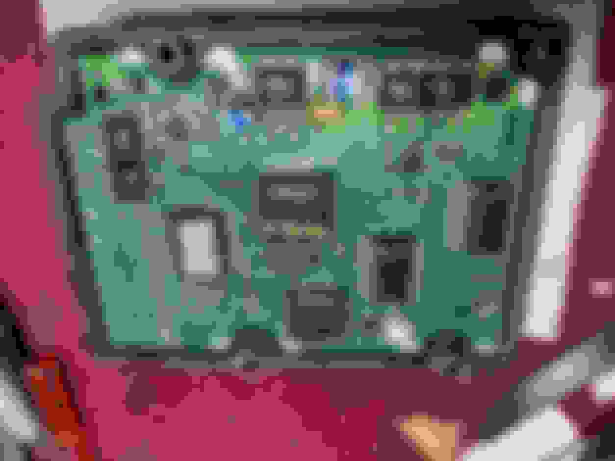
Here's the backside of the module and PS reservoir bracket. Reach down and remove the two 10mm nuts. The upper bracket hole is from the cover that was removed to get to the module at the beginning. T resized this down by 50%, but it's still huge. Sorry. I ALSO removed the small coolant line with the weird clips that don't want to release. It can be pulled off with a firm tug, and a tiny bit of coolant may come out.
Last edited by oldjaglover; 08-30-2021 at 02:42 PM.
Reason: text
Apparently, HEIC files from Apple iphones cannot be uploaded even after being opened in W10 and easily viewed on my laptop. WTH! I need to show you what I encountered, but cannot load pics. GRRR!
Between this cumbersome forum method of loading pics and the nightmare iphone has created with their HEIC format, I have solved the problem, but it takes a lot of time. I still want to load some pics that are not shown in some of the other tutorials. So....more should load here: Still too big. Notice where the windshield washer fill tube and blue cap has been removed. Also, you can see how the brake lines were right up against the module case on my car, thereby making it impossible to just "slip" it out from under the lines without removing some of them.
Here's what it looks like with 2 of the brake lines removed to get the module out. I only had a few drops of brake fluid from those lines. I was able to wiggle the module out after disconnecting the larger multi-pin connector by pulling up on the "clip". Fairly easy. But the second wire plug, the 2-prong one that is connected to the solder joints we need to get at, was extremely hard to get at and unclip on MY car. I have no idea if others are buried down under the right side of the module like mine was.
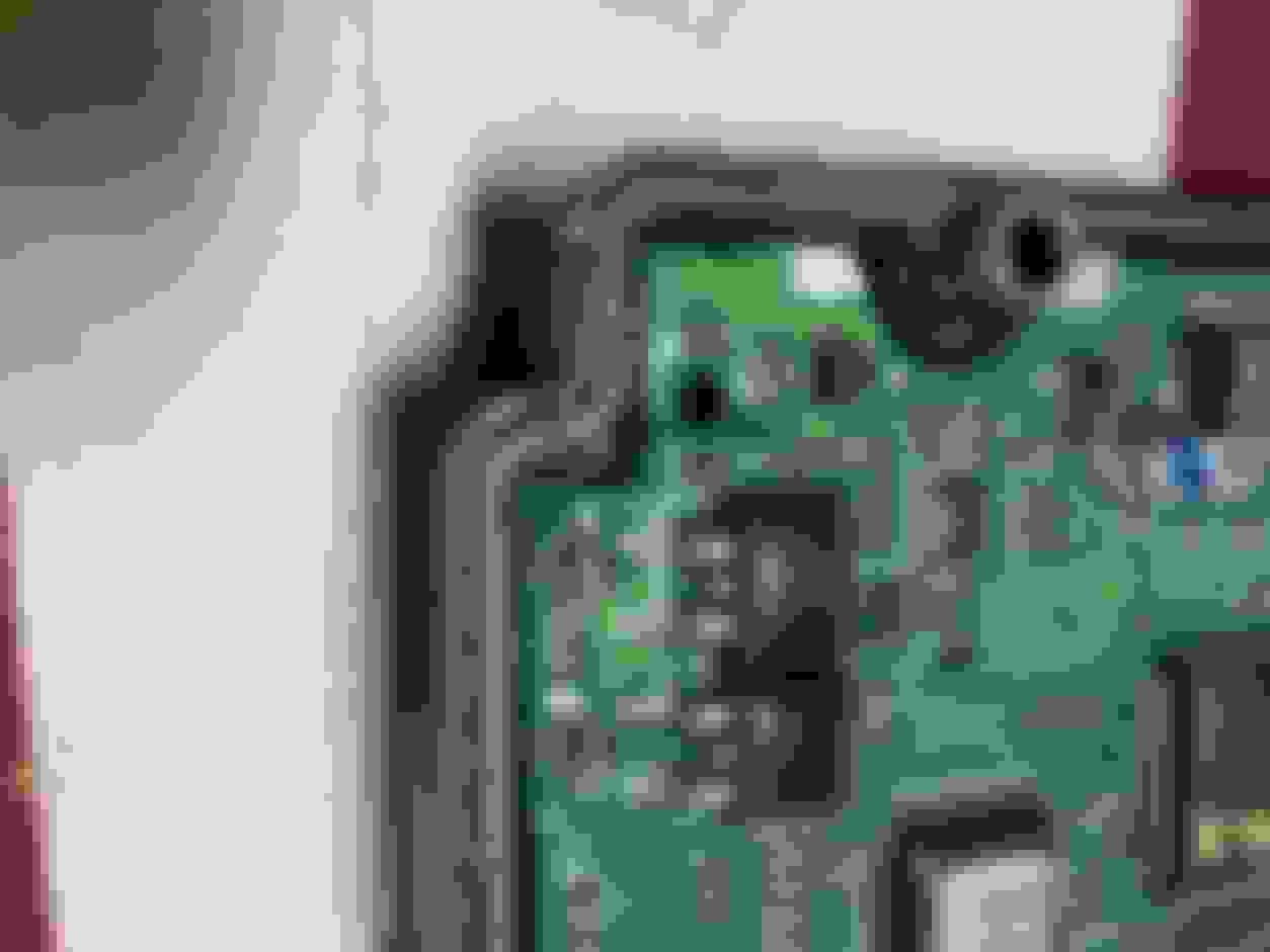
Next I wanted to show you what the second smaller plug and wiring looks like from down in there. I had to mangle the side clips just to get the darn thing out because it was so far down in and facing a bad angle. You can also see how short the wiring is, making it hard to get up to work with it. In fact, I do not like the looks of those 2 wires.
Next, the box needs to be opened or drilled. I think I am going to open the whole thing, and we have members who have used hacksaw blades or razor saws to do it. I have both, so I will follow the groove and see what I can do. Here's the box: As you can see, there is a very nice groove all the way around the box. It should be easy to separate...right? We'll see.
All things considered, this repair is not hellish. Just a little frustrating. There are many issues with these
cars that are much more time and dollar consuming. I�ll take this job hands down over any repair that involves opening my wallet. The R&R and soldering can be done in less
than one day for zero $$$
Z
Yes, compared to replacing the cam chain tensioners and related parts and pieces; upgrading the brakes, replacing the front shocks, top mounts, all the rubber bushings up front; replacing the rear speakers; replacing the "combination switch"; replacing the door lock rods; replacing the water pump, water tower, hoses, and gaskets; and more I hate to even think of......repairing this ABS module is easier. It's just made harder than it should be by a ridiculous amount of brackets and hand-cutting, knuckle-busting screws, bolts, nuts, clamps, clips, and covers. And, I still have to cut open the case, re-solder the connections, re-seal the module, and get it all back in and buttoned up. It's such a bitch with arthritis and not-so-good eyesight anymore. Methinks these Jags are a pleasure for old men to drive , but a younger man's car to work on.
yes, The only time having the XK makes me feel less than 70, with all the maladies that falling off motorcycles 50 years ago bring, is when I’m driving it.
No modern car I’ve seen was made with consideration of the mechanic, and darned few classics.
....It's just made harder than it should be by a ridiculous amount of brackets and hand-cutting, knuckle-busting screws, bolts, nuts, clamps, clips, and covers. And, I still have to cut open the case, re-solder the connections, re-seal the module, and get it ....
Are you suggesting the ABS and other modules should not be encased but simply thrown in with the engine and the lid closed so it is easier to fetch them out for repair.?
l always thought there was a purpose to brackets and bolts etc.
If this was my '66 Ford Fairlane it would be easy, but when you want all that stuff in a small space with a shape like an X100, there's a price to pay in ease of maintenance and repair. At least you don't need to drop the engine out the bottom to change the spark plugs !
I decided to use a razor saw and cut all around the sides to remove the circuit board and expose the offending solder joints. Not so bad as my saw ia very sharp and cuts through the ABS plastic easily. As has been said, don't try to cut through the steel bolt shafts/chambers, or whatever they are called. The plastic case sealing is NOT dependent on going around those tubes. They have some small clips on the underside to hold them even tighter to the whole case. BUT WHAT YOU WILL ENCOUNTER....and has not been mentioned to my observation....are the 4 ring clips that ARE actually holding the top half to the bottom half like a vice. Pics in a second. I tried removing the clips when I saw that no amount of cutting or wedging was going to release them, but nothing worked. SO I WEDGED HARDER RIGHT NEXT TO THE STEEL TUBES. With a thicker wedge, each one flew off like a rocket. Use a rag to keep them from being lost forever. I recovered all 4 of mine.
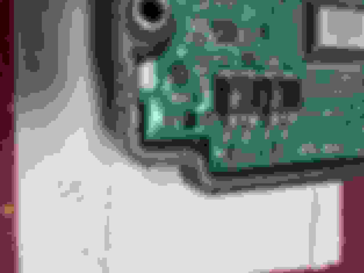
Next, of course was the inspection of the circuit board. I was shocked (in both a good way and a bad way) to find that mine is coated in a thick clear protective plastic film. GOOD because the board is really sealed tight and clean. BAD because my critical solder joints to the ABS pump are also sealed and look very clean and well-preserved. Uh oh! Pics will tell: I looked closely at the solder joints under several magnifiers, then sent the pics to my brother who is an electrical engineer specializing in building giant antennas and related equipment. Neither of us could see any cracking or dry solder failure. Again....UH OH! If you go back to the pic of the pump wire leads to the plug that goes into the board.....I wonder. The wires are very short and tight. I'll have to do continuity tests, but the problem was intermittent so that mightb not show up.
You can see the plastic coating by the reflection. I dusted it a little better for these.
Last edited by oldjaglover; 08-31-2021 at 03:26 PM.
Reason: info

 08-27-2021, 07:14 PM


 I need to show you what I encountered, but cannot load pics. GRRR!