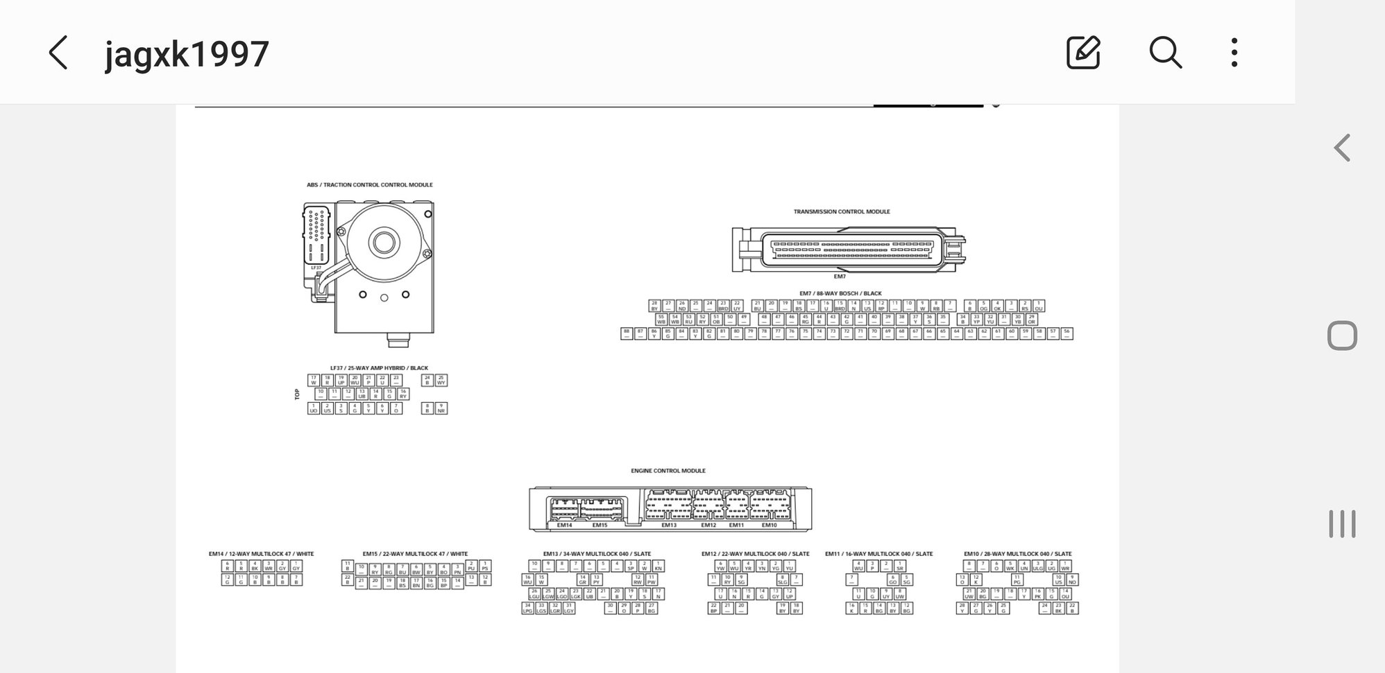
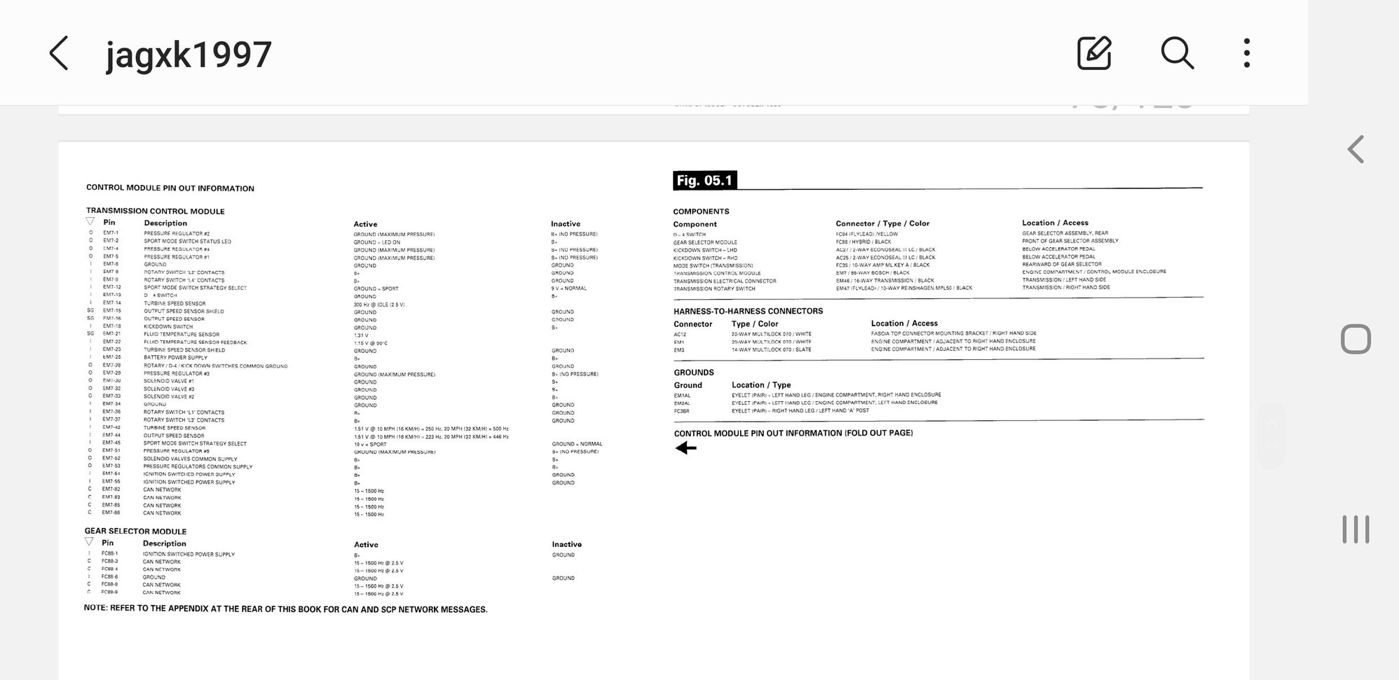
TCM pinouts
#1
Hello all,
I am in the process of tracking down an engine fault, and one of the items mentioned by a couple members was the rotary switch P/N connection, which I've traced to white/red & green, continuity needed for a start.
The harness is quite difficult to reach, and I'm a bit worried about fat-fingering things down in the rear behind the engine. Before I take that risk, does anyone know if there is a chart somewhere of the TCM pinouts? I'd much rather test the wires at that plug rather than reaching behind the throttle body if possible.
If not, I will take a crack at it, just a bit nervous with all the brittle clips and whatnot back there.
Thanks!
-Jim
#2
Hello all,
I am in the process of tracking down an engine fault, and one of the items mentioned by a couple members was the rotary switch P/N connection, which I've traced to white/red & green, continuity needed for a start.
The harness is quite difficult to reach, and I'm a bit worried about fat-fingering things down in the rear behind the engine. Before I take that risk, does anyone know if there is a chart somewhere of the TCM pinouts? I'd much rather test the wires at that plug rather than reaching behind the throttle body if possible.
If not, I will take a crack at it, just a bit nervous with all the brittle clips and whatnot back there.
Thanks!
-Jim
I am in the process of tracking down an engine fault, and one of the items mentioned by a couple members was the rotary switch P/N connection, which I've traced to white/red & green, continuity needed for a start.
The harness is quite difficult to reach, and I'm a bit worried about fat-fingering things down in the rear behind the engine. Before I take that risk, does anyone know if there is a chart somewhere of the TCM pinouts? I'd much rather test the wires at that plug rather than reaching behind the throttle body if possible.
If not, I will take a crack at it, just a bit nervous with all the brittle clips and whatnot back there.
Thanks!
-Jim
You will find the pin layout for TCM. TCM plug is EM7 and full description for transmission is in fig.5.1. Note there are two sections, schematic and pin /plug assignment etc.
(Screen shots for reference only, there is probably a better way to link these but phone savvy l am not)


Last edited by baxtor; 05-14-2023 at 04:59 PM.
The following users liked this post:
Dr. D (05-15-2023)
#3
Thanks for that, I'm not sure how I missed this document. Very useful, and I'm able to follow the circuit to the ECU and also examine all other possible components which talk to the ECU and could trigger my Engine Fault / no-start condition. I just wish I understood the logic that could trigger the condition so I could systematically test each possible cause...
Anyway, after review, and learning the P/N goes to the ECU and not the TCU, I decided just to back-probe the harness after all. It wasn't actually that hard once I got into it, all four of those harnesses back there slip up and out of the little rail quite easily, and it gives significant room to reach around and back-probe with a paperclip (soldered to a wire for extensibility and ease of access outside the hood.)
With key on, engine off, Positive to White/Red wire, Negative to Green, I took the following readings. This test was during a time when the engine was behaving normally, no engine fault:
~1.5v across the circuit in both P and N. It seems to wander a bit but roughly 1.5v. (seems a bit fishy)
~12.2v across the circuit in all other gears, it is a solid and unchanging reading.
~Open circuit (infinite ohms) in P and N
~Fluctuating closed / open circuit in all other gears (also a bit fishy; why would this fluctuate? Perhaps the ECU is doing things that I don't quite understand, here)
I will attempt to recreate the Engine Fault / crank but no-start condition after a short drive later today, and see about further readings. But the 1.5v when in P/N seemed a bit suspect to me. I would think if this is a binary condition, it should be either 0v. or 12v. And at that, this was sort of the opposite of what I expected. I thought this would give a closed circuit / 12v when in P/N and 0v in all other gears, but clearly I got that backward...
Last edited by jim_63219; 05-15-2023 at 10:40 AM.
The following users liked this post:
Johnken (05-15-2023)
#4
Join Date: Apr 2014
Location: Jersey, Channel Islands
Posts: 4,200
Received 2,434 Likes
on
1,572 Posts

Input to ECM is B+ when in park/neutral, ground potential otherwise.
Apologies for the poor clip, but the pdf is a tad flaky on this entry.
The following users liked this post:
Dr. D (05-15-2023)
#5
So in fact, the test would be (if I'm understanding all of this) I only need probe G (whoops, wasted a perfectly good paperclip on the second probe!) against common chassis ground. P/N should give 12v, all others should give 0.00 ohms. And those are the readings to check, first cold & then after hot / Engine Fault, if I've got it right.
#6
For an update this evening; Firstly, it is good to have both probes, not just G, because I can confirm +12v to W/R whilst checking G.
Control test: in P, cold:
~ In both P/N, 12.2v to G (The multimeter was grounded to the nearby exposed shock stud)
~ Engine starts and runs like ice cream, very good. We took her for a jaunt.
After 10-15km, parked, shut off;
~ Crank / no start, Engine Fault
~ G tested <100mv in both P and N (all gears, in fact.)
~ Verified 12v to W/R (12.7 actually) and so, the circuit is getting B+ but not having continuity on P/N.
I think this is conclusive evidence to pull the rotary switch and disassemble for possible refurbish, possible replacement, depending on what I find. Will post when I manage to remove it (right now, the garage is wet from yesterday's torrential downpour.) I feel fairly confident this must be the culprit. My initial guess is heat expansion causes worn parts to lose connectivity, but an autopsy will tell the tale (hopefully!) We'll see what's what in a couple days or so...
Best,
-Jim
#7
Join Date: Apr 2014
Location: Jersey, Channel Islands
Posts: 4,200
Received 2,434 Likes
on
1,572 Posts
Here's what it looks like inside:
https://www.jaguarforums.com/forum/x...5/#post1194537
A collection of microswitches. Certainly worth an attempt at a repair since Heritage shows it for $819.97 (although not available), hence the commensurate S/H prices.
https://www.jaguarforums.com/forum/x...5/#post1194537
A collection of microswitches. Certainly worth an attempt at a repair since Heritage shows it for $819.97 (although not available), hence the commensurate S/H prices.
Thread
Thread Starter
Forum
Replies
Last Post
James O
XJ6 & XJ12 Series I, II & III
2
06-11-2016 09:04 PM
Currently Active Users Viewing This Thread: 2 (0 members and 2 guests)


