
Teaser: XKR Intercooling System Upgrade
#1
 10-06-2010, 06:53 PM


Just sending a ping out to the forum here. We are in the middle of developing some upgrades to the intercooling system for the XKR. This will include replacement reinforced Silicone cooling system and intercooling system hoses, an upgraded pump and a front mount heat exchanger.
We have looked over the competing designs and we're confident that we can produce a system that will increase the thermal mass of the system, improve frontal area of the heat exchanger for optimal efficiency and include a few tricks up our sleeve to make substantial reductions in charge air temperatures.
We should have our prototype complete by the end of the week and we will be doing some side by side testing of a handful of pumps that we have amassed over the years for liquid to air intercooling systems (everything from small, similar to factory pumps to massive 30gpm pumps).
We have been playing with a few different core designs and are evaluating their flow characteristics as well as thermal characteristics using Cosmos FlowWorks from Dassault Systemes. So far most of our gut expectations are being validated using this computational flow dynamics modeling software. We will share some of the plots and discuss some options shortly.
I'm curious what peoples thoughts, experiences and expectations are for this type of product. Those of you running the large 3" thick cores out there, we are also interested in hearing your results with that style of factory frontal area, extra thickness front mount heat exchangers. We're of the mind that the extra thickness isn't as much an impact to the bottom line (charge air temps) as would a larger frontal area and closer to stock thickness core (true 2" bar and plate core is what we started with).
As always, data is king and we plan on providing lots of it as we validate the product design.
J
#2
10-06-2010, 11:56 PM
Veteran Member
A thick core is detrimental to airflow (and not just because it is so close to the front bumper beam that limits then some of the flow), so really a bad choice, even the stock engine radiator is only 1” and has a huge cooling power. Best would be to make it as large as possible, so it covers the full area (change also the top 2 fitting points of the original, so you can go all the way to the top!), and make it about 1” to 2” max (gut feeling would be about 1.5”, pending the fin design).
Another improvement would be to include coolant tank of about 1 or 2 gallons. 1 gallon already gives a buffer of about 20 seconds full power, and there you will reduce the power losses which can be very large. You could make a thin radiator with large side tanks instead of a separate tank, integrate the buffer into the radiator would be a good one.
Another improvement would be to include coolant tank of about 1 or 2 gallons. 1 gallon already gives a buffer of about 20 seconds full power, and there you will reduce the power losses which can be very large. You could make a thin radiator with large side tanks instead of a separate tank, integrate the buffer into the radiator would be a good one.
The following users liked this post:
User 070620 (07-02-2013)
#3
10-07-2010, 04:05 AM
Exactly what we were thinking. We're most likely going full height and bolting directly to the bracket mount points rather than using the dowel and grommet. The core we are prototyping with is indeed 2" thick, bar and plate.
The reserve tank for coolant I would guess would work best upstream of the pump, downstream of the intercooler exits. Our goal in working through the development data on this project is to do one thing at a time and stick to the scientific method as best possible. No reason to change 4 variables and then wonder which of them was responsible for the success or failure of the assembly.
We have some good tricks up our sleeve for making this work optimally. I'm looking forward to getting some comparison data shared as soon as we finish up the prototype and build a repeatable test rig for testing pumps as well as the thermal capabilities of each of the systems. And we're not afraid to offer a variety of combinations of components at different price ranges for different applications (someone with a bone stock XKR + intake/exhaust has radically different requirements from someone running a high boost twin screw).
I have to admit, I LOVE liquid to air intercooling systems as well as induction system design and validation. It's been really fun getting my hands dirty on this one.
We also plan on doing tests to see if the commingling of the coolant system with the intercooling system has any impact. I'm doubting it from a thermal standpoint, but there may be an odd eddy current or pressure differential going on from having a branch tube between two dissimilar flowing channels.
Wait till I show you the intercooling system we're building on my BMW 535is turbo. It's a three stage using water to air and a tertiary circuit passing the water through two flat plate heat exchangers in series that are connected to a high speed solenoid fired liquid CO2 sublimation system. Fun stuff. Can be purged to pull all of the heat out before an autocross run, or operated with a PID loop controller and high speed timer circuit to just give that extra advantage without dumping the tank in no time flat. In testing we cranked the water heater all the way up and were running 175F water through one of the heat exchangers and spitting ice out the other side (literally). And that was with the CO2 timer circuit set to be on about 300ms on and 3-4 seconds off.
:-) Good times.
J
#4
10-07-2010, 06:52 AM
#5
10-07-2010, 09:56 AM

Junior Member
I'm running one of these on my 03 Cobra...
I've been working with supercharged vehicles and air charge cooling since 1995 with my Thunderbird SC and I can tell you that the Killer Chiller is a dream come true.
Inspired by the Ford Lightning concept truck which was graced with a never to be seen again "active" intercooler cooling system, this is the dog's bollocks by far...
http://www.killerchiller.com/
I've used pusher fans, double intercoolers, dual/quad pass heat exchangers with fat resiviour tanks running Evans Cooling NPG+ and even DEI's Cry02 intake charge cooler and intercooler sprayer... Nothing compares...
#6
10-10-2010, 11:42 AM
Veteran Member
The following users liked this post:
User 070620 (07-02-2013)
#7
10-10-2010, 03:38 PM
Senior Member
Trending Topics
#8
10-12-2010, 02:21 PM
Senior Member
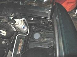
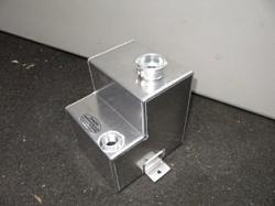
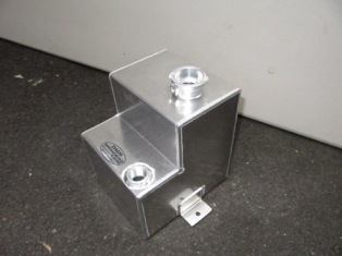
I am in the process of installing a custom built reserve tank (photo). I cut off the windshield washer fill tube and installed a new fill tube to create the room for my tank. You can see the new black flex tube extending up to the radiator shroud cover with a gromment on top. I hope to finish it next week.
__________________________
2001 VDP S/C
__________________________

2001 VDP S/C
#10
10-13-2010, 09:02 AM
Senior Member
The following 4 users liked this post by rocklandjag:
Jag Pilot (07-02-2013),
Jeff in Tucson (07-02-2013),
Panthro (11-20-2016),
Superchargedxkr (04-01-2023)
#12
10-13-2010, 06:11 PM

What are you trying to accomplish with the larger resevoir? Are you going to isolate the 2 cooling systems, add a second pump in line or possibly reroute the lines??? The tank is quite nice. I added a seperate resevoir to my supercharger circuit as well as isolating it from the cooling system & routing the lines to run in the opposite direction flowing from one cooler to the other then out. With the heat exchanger eliminated & a second pump on the discharge side then going to a 1 gallon resevoir mounted on the bumper, then feeding a Killer Chiller then back to the original pump I see coolant temps on the discharge side of the coolers at ambient temp, sometimes lower. When I first installed the Chiller the resevoir got so cold the entire bumper beam was cold to the touch. Please post photos of your project.
#13
07-02-2013, 05:35 AM

Veteran Member
this is what I did to my car to lower temperatures. The cost is low and the result is great!
in addition to the electric fan to the front radiator of the intercoolers I installed the thermostatic valve that opens before (Eurotoys LTD) of that series, I removed the lining of the hood, catalysts to 200 cells (a drain more freely promotes the flow of high-temperature gas outside), upgrade the EGR valve as recommended by Avos, I insulated the entire intake system with bandages to have the coolest air possible input to the motor.
in addition to the electric fan to the front radiator of the intercoolers I installed the thermostatic valve that opens before (Eurotoys LTD) of that series, I removed the lining of the hood, catalysts to 200 cells (a drain more freely promotes the flow of high-temperature gas outside), upgrade the EGR valve as recommended by Avos, I insulated the entire intake system with bandages to have the coolest air possible input to the motor.
#14
07-02-2013, 03:19 PM
Veteran Member
The following users liked this post:
User 070620 (07-03-2013)


Thread
Thread Starter
Forum
Replies
Last Post
Currently Active Users Viewing This Thread: 1 (0 members and 1 guests)